EP0558871A1 - Touche à structure feuilletée - Google Patents
Touche à structure feuilletée Download PDFInfo
- Publication number
- EP0558871A1 EP0558871A1 EP92810159A EP92810159A EP0558871A1 EP 0558871 A1 EP0558871 A1 EP 0558871A1 EP 92810159 A EP92810159 A EP 92810159A EP 92810159 A EP92810159 A EP 92810159A EP 0558871 A1 EP0558871 A1 EP 0558871A1
- Authority
- EP
- European Patent Office
- Prior art keywords
- light
- measuring device
- film
- key according
- distance
- Prior art date
- Legal status (The legal status is an assumption and is not a legal conclusion. Google has not performed a legal analysis and makes no representation as to the accuracy of the status listed.)
- Withdrawn
Links
Images


Classifications
-
- H—ELECTRICITY
- H03—ELECTRONIC CIRCUITRY
- H03K—PULSE TECHNIQUE
- H03K17/00—Electronic switching or gating, i.e. not by contact-making and –breaking
- H03K17/94—Electronic switching or gating, i.e. not by contact-making and –breaking characterised by the way in which the control signals are generated
- H03K17/965—Switches controlled by moving an element forming part of the switch
- H03K17/968—Switches controlled by moving an element forming part of the switch using opto-electronic devices
Definitions
- the invention relates to a key constructed in layers of films according to the preamble of claim 1. It further relates to a keyboard consisting of keys according to the invention.
- the invention has for its object to provide a key and a keyboard with several keys in a film structure or in a layer structure, which does not have the disadvantages mentioned or only to a reduced extent.
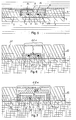
- the key is constructed in layers from a support film, a middle film and a cover film, the middle film having a recess for a measuring device. There is a cavity between the measuring device and the cover film, a pressure exerted on the cover film from the outside causing an elastic deformation in this area and thus a reduction in the distance between the cover film and the measurement device.
- the measuring device determines this distance using an optical measuring principle by means of a light-emitting element and a light-collecting element.
- the keys according to the invention can be integrated into a layered keyboard.
- the foil 3 forms the support for the other components of the key and can consist of known plastic materials, for example polyester or polycarbonate.
- the thickness of the film 3 is about 0.1 mm for a typical film keyboard, but can be freely selected in a wide range. Instead of the film 3 can a plate of any thickness made of plastic or of materials such as metal can also be provided.
- a cover film 1 Over the middle film 2 there is a cover film 1, the thickness of which is typically between 0.1 mm and 0.5 mm.
- the cover film 1 can also be made of a known plastic or metal.
- the measuring device 5 uses an optical measuring principle to determine the distance b from the cover film 1.
- a pressure exerted on the cover film 1 from the outside causes an elastic deformation of the cover film 1 in this area and thus a reduction in the distance b between the film 1 and of the measuring device 5.
- the cover film 1 in the area above the measuring device 5 must therefore be elastically deformable to a small extent, which is why the thickness of the middle film 2 must be selected at least so much greater than the overall height of the measuring device 5 that the cover film 1 when a key is pressed does not touch the measuring device 5 or does not touch it significantly.
- the reduction in the distance b when a key is pressed is usually in the range from one to several tenths of a millimeter.
- the cavity 14 enclosed by the cover film 1 of the middle film 2 and the support film 3 widens towards the cover film 1 in the example shown, which increases the elastically deformable area of the cover film 1 above the measuring device 5.
- the diameter of the elastically deformable area of the cover sheet 1 is approximately 10 mm, but can be selected in wide ranges depending on the intended use of the keyboard and the dimensioning of the measuring device 5.
- the measuring device 5 consists of a light-emitting element 6 and a light-collecting element 7, which are at a distance a.
- the Outlet opening 8a and the inlet opening 8b can be configured, for example, as a lens or as a flat surface.
- the elements 6 and 7 can be realized with electronic components, for example with an LED (Light Emitting Diode) and with a photosensitive semiconductor, the transparent body 13 usually forming part of these electronic components.
- the electrical supply and discharge lines for the measuring device 5 are implemented, for example, with a layer of conductor tracks 4, this layer coming, for example, between the middle film 2 and the support film 3.
- the support layer 3 and the conductor tracks 4 can also be prefabricated together, for example as a film printed with conductor tracks or as a circuit board such as a copper circuit board.
- FIG. 1b shows a membrane key with a measuring device 5, which consists of a passive, light-emitting element 6 and a passive light-collecting element 7.
- the light to be emitted is fed to the measuring device 5 via a light guide 15a and the received light is discharged again via a further light guide 15b.
- the light guide 15a is connected to a light source, not shown, and the light guide 15b is connected to a light-sensitive sensor, not shown.
- the light source and light sensor can be integrated in the button or can also be accommodated outside the button.
- FIG. 2a shows an embodiment of a measuring device 5, in which the light-emitting element with outlet opening 8a and the light-collecting element with inlet opening 8b are integrated in the same housing.
- the two elements can also be arranged as individual, separately designed components in the cavity 14, or can be embedded in the middle film 2.
- the light-emitting element 6 is accommodated in the glass body 13 and in this embodiment is preferably formed from a light-emitting diode (LED) together with the glass body 13.
- the light-collecting element 7 is a light-sensitive electronic sensor, the glass body 13 usually being a component of the sensor.
- the elements 6 and 7 are connected via the electrical contacts 17 e.g. contactable with conductor tracks 4.
- the elements 6 and 7 are spaced apart from one another by a, the distance between the center of the light-generating element 6 and the center of the light-collecting element 7, d.
- the installation depth of the two elements 6 and 7 within the measuring device 5 is denoted by c.
- 2c shows a further longitudinal section through a measuring device 5, in which the light is fed to the light-emitting element 6 via a light guide 15a, and the light is led away from the light-collecting element 7 via a light guide 15b.
- the elements 6 and 7 are usually embedded in a transparent body 13, which is used, among other things, for optical light guidance.
- FIG. 3 shows the relative output signal R of the measuring device 5 as a function of the distance b between the cover sheet 1 and the measuring device 5.
- three measuring ranges can be distinguished.
- area 18 there is a linear increase in the output signal R as a function of b.
- the light-emitting element 6 and the light-collecting element 7 are arranged, inter alia by the choice of the distance a, in such a way that the light emerging through the outlet opening 8a is achieved only through multiple reflections between the cover film 1 and the surface of the measuring device 5 arrives at the inlet opening 8b.
- the arrangement of the elements 6 and 7 and the distance b can also be selected such that the light reaches the inlet opening 8b of the light-collecting element 7 via the outlet opening 8a, preferably by a single reflection on the cover sheet 1. This results in a characteristic of the measuring device 5 according to the area 20.
- the area 18 is particularly suitable for detecting small changes in the distance b, whereas the area 20 is particularly suitable for the contactless detection of large key strokes.
- the area 19 is a transition area between the areas 18 and 20, and is poorly suited for a distance measurement.
- Fig. 4 shows a keyboard, which is constructed from individual, already described key elements.
- the layered design allows any number of key elements in the same layer structure to be integrated into a keyboard.
- Electrical connections for the measuring devices 5 can be established via conductor tracks 4.
- the conductor tracks 4 for supply connections, e.g. also be exposed.
- the conductor tracks can be routed away on a film extension which at the end e.g. is provided with a plug connection (not shown).
- a stroke limiting element 9 limits the key path of the cover film 1 by the U-shaped extensions of the limiting element 9 rest on the support film 3 or on the conductor tracks 4, and thus limit the key path b.
- FIG. 6 shows a button in which the middle film 2 and the cover film 1 are combined to form a cover plate 12, which can be chosen so thick that there is good mechanical protection of the button with the measuring device 5 arranged underneath.
- the material is e.g. Aluminum used.
- the cover plate 12 has an elastically deformable region 12a above the measuring device 5.
- the elastically deformable area 12a can e.g. 0.5 to 2 mm thick.
- the distance b is markedly greater than the distance a, which is why the measurement device 5 is used to measure in the area 20 according to the description of FIG. 3.
- FIG. 7 shows a further key with a cover plate 12 and an elastically deformable area 12a.
- a limiting element 10 which is partially connected to the region 12a, causes a small distance b, which, according to FIG. 3, allows the distance b to be measured in the region 18.
- a spacer element 16 effects a stroke limitation in that the limiter element 10 rests on the spacer element 16 when a large button is pressed.
Landscapes
- Push-Button Switches (AREA)
Priority Applications (1)
| Application Number | Priority Date | Filing Date | Title |
|---|---|---|---|
| EP92810159A EP0558871A1 (fr) | 1992-03-03 | 1992-03-03 | Touche à structure feuilletée |
Applications Claiming Priority (1)
| Application Number | Priority Date | Filing Date | Title |
|---|---|---|---|
| EP92810159A EP0558871A1 (fr) | 1992-03-03 | 1992-03-03 | Touche à structure feuilletée |
Publications (1)
| Publication Number | Publication Date |
|---|---|
| EP0558871A1 true EP0558871A1 (fr) | 1993-09-08 |
Family
ID=8211878
Family Applications (1)
| Application Number | Title | Priority Date | Filing Date |
|---|---|---|---|
| EP92810159A Withdrawn EP0558871A1 (fr) | 1992-03-03 | 1992-03-03 | Touche à structure feuilletée |
Country Status (1)
| Country | Link |
|---|---|
| EP (1) | EP0558871A1 (fr) |
Cited By (9)
| Publication number | Priority date | Publication date | Assignee | Title |
|---|---|---|---|---|
| FR2773257A1 (fr) * | 1997-12-31 | 1999-07-02 | Otis Elevator Co | Bouton poussoir opto-electronique, notamment pour les ascenseurs |
| EP1596499A1 (fr) * | 2004-05-12 | 2005-11-16 | Diehl AKO Stiftung & Co. KG | Commutateur à touche tactile |
| DE102004058478A1 (de) * | 2004-11-23 | 2006-05-24 | E.G.O. Elektro-Gerätebau GmbH | Bedienvorrichtung für ein Elektrogerät |
| ITRM20100304A1 (it) * | 2010-06-04 | 2011-12-05 | Amore Alberto D | Sensore per la misura di una forza esterna applicata a detto sensore. |
| WO2015086589A1 (fr) * | 2013-12-10 | 2015-06-18 | Behr-Hella Thermocontrol Gmbh | Dispositif de commande pour un appareil ou une installation électrique, en particulier pour un composant de véhicule à moteur |
| WO2016055139A1 (fr) * | 2014-10-09 | 2016-04-14 | Diehl Ako Stiftung & Co. Kg | Dispositif de commande, notamment pour appareil ménager électronique |
| WO2016177382A1 (fr) * | 2015-05-02 | 2016-11-10 | Diehl Ako Stiftung & Co. Kg | Dispositif de commande, notamment pour un appareil domestique électronique |
| WO2017162255A1 (fr) * | 2016-03-21 | 2017-09-28 | Diehl Ako Stiftung & Co. Kg | Dispositif de commande, en particulier pour un appareil ménager électronique |
| WO2017174097A1 (fr) * | 2016-04-07 | 2017-10-12 | Diehl Ako Stiftung & Co. Kg | Dispositif de commande, en particulier pour appareil domestique |
Citations (8)
| Publication number | Priority date | Publication date | Assignee | Title |
|---|---|---|---|---|
| GB1418318A (en) * | 1972-09-22 | 1975-12-17 | Nat Res Dev | Keyboard |
| DE2516171A1 (de) * | 1975-04-14 | 1976-10-21 | Rainer Dr Med Liedtke | Optisch-elektronischer tastschalter |
| US4405197A (en) * | 1980-11-25 | 1983-09-20 | The United States Of America As Represented By The Administrator Of The National Aeronautics And Space Administration | Optical fiber tactile sensor |
| WO1984003186A1 (fr) * | 1983-02-03 | 1984-08-16 | Arne Bergstroem | Element de circuit de radiation electromagnetique |
| WO1985004295A1 (fr) * | 1984-03-12 | 1985-09-26 | N.P. New Products Nordinvent Investment Ab | Montage pour claviers |
| WO1986001953A1 (fr) * | 1984-09-22 | 1986-03-27 | Michael John Nobbs | Commutateur |
| DE3822167A1 (de) * | 1988-06-30 | 1990-02-08 | Liess Hans Dieter Prof Dr Ing | Lichtschranke |
| EP0446642A1 (fr) * | 1990-03-13 | 1991-09-18 | Gaggenau-Werke Haus- und Lufttechnik GmbH | Dispositif pour mettre en circuit des installations électriques |
-
1992
- 1992-03-03 EP EP92810159A patent/EP0558871A1/fr not_active Withdrawn
Patent Citations (8)
| Publication number | Priority date | Publication date | Assignee | Title |
|---|---|---|---|---|
| GB1418318A (en) * | 1972-09-22 | 1975-12-17 | Nat Res Dev | Keyboard |
| DE2516171A1 (de) * | 1975-04-14 | 1976-10-21 | Rainer Dr Med Liedtke | Optisch-elektronischer tastschalter |
| US4405197A (en) * | 1980-11-25 | 1983-09-20 | The United States Of America As Represented By The Administrator Of The National Aeronautics And Space Administration | Optical fiber tactile sensor |
| WO1984003186A1 (fr) * | 1983-02-03 | 1984-08-16 | Arne Bergstroem | Element de circuit de radiation electromagnetique |
| WO1985004295A1 (fr) * | 1984-03-12 | 1985-09-26 | N.P. New Products Nordinvent Investment Ab | Montage pour claviers |
| WO1986001953A1 (fr) * | 1984-09-22 | 1986-03-27 | Michael John Nobbs | Commutateur |
| DE3822167A1 (de) * | 1988-06-30 | 1990-02-08 | Liess Hans Dieter Prof Dr Ing | Lichtschranke |
| EP0446642A1 (fr) * | 1990-03-13 | 1991-09-18 | Gaggenau-Werke Haus- und Lufttechnik GmbH | Dispositif pour mettre en circuit des installations électriques |
Non-Patent Citations (1)
| Title |
|---|
| IEEE INSTRUMENTATION AND MEASUREMENT TECHNOLOGY CONFERENCE Februar 1990, SAN JOSE, CA, US Seiten 141 - 143 PAUL P.L. REGTIEN 'Acurate Optical Proximity Detector' * |
Cited By (18)
| Publication number | Priority date | Publication date | Assignee | Title |
|---|---|---|---|---|
| FR2773257A1 (fr) * | 1997-12-31 | 1999-07-02 | Otis Elevator Co | Bouton poussoir opto-electronique, notamment pour les ascenseurs |
| EP1596499A1 (fr) * | 2004-05-12 | 2005-11-16 | Diehl AKO Stiftung & Co. KG | Commutateur à touche tactile |
| US7355164B2 (en) | 2004-05-12 | 2008-04-08 | Diehl Ako Stiftung & Co. Kg | Touch-sensitive momentary-contact switch and control device having the momentary-contact switch |
| DE102004058478A1 (de) * | 2004-11-23 | 2006-05-24 | E.G.O. Elektro-Gerätebau GmbH | Bedienvorrichtung für ein Elektrogerät |
| ITRM20100304A1 (it) * | 2010-06-04 | 2011-12-05 | Amore Alberto D | Sensore per la misura di una forza esterna applicata a detto sensore. |
| EP2392904A2 (fr) | 2010-06-04 | 2011-12-07 | Seconda Università degli Studi di Napoli | Capteur de mesure d' une force extérieure appliquée sur le dit capteur |
| EP2392904A3 (fr) * | 2010-06-04 | 2012-07-25 | Seconda Università degli Studi di Napoli | Capteur de mesure d' une force extérieure appliquée sur le dit capteur |
| WO2015086589A1 (fr) * | 2013-12-10 | 2015-06-18 | Behr-Hella Thermocontrol Gmbh | Dispositif de commande pour un appareil ou une installation électrique, en particulier pour un composant de véhicule à moteur |
| WO2016055139A1 (fr) * | 2014-10-09 | 2016-04-14 | Diehl Ako Stiftung & Co. Kg | Dispositif de commande, notamment pour appareil ménager électronique |
| CN106716841A (zh) * | 2014-10-09 | 2017-05-24 | 迪尔阿扣基金两合公司 | 尤其是用于电子的家用设备的操作装置 |
| CN106716841B (zh) * | 2014-10-09 | 2020-06-09 | 迪尔阿扣基金两合公司 | 用于电子的家用设备的操作装置 |
| WO2016177382A1 (fr) * | 2015-05-02 | 2016-11-10 | Diehl Ako Stiftung & Co. Kg | Dispositif de commande, notamment pour un appareil domestique électronique |
| WO2017162255A1 (fr) * | 2016-03-21 | 2017-09-28 | Diehl Ako Stiftung & Co. Kg | Dispositif de commande, en particulier pour un appareil ménager électronique |
| CN109075785A (zh) * | 2016-03-21 | 2018-12-21 | 迪尔阿扣基金两合公司 | 操作装置、特别是用于电子家用设备的操作装置 |
| CN109075785B (zh) * | 2016-03-21 | 2022-04-15 | 迪尔阿扣基金两合公司 | 操作装置、特别是用于电子家用设备的操作装置 |
| WO2017174097A1 (fr) * | 2016-04-07 | 2017-10-12 | Diehl Ako Stiftung & Co. Kg | Dispositif de commande, en particulier pour appareil domestique |
| CN108886362A (zh) * | 2016-04-07 | 2018-11-23 | 迪尔阿扣基金两合公司 | 操作装置、特别是用于电子家用设备的操作装置 |
| CN108886362B (zh) * | 2016-04-07 | 2022-09-27 | 迪尔阿扣基金两合公司 | 操作装置、特别是用于电子家用设备的操作装置 |
Similar Documents
| Publication | Publication Date | Title |
|---|---|---|
| DE19843155B4 (de) | Optische Verschiebungsmeßeinrichtung | |
| DE69712475T2 (de) | Bedienungstafel für eine Vorrichtung | |
| DE3803023C2 (fr) | ||
| DE60132460T2 (de) | Sensoreinheit, insbesondere für Fingerabdrucksensoren | |
| DE69528698T2 (de) | Näherungssensor mit mehrfacheingang und tastflächensystem | |
| DE2912049C2 (fr) | ||
| DE3512269A1 (de) | Kapazitive schalter | |
| DE102008029567A1 (de) | Beleuchteter kapazitiver Annäherungssensor | |
| DE2105071B2 (de) | Kapazitiver schalter | |
| EP0558871A1 (fr) | Touche à structure feuilletée | |
| DE3700856A1 (de) | Optoelektronische tastatur | |
| DE102009021436A1 (de) | Spektroskopiemodul | |
| DE102016123118B4 (de) | Eingabegerät mit einem Array von Kraftsensoren im Folienschichtaufbau mit verbesserter Hinterleuchtung | |
| EP1760886A2 (fr) | Dispositif de capteur | |
| DE102015015417A1 (de) | Bedienvorrichtung für einen Kraftwagen und Verfahren zur Erzeugung eines haptischen Signals | |
| DE69700243T2 (de) | Normalerweise geschlossener elektrischer Schalter | |
| DE102013003659B4 (de) | Beleuchteter kapazitiver Taster | |
| DE19744791C2 (de) | Kapazitive Tastatur | |
| WO2000008447A1 (fr) | Detecteur de gaz optoelectronique a base d'optodes | |
| DE2164202C3 (de) | Druckbetätigungsempfindliche Signalgabevorrichtung | |
| DE102022130496B3 (de) | Eingabegerät mit einem ein Array von Betätigungsflächen ausbildenden, flächigen Betätigungsteil und zugehörige Verwendung | |
| DE10146199C2 (de) | Druckmeßanordnung | |
| CH670345A5 (fr) | ||
| DE3604120C2 (fr) | ||
| DE8419690U1 (de) | Schaltvorrichtung mit optischer Anzeige |
Legal Events
| Date | Code | Title | Description |
|---|---|---|---|
| PUAI | Public reference made under article 153(3) epc to a published international application that has entered the european phase |
Free format text: ORIGINAL CODE: 0009012 |
|
| AK | Designated contracting states |
Kind code of ref document: A1 Designated state(s): CH DE FR LI SE |
|
| 17P | Request for examination filed |
Effective date: 19940214 |
|
| RAP1 | Party data changed (applicant data changed or rights of an application transferred) |
Owner name: ELMA ELECTRONIC AG |
|
| 17Q | First examination report despatched |
Effective date: 19960329 |
|
| 18D | Application deemed to be withdrawn |
Effective date: 19960809 |