EP0558932B1 - Buse multiple à fermeture à aiguille pour moules d'injection - Google Patents
Buse multiple à fermeture à aiguille pour moules d'injection Download PDFInfo
- Publication number
- EP0558932B1 EP0558932B1 EP93101486A EP93101486A EP0558932B1 EP 0558932 B1 EP0558932 B1 EP 0558932B1 EP 93101486 A EP93101486 A EP 93101486A EP 93101486 A EP93101486 A EP 93101486A EP 0558932 B1 EP0558932 B1 EP 0558932B1
- Authority
- EP
- European Patent Office
- Prior art keywords
- nozzle
- valve
- piston
- common
- needle
- Prior art date
- Legal status (The legal status is an assumption and is not a legal conclusion. Google has not performed a legal analysis and makes no representation as to the accuracy of the status listed.)
- Expired - Lifetime
Links
- 238000002347 injection Methods 0.000 title claims abstract description 11
- 239000007924 injection Substances 0.000 title claims abstract description 11
- 238000010438 heat treatment Methods 0.000 claims abstract description 12
- 238000006073 displacement reaction Methods 0.000 claims description 3
- 239000000463 material Substances 0.000 abstract description 4
- 238000000465 moulding Methods 0.000 abstract 1
- 238000007789 sealing Methods 0.000 description 4
- 238000005266 casting Methods 0.000 description 3
- 239000007921 spray Substances 0.000 description 3
- 238000006243 chemical reaction Methods 0.000 description 2
- 230000000694 effects Effects 0.000 description 2
- 238000001746 injection moulding Methods 0.000 description 2
- 238000000034 method Methods 0.000 description 2
- 230000001105 regulatory effect Effects 0.000 description 2
- 206010031009 Oral pain Diseases 0.000 description 1
- 238000010276 construction Methods 0.000 description 1
- 239000012778 molding material Substances 0.000 description 1
- 238000000926 separation method Methods 0.000 description 1
- 239000000243 solution Substances 0.000 description 1
- 230000001360 synchronised effect Effects 0.000 description 1
Images

Classifications
-
- B—PERFORMING OPERATIONS; TRANSPORTING
- B29—WORKING OF PLASTICS; WORKING OF SUBSTANCES IN A PLASTIC STATE IN GENERAL
- B29C—SHAPING OR JOINING OF PLASTICS; SHAPING OF MATERIAL IN A PLASTIC STATE, NOT OTHERWISE PROVIDED FOR; AFTER-TREATMENT OF THE SHAPED PRODUCTS, e.g. REPAIRING
- B29C45/00—Injection moulding, i.e. forcing the required volume of moulding material through a nozzle into a closed mould; Apparatus therefor
- B29C45/17—Component parts, details or accessories; Auxiliary operations
- B29C45/26—Moulds
- B29C45/27—Sprue channels ; Runner channels or runner nozzles
- B29C45/28—Closure devices therefor
- B29C45/2806—Closure devices therefor consisting of needle valve systems
- B29C45/281—Drive means therefor
- B29C2045/2813—Common drive means for several needle valves
-
- B—PERFORMING OPERATIONS; TRANSPORTING
- B29—WORKING OF PLASTICS; WORKING OF SUBSTANCES IN A PLASTIC STATE IN GENERAL
- B29C—SHAPING OR JOINING OF PLASTICS; SHAPING OF MATERIAL IN A PLASTIC STATE, NOT OTHERWISE PROVIDED FOR; AFTER-TREATMENT OF THE SHAPED PRODUCTS, e.g. REPAIRING
- B29C45/00—Injection moulding, i.e. forcing the required volume of moulding material through a nozzle into a closed mould; Apparatus therefor
- B29C45/17—Component parts, details or accessories; Auxiliary operations
- B29C45/26—Moulds
- B29C45/27—Sprue channels ; Runner channels or runner nozzles
- B29C45/28—Closure devices therefor
- B29C45/2806—Closure devices therefor consisting of needle valve systems
- B29C45/281—Drive means therefor
- B29C2045/2841—Needle valves driven by a plurality of coaxial pistons
Definitions
- the invention relates to a multiple valve gate nozzle for injection molds with at least two locking needles arranged in a common housing and having a common piston drive, each of which closes a nozzle orifice associated with it and in particular has a heater in the region of the nozzle orifice, with supply channels in the common housing Branches to the individual locking needles are arranged together.
- Such a multiple needle valve nozzle is known from DE-A-3733363.
- Multiple needle valve nozzles are known from practice and are used primarily to be able to inject relatively small parts in a narrow space in multiple injection molds, so that the multiple mold is used in the best possible way.
- the individual orifices of the multiple needle valve nozzles can namely because of their common drive and their arrangement in a common housing so closely next to each other that even small workpieces and their shape recesses in the multiple mold can be arranged accordingly close to each other.
- the solution to this multiple task in a multiple needle valve nozzle with a common housing is that the common housing below the feed channels and / or their branching is divided into spaced housing parts which have the individual locking needles and their nozzle orifices, that these housing parts are each between their walls have a space and are connected to the common housing, and that the distances or spaces between the individual housing parts provided below the housing area with the common feed channels and their branching are of such a size that a support for the multiple nozzle - in relation to the injection mold - fits between them.
- the housing parts which are separated from one another on the common housing, can therefore be located in the mouth region on account of their distance Carry out any heat movements without influencing and damaging each other.
- the spray pressure can be absorbed much better and more uniformly than the individual nozzle orifices and locking needles, which also makes it possible to avoid an unnecessarily large construction.
- the invention allows an advantageous embodiment with respect to the heating device at the nozzle mouth, which may consist in that a separate heating device is arranged on the individual nozzle mouths of the spaced apart housing parts and each heating device or nozzle mouth has its own temperature monitor or sensor for independent temperature control of each individual nozzle Has multiple needle valve nozzle. While in the previous multiple nozzles a common heating was to be provided for all the orifices, the arrangement of the invention allows the individual nozzle orifices to be precisely regulated to a required temperature. At the same time unwanted temperature influences of the individual nozzle orifices against each other are excluded.
- shut-off needles For a precise, synchronous and, above all, space-saving drive of the shut-off needles, it is expedient if the individual shut-off needles - the respective multiple-needle shut-off nozzle - engage parallel piston rods of the common piston drive and each have several pistons arranged coaxially to one another and in the direction of displacement are simultaneously provided acting on the locking needles.
- a piston is therefore provided for a multiple needle valve, which acts on several piston rods simultaneously, namely one for each valve valve, and at least one additional piston is present in the axial direction behind this piston in order to transmit a sufficiently large closing force to the valve needles .
- the drive pistons acting jointly on the locking needles are fastened to common, continuous piston rods and if the piston rods each penetrate a bottom of the cylinder chambers containing the individual pistons, which are arranged coaxially one behind the other in the feed direction, and are slidably guided in the passage openings of the bottoms .
- the piston rods can have at least as many sliding guides as coaxial drive pistons are connected to them and cylinder chambers for these drive pistons are arranged axially one behind the other. It is particularly expedient if the piston rods are each formed in one piece. You can the piston rods protrude beyond the piston furthest away from the locking needles with a protrusion and the protrusion can be guided in the cylinder cover or end - this most distant piston -, which results in an additional guide option.
- a third drive piston is provided and can be displaced in a separate, sealed cylinder chamber arranged axially behind the other cylinder chambers and with the piston rod is connected connected.
- a particularly expedient embodiment of the invention which at the same time allows a good fixation of the individual locking needles within the multiple nozzle and can thereby take advantage of the precise guidance of the piston rods, can consist in the fact that the end of the locking needles fits coaxially into a recess or perforation in the piston rods and is form-fitting therein but is releasably attached.
- the locking pins can thus be held not only in the axial but also in the transverse direction by the piston rods.
- the perforation of the piston rod extends beyond the piston furthest away from the needle and has an outwardly directed mouth, from which can be reached from the end of the locking needle, and if the locking needle can be pulled out and disassembled through the perforation of the piston rod, wherein the perforation can in particular be arranged centrally and concentrically in the piston rod.
- the through hole through the piston rod for receiving and disassembling the valve pin can preferably have a screw cap on its end facing away from the valve pin, in particular a screw serving as a screw, the inward end face of which simultaneously provides the axial stop for the end of the valve pin or can form an intermediate body between the closure and the needle end.
- the needle or the intermediate body coupled to it becomes accessible and can be pulled out in the axial direction with the needle.
- the front end of the locking needle or the intermediate body can have a perforation with an undercut or thread, into which a suitable tool or a tension screw can be inserted from the outside through the perforation of the piston rod, whereby the locking needle in particular with the intermediate body in the axial direction through the Piston rod can be pulled out.
- the invention thus makes it possible to provide a multiple needle shut-off nozzle in which a plurality of shut-off needles can be driven with sufficient force in a narrow space, even if only a relatively low pressure of the pressure medium is available, although mutual damage in the case of thermal expansions is eliminated in the sensitive mouth region and, if necessary, additional support is made possible.
- individual needle valve nozzles only have one valve needle, i.e. each nozzle mouth is independent of the other and its temperature can be regulated independently of the neighboring nozzle mouth, although all the mouths are closed belong to a common multiple valve gate nozzle.
- matching parts or parts with matching functions receive matching reference numbers even with a modified design.
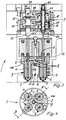
- a multiple-needle closure nozzle for injection molds can contain, according to FIGS. 1 and 2, two and according to FIGS. 3 and 4, four closure needles 4 arranged in a common housing 2 and having a common piston drive, designated as a whole by 3.
- Each valve pin 4 closes a nozzle orifice 5 assigned to it and can be withdrawn in the open position when the injection molding material is filled into the multiple mold.
- a heater 6 is arranged in each case in the area of the nozzle orifices 5.
- feed channels 7 with branches 8 from which the individual sealing needles 4 and the nozzle orifices 5 are each supplied with casting material.
- the common housing 2 viewed in the direction towards the nozzle orifices 5, below the feed channels 7 and their branches or branches 8 in spaced-apart housing parts which have the individual locking needles 4 and their nozzle orifices 5 9 is divided and that these housing parts 9 each have a space 11 between their outer walls 10, but are connected to the common housing 2.
- the housing 2 is given a "udder-like" design, the nozzle orifices 5 being spaced apart from one another by the intermediate space 11 such that they can carry out thermal movements independently of one another and do not damage themselves in the process.
- the distances between the individual housing parts 9 provided below the housing area with the common feed channels 7 and their branching 8 are of such a size that supports 11a fit the entire multiple nozzle 1.
- the spatial separation of the housing parts 9 belonging to the entire housing 2 in the region of the nozzle orifices 5 and the majority of the closure needles 4 thus permits a more stable support of the entire multiple nozzle not only on its outer circumference, but in the areas closer to its center.
- parallel piston rods 12 of the common piston drive act on the individual shut-off needles 4, wherein one can see in FIGS. 1 and 3 in each case several, namely two pistons 14 arranged coaxially to one another and in the direction of displacement, which each act simultaneously on the locking needles 4 of the multiple nozzle 1, that is to say can be accommodated in a very space-saving and compact manner.
- the piston rods 12 thus have at least as many slide guides formed through the passage openings 17 as coaxial drive pistons 14 are connected to them and cylinder chambers 16 for these drive pistons 14 are arranged axially one behind the other. This leads to a very stable holding and guiding of the piston rods 12, so that they do not tilt and the pistons 14 are not tilted even when there is a transverse load through the locking needles 4.
- the piston rods 12 are formed in one piece in the exemplary embodiments.
- a first and a further drive piston 14 are provided, but of course at least a third drive piston could be provided and be displaceable in a separate sealed cylinder chamber arranged axially behind the other cylinder chambers 16 and connected to the piston rods 12, if in a confined space and in view of a low pressure of the drive medium, a higher closing force would be required.
- FIGS. 1 and 3 it can also be seen that the end of the locking needles 4 fits coaxially into an opening or hole 22 in the piston rods 12 via an intermediate body 20 is positively but releasably attached. In this way, forces occurring across the longitudinal extension of the needles 4 can be absorbed well.
- the perforations 22 of the piston rod 12 each extend beyond the piston 14 furthest away from the needle 4 and have an outward opening from which the end of the locking needle 4 or the intermediate body 20 can be reached, so that the valve pin 4 can be pulled out and disassembled through this hole 22 in the piston rod 12.
- the perforation 22 is arranged centrally and concentrically in the piston rod 12 and practically filled by the intermediate body 20, while the cross section of the locking needle 4 is somewhat smaller.
- the perforation 22 has at its end facing away from the locking needle 4 a closure, which in the exemplary embodiment is designed as a screw 24, the inward end face of which simultaneously forms the axial stop for the end of the locking needle 4 or the intermediate body 20 between the closure and the needle end.
- the front, the closure 24 facing end of the intermediate body 20 has a threaded opening 25 for the screw 24, into which a suitable tool can be screwed in order to be able to pull the intermediate body 20 with the locking needle 4 in the axial direction through the piston rod 8.
- a new valve pin 4 can be re-installed in this way, so that replacement of individual valve needles 4 on the multiple nozzle 1 is possible in a simple manner and without mutual interference.
- the multiple valve gate nozzle 1 serves for the simultaneous loading of several individual molds in one injection mold and has two or more locking needles 4 arranged in a common housing 2 and having a common piston drive 3. Each locking needle 4 closes an associated nozzle orifice 5 on the multiple nozzle 1 and can be withdrawn therefrom for the injection of casting material.
- a separate heating device 6 can be arranged in the area of the respective nozzle mouth 5.
- feed channels 7 are provided with branches 8, which lead to the individual locking needles 4 and their mouths 5.
- the common housing 2 is divided below these common feed channels 7 and their branches 8 into spaced apart housing parts 9, which at least partially accommodate the individual locking needles 4 and have their nozzle orifices 5.
- the division is also spatially designed so that these housing parts 9 each have a space 11 between their walls 10 running around the needles 4 and are connected to the common housing 2, if necessary subsequently.
- supports 11 of the multiple nozzle can be accommodated below the common housing area between the housing parts 9.
Landscapes
- Engineering & Computer Science (AREA)
- Manufacturing & Machinery (AREA)
- Mechanical Engineering (AREA)
- Injection Moulding Of Plastics Or The Like (AREA)
- Moulds For Moulding Plastics Or The Like (AREA)
- Nozzles (AREA)
- Infusion, Injection, And Reservoir Apparatuses (AREA)
Claims (12)
- Buse multiple à fermeture à aiguilles (1) destinée à des moules de moulage par injection et comprenant au moins deux aiguilles de fermeture (4) qui sont disposées dans un carter commun (2), qui comportent un entraînement par pistons commun (3) et dont chacune ferme une embouchure de buse associée (5) et comporte en particulier un chauffage (6) dans la région de l'embouchure de buse (5), cependant que des canaux d'amenée (7) sont disposés en commun dans le carter commun (2) en étant pourvus d'embranchements (8) allant vers les diverses aiguilles de fermeture (4), caractérisée par le fait que le carter commun (2) est divisé, au-dessous des canaux d'amenée (7) et/ou de leur embranchement (8), en des parties de carter (9) qui comportent les diverses aiguilles de fermeture (4) et leurs embouchures de buse (5), par le fait que ces parties de carter (9) présentent chacune entre leurs parois (10) un espace intermédiaire (11), et qu'elles sont reliées au carter commun (2), et par le fait que les distances entre les diverses parties de carter (9) qui sont prévues au-dessous de la région du carter pourvue des canaux d'amenée communs (7) et de leur embranchement (8) présentent une valeur telle qu'un appui (11a) destiné à la buse multiple (1) s'ajuste entre elles.
- Buse multiple à fermeture à aiguilles selon la revendication 1, caractérisée par le fait qu'un dispositif de chauffage propre (6) est à chaque fois disposé sur les diverses embouchures de buse (5) des parties de carter (9) qui sont à distance les unes des autres, et que chaque dispositif de chauffage (6) ou chaque embouchure de buse (5) comporte un contrôleur ou un capteur de température qui lui est propre en vue d'une régulation indépendante de la température de chaque buse individuelle de la buse multiple à fermeture à aiguilles (1).
- Buse multiple à fermeture à aiguilles selon la revendication 1 ou 2, caractérisée par le fait que des tiges de piston parallèles (12) de l'entraînement par piston commun (3) viennent à chaque fois en prise avec les diverses aiguilles de fermeture (4), et que plusieurs pistons coaxiaux (14) qui sont disposés les uns derrière les autres dans la direction du coulissement sont à chaque fois prévus pour agir simultanément sur les aiguilles de fermeture (4).
- Buse multiple à fermeture à aiguilles selon l'une quelconque des revendications 1 à 3, caractérisée par le fait que les pistons d'entraînement (14) qui agissent en commun sur les aiguilles de fermeture (4) sont fixés sur des tiges de piston communes et continues (12), et par le fait que les tiges de piston (12) traversent à chaque fois un fond (15) des chambres de cylindres (16) qui contiennent les divers pistons (14) et qui sont disposées les unes derrière les autres d'une manière coaxiale dans la direction de l'avance, et qu'elles sont guidées en glissement dans les ouvertures de passage (17) des fonds (15).
- Buse multiple à fermeture à aiguilles selon l'une quelconque des revendications 1 à 4, caractérisée par le fait que les tiges de piston (12) présentent un nombre de guidages en glissement au moins égal au nombre des pistons d'entraînement coaxiaux (14) qui leur sont reliés et des chambres de cylindres (16) qui sont destinées à ces pistons d'entraînement (14) et qui sont disposées les unes derrière les autres dans le sens axial.
- Buse multiple à fermeture à aiguilles selon l'une quelconque des revendications 1 à 5, caractérisée par le fait que les tiges de piston (12) sont d'un seul tenant.
- Buse multiple à fermeture à aiguilles selon l'une quelconque des revendications 1 à 6, caractérisée par le fait que les tiges de piston (12) font saillie par un prolongement (18) au-delà des pistons (14) qui sont les plus éloignés des aiguilles de fermeture (4), et que le prolongement (18) est guidé dans le couvercle ou dans la fermeture (19) des cylindres.
- Buse multiple à fermeture à aiguilles selon l'une quelconque des revendications 1 à 7, caractérisée par le fait qu'en plus des pistons d'entraînement (14), il est prévu au moins un autre piston d'entraînement (14), par exemple un troisième piston d'entraînement, et qu'il est disposé en pouvant coulisser dans une chambre de cylindre qui lui est propre, qui est située derrière les autres chambres de cylindres (16) dans le sens axial et qui est fermée et rendue étanche, et en étant relié aux tiges de piston (12).
- Buse multiple à fermeture à aiguilles selon l'une quelconque des revendications 1 à 8, caractérisée par le fait que les extrémités des aiguilles de fermeture (4) s'ajustent d'une manière coaxiale dans un perçage (22) des tiges de piston (12), en particulier par l'intermédiaire de corps intermédiaires (20), et qu'elles sont fixées par conjugaison des formes, mais d'une manière amovible.
- Buse multiple à fermeture à aiguilles selon l'une quelconque des revendications 1 à 9, caractérisée par le fait que le perçage (22) des tiges de piston (12) s'étend jusqu'au-delà du piston (14) qui est le plus éloigné des aiguilles (4), et qu'il présente une embouchure qui est dirigée vers l'extérieur et depuis laquelle on peut atteindre l'extrémité de l'aiguille de fermeture (4), et par le fait que chaque aiguille de fermeture (4) peut être retirée et démontée à travers le perçage (22) de la tige de piston (12), le perçage (22) étant disposé en particulier dans la tige de piston (12) d'une manière centrée et coaxiale.
- Buse multiple à fermeture à aiguilles selon l'une quelconque des revendications 1 à 10, caractérisée par le fait que le perçage (22) qui traverse la tige de piston (12) et qui est destiné au logement et au démontage de l'aiguille de fermeture (4), et en particulier de son corps intermédiaire (20), présente une fermeture qui peut être posée sur son extrémité opposée à l'aiguille de fermeture (4) et qui est de préférence une fermeture à visser, et en particulier une vis (24) servant de fermeture, dont le côté frontal dirigé vers l'intérieur peut former en même temps la butée axiale qui est destinée à l'extrémité de l'aiguille de fermeture (4) ou au corps intermédiaire (20) entre la fermeture et l'extrémité de l'aiguille.
- Buse multiple à fermeture à aiguilles selon l'une quelconque des revendications 1 à 11, caractérisée par le fait que l'extrémité frontale de l'aiguille de fermeture (4) ou du corps intermédiaire (20) présente un perçage qui est pourvu d'une contre-dépouille ou d'un filetage dans lequel on peut introduire depuis l'extérieur, à travers le perçage (22) de la tige de piston (12), un outil adapté à cette fin ou une vis de traction au moyen de laquelle on peut retirer l'aiguille de fermeture (4), en particulier avec le corps intermédiaire (20), dans la direction axiale et à travers la tige de piston (12).
Applications Claiming Priority (3)
| Application Number | Priority Date | Filing Date | Title |
|---|---|---|---|
| DE4206318A DE4206318C2 (de) | 1992-02-29 | 1992-02-29 | Mehrfach-Nadelverschluß-Düse für Spritzgießformen |
| DE4206318 | 1992-02-29 | ||
| US08/113,400 US5368470A (en) | 1992-02-29 | 1993-08-27 | Multiple pin closure nozzle assembly for injection molds |
Publications (2)
| Publication Number | Publication Date |
|---|---|
| EP0558932A1 EP0558932A1 (fr) | 1993-09-08 |
| EP0558932B1 true EP0558932B1 (fr) | 1996-01-10 |
Family
ID=25912336
Family Applications (1)
| Application Number | Title | Priority Date | Filing Date |
|---|---|---|---|
| EP93101486A Expired - Lifetime EP0558932B1 (fr) | 1992-02-29 | 1993-01-30 | Buse multiple à fermeture à aiguille pour moules d'injection |
Country Status (6)
| Country | Link |
|---|---|
| US (1) | US5368470A (fr) |
| EP (1) | EP0558932B1 (fr) |
| JP (1) | JP3113087B2 (fr) |
| AT (1) | ATE132798T1 (fr) |
| DE (2) | DE4206318C2 (fr) |
| DK (1) | DK0558932T3 (fr) |
Cited By (1)
| Publication number | Priority date | Publication date | Assignee | Title |
|---|---|---|---|---|
| USRE41648E1 (en) | 2002-03-14 | 2010-09-07 | Mold-Masters (2007) Limited | Valve-gated injection molding system with side-mounted actuator |
Families Citing this family (20)
| Publication number | Priority date | Publication date | Assignee | Title |
|---|---|---|---|---|
| US5650178A (en) * | 1994-11-23 | 1997-07-22 | Bemis Manufacturing Company | Co-injection manifold for injection molding |
| WO2000051803A1 (fr) * | 1999-02-26 | 2000-09-08 | Mold-Masters Limited | Appareil de moulage par injection a empreintes multiples separant la matiere fondue a proximite de la partie avant de la buse |
| CA2264224A1 (fr) * | 1999-02-26 | 2000-08-26 | Denis Babin | Moule a injection a empreintes multiples separant la fonte a l'avant des busettes |
| WO2001064419A1 (fr) * | 2000-02-29 | 2001-09-07 | Bemis Manufacturing Company | Appareil a co-injection pour moulage par injection |
| US6386508B1 (en) | 2000-06-05 | 2002-05-14 | D-M-E Company | Actuator having dual piston surfaces |
| US6755641B1 (en) * | 2000-09-01 | 2004-06-29 | Mold-Masters Limited | Stack injection molding apparatus with separately actuated arrays of valve gates |
| CA2364050A1 (fr) * | 2000-11-30 | 2002-05-30 | Bemis Manufacturing Company | Methodes de co-injection utilisant des agents gonflants endothermiques et produits obtenus grace a ces methodes |
| DE10231093C1 (de) * | 2002-07-10 | 2003-10-30 | Otto Maenner Heiskanalsysteme | Spritzgießdüse für Kunststoff mit wenigstens zwei Austrittsöffnungen |
| CA2437076C (fr) * | 2002-08-14 | 2010-10-12 | Mold-Masters Limited | Dispositif de reglage de tige de robinet |
| US6719263B1 (en) | 2002-09-20 | 2004-04-13 | D-M-E Company | Multi-piston valve actuator |
| US7192270B2 (en) * | 2002-11-05 | 2007-03-20 | Mold-Masters Limited | Tight pitch nozzle with individual valve gate control |
| DE202004019328U1 (de) * | 2004-10-20 | 2005-02-24 | Mold-Masters Ltd., Georgetown | Spritzgießvorrichtung mit Ventilnadelverdrehsicherung |
| DE102005049605A1 (de) * | 2004-10-19 | 2006-04-20 | Mold-Masters Ltd., Georgetown | Verteilereinsatz für eine Spritzgießvorrichtung |
| KR100810667B1 (ko) * | 2004-12-15 | 2008-03-07 | 허남욱 | 멀티 핫런너 밸브장치 |
| US7390184B2 (en) * | 2005-11-09 | 2008-06-24 | Centoco Plastics Limited | Dual injection manifold |
| EP2008790A2 (fr) | 2007-06-27 | 2008-12-31 | AWM Mold Tech AG | Agencement de douille d'obturateur à aiguille |
| US7618253B2 (en) | 2007-10-19 | 2009-11-17 | Mold-Masters (2007) Limited | Multiple-gate injection molding apparatus |
| PT3326776T (pt) * | 2014-03-10 | 2020-01-21 | Inglass Spa | Placa de fixação de um molde de um aparelho de moldagem de material plástico por injeção |
| CN108908860B (zh) * | 2018-06-30 | 2024-07-12 | 深圳市麦士德福科技股份有限公司 | 一种用于注塑热固性塑料的模具 |
| CN110720482B (zh) * | 2019-10-25 | 2021-07-27 | 马鞍山市春晖食品有限责任公司 | 一种食品注浆机 |
Family Cites Families (13)
| Publication number | Priority date | Publication date | Assignee | Title |
|---|---|---|---|---|
| DE2004212A1 (de) * | 1970-01-30 | 1971-08-05 | Louis Felder | Druckgasbeaufschlagte Kolben-Zylinder-Anordnung |
| US3847528A (en) * | 1972-11-29 | 1974-11-12 | Improved Machinery Inc | Clamping force applying means for molding machines |
| US4279582A (en) | 1979-04-02 | 1981-07-21 | Incoe Corporation | Method and apparatus for individual control of injection mold shut-off bushings |
| EP0021273B1 (fr) * | 1979-06-12 | 1984-09-12 | Hendrikus Jacobus Elisabeth Schouenberg | Mécanisme d'injection pour mouler des matières plastiques |
| DE3249486C2 (de) * | 1982-12-09 | 1992-03-05 | Männer, Otto, 7836 Bahlingen | Nadelverschluß-Düse mit Kolbenantrieb für Spritzgießformen |
| DE3336258C2 (de) * | 1983-10-05 | 1986-04-17 | HASCO-Normalien Hasenclever & Co, 5880 Lüdenscheid | Spritzgieß- oder Preßwerkzeug zur Verarbeitung von Kunststoffmassen |
| DE3403603C2 (de) * | 1984-02-02 | 1985-12-05 | Maschinenfabrik Köppern GmbH & Co KG, 4320 Hattingen | Zwangsgesteuerter Nadelverschluß für Spritzdüsen in Spritzgießformen |
| DE3590090T (de) * | 1984-02-28 | 1986-04-24 | JU-OH Trading Co., Ltd., Hiratsuka, Kanagawa | Heißkanal-Spritzgießanlage |
| JPS6387304U (fr) * | 1986-11-28 | 1988-06-07 | ||
| DE3733363A1 (de) * | 1987-10-02 | 1989-04-13 | Horst Prinz | Heisskanalnadelverschlussduese zur verarbeitung thermoplastischer massen |
| US5066216A (en) * | 1989-09-22 | 1991-11-19 | Binney & Smith Inc. | Apparatus for injection of viscous material |
| US5078589A (en) | 1990-06-15 | 1992-01-07 | Osuna Diaz J M | Multicavity injection molding apparatus having precision adjustment and shut off of injection flow to individual mold cavities |
| DE4034934C2 (de) * | 1990-11-02 | 1994-03-17 | Prima Heiskanaltechnik Gmbh | Tandemdüse zum Verarbeiten von thermoplastischen Massen |
-
1992
- 1992-02-29 DE DE4206318A patent/DE4206318C2/de not_active Expired - Lifetime
- 1992-09-08 JP JP04239302A patent/JP3113087B2/ja not_active Expired - Lifetime
-
1993
- 1993-01-30 EP EP93101486A patent/EP0558932B1/fr not_active Expired - Lifetime
- 1993-01-30 AT AT93101486T patent/ATE132798T1/de active
- 1993-01-30 DK DK93101486.4T patent/DK0558932T3/da active
- 1993-01-30 DE DE59301369T patent/DE59301369D1/de not_active Expired - Lifetime
- 1993-08-27 US US08/113,400 patent/US5368470A/en not_active Expired - Lifetime
Cited By (1)
| Publication number | Priority date | Publication date | Assignee | Title |
|---|---|---|---|---|
| USRE41648E1 (en) | 2002-03-14 | 2010-09-07 | Mold-Masters (2007) Limited | Valve-gated injection molding system with side-mounted actuator |
Also Published As
| Publication number | Publication date |
|---|---|
| US5368470A (en) | 1994-11-29 |
| EP0558932A1 (fr) | 1993-09-08 |
| JPH05278075A (ja) | 1993-10-26 |
| DE4206318A1 (de) | 1993-09-02 |
| ATE132798T1 (de) | 1996-01-15 |
| DK0558932T3 (da) | 1996-06-03 |
| JP3113087B2 (ja) | 2000-11-27 |
| DE4206318C2 (de) | 1994-06-16 |
| DE59301369D1 (de) | 1996-02-22 |
Similar Documents
| Publication | Publication Date | Title |
|---|---|---|
| EP0558932B1 (fr) | Buse multiple à fermeture à aiguille pour moules d'injection | |
| DE4206319C2 (de) | Nadelverschlußdüse mit Kolbenantrieb | |
| DE3049282C2 (fr) | ||
| DE2613040A1 (de) | Spritzgiessmaschine fuer kunststoff und verschlusshuelse fuer diese | |
| DE3245571A1 (de) | Nadelverschluss-duese fuer spritzgiessformen | |
| EP2008790A2 (fr) | Agencement de douille d'obturateur à aiguille | |
| DE69414285T2 (de) | Giessvorrichtungen | |
| DE3403603C2 (de) | Zwangsgesteuerter Nadelverschluß für Spritzdüsen in Spritzgießformen | |
| EP3104981B1 (fr) | Ensemble de vannes de dépôt de milieux fluides sur des surfaces | |
| DE10231093C1 (de) | Spritzgießdüse für Kunststoff mit wenigstens zwei Austrittsöffnungen | |
| DE3037111A1 (de) | Vorrichtung zur behandlung von faeden mit einer behandlungsduese, eine solche duese sowie eine duesenanordnung mit einer mehrzahl solcher duesen | |
| DE69121668T2 (de) | Verfahren und Vorrichtung zum Weben eines mehrachsigen dreidimensionalen Gewebes mit hilfe von Stäben | |
| DE68913467T2 (de) | Spinndüse zur Herstellung von Membranen aus einem organischen Material mit mindestens einem Längskanal. | |
| DE4219924A1 (de) | Spritzgießmaschine mit Etagenwerkzeug | |
| DE4229254A1 (de) | Spritzaggregat für eine Zweikomponentenspritzgießmaschine | |
| AT526892B1 (de) | Holmlose Schließeinheit | |
| DE4323131A1 (de) | Vorrichtung zum Verwirbeln von Filamenten mit einer Vielzahl von Verwirbelungsdüsen | |
| DE2544894A1 (de) | Formschliesseinrichtung fuer giessmaschinen | |
| DE4221423C2 (de) | Verfahren und Vorrichtung zum Herstellen von Gegenständen aus thermoplastischem Kunststoff durch Spritzgießen | |
| DE3213153A1 (de) | Mischkopf | |
| WO1985005275A1 (fr) | Seringue d'injection | |
| DE112014005406T5 (de) | Heißkanalspritzgießvorrichtung und Verfahren zum seitlichen Anspritzen mit unabhängigen Ventilnadeln | |
| DE1479748C2 (de) | Maschine zum Herstellen von Formteilen aus expandierbaren Kunststoffen | |
| EP1587659A1 (fr) | Dispositif pour distribuer de la matiere plastique en fusion dans un moule de coulage par injection avec plusieurs etages | |
| DE19820934C2 (de) | Formschließeinheit für eine Spritzgießmaschine |
Legal Events
| Date | Code | Title | Description |
|---|---|---|---|
| PUAI | Public reference made under article 153(3) epc to a published international application that has entered the european phase |
Free format text: ORIGINAL CODE: 0009012 |
|
| 17P | Request for examination filed |
Effective date: 19930715 |
|
| AK | Designated contracting states |
Kind code of ref document: A1 Designated state(s): AT BE CH DE DK FR GB IT LI LU NL PT |
|
| 17Q | First examination report despatched |
Effective date: 19941216 |
|
| GRAA | (expected) grant |
Free format text: ORIGINAL CODE: 0009210 |
|
| AK | Designated contracting states |
Kind code of ref document: B1 Designated state(s): AT BE CH DE DK FR GB IT LI LU NL PT |
|
| REF | Corresponds to: |
Ref document number: 132798 Country of ref document: AT Date of ref document: 19960115 Kind code of ref document: T |
|
| ET | Fr: translation filed | ||
| REF | Corresponds to: |
Ref document number: 59301369 Country of ref document: DE Date of ref document: 19960222 |
|
| REG | Reference to a national code |
Ref country code: CH Ref legal event code: NV Representative=s name: HANS RUDOLF GACHNANG PATENTANWALT |
|
| ITF | It: translation for a ep patent filed | ||
| SC4A | Pt: translation is available |
Free format text: 960115 AVAILABILITY OF NATIONAL TRANSLATION |
|
| GBT | Gb: translation of ep patent filed (gb section 77(6)(a)/1977) |
Effective date: 19960417 |
|
| REG | Reference to a national code |
Ref country code: DK Ref legal event code: T3 |
|
| PLBE | No opposition filed within time limit |
Free format text: ORIGINAL CODE: 0009261 |
|
| STAA | Information on the status of an ep patent application or granted ep patent |
Free format text: STATUS: NO OPPOSITION FILED WITHIN TIME LIMIT |
|
| 26N | No opposition filed | ||
| REG | Reference to a national code |
Ref country code: GB Ref legal event code: IF02 |
|
| PGFP | Annual fee paid to national office [announced via postgrant information from national office to epo] |
Ref country code: LU Payment date: 20110124 Year of fee payment: 19 |
|
| PGFP | Annual fee paid to national office [announced via postgrant information from national office to epo] |
Ref country code: CH Payment date: 20120124 Year of fee payment: 20 Ref country code: FR Payment date: 20120201 Year of fee payment: 20 |
|
| PGFP | Annual fee paid to national office [announced via postgrant information from national office to epo] |
Ref country code: DE Payment date: 20120131 Year of fee payment: 20 Ref country code: PT Payment date: 20120118 Year of fee payment: 20 |
|
| PGFP | Annual fee paid to national office [announced via postgrant information from national office to epo] |
Ref country code: GB Payment date: 20120124 Year of fee payment: 20 Ref country code: IT Payment date: 20120126 Year of fee payment: 20 Ref country code: DK Payment date: 20120125 Year of fee payment: 20 Ref country code: BE Payment date: 20120123 Year of fee payment: 20 |
|
| PGFP | Annual fee paid to national office [announced via postgrant information from national office to epo] |
Ref country code: NL Payment date: 20120127 Year of fee payment: 20 |
|
| REG | Reference to a national code |
Ref country code: DE Ref legal event code: R082 Ref document number: 59301369 Country of ref document: DE Representative=s name: PATENTANWAELTE DIMMERLING & HUWER, DE |
|
| BE20 | Be: patent expired |
Owner name: *MANNER OTTO Effective date: 20130130 |
|
| REG | Reference to a national code |
Ref country code: DE Ref legal event code: R071 Ref document number: 59301369 Country of ref document: DE |
|
| REG | Reference to a national code |
Ref country code: DK Ref legal event code: EUP |
|
| REG | Reference to a national code |
Ref country code: NL Ref legal event code: V4 Effective date: 20130130 |
|
| REG | Reference to a national code |
Ref country code: PT Ref legal event code: MM4A Free format text: MAXIMUM VALIDITY LIMIT REACHED Effective date: 20130130 |
|
| REG | Reference to a national code |
Ref country code: GB Ref legal event code: PE20 Expiry date: 20130129 |
|
| REG | Reference to a national code |
Ref country code: AT Ref legal event code: MK07 Ref document number: 132798 Country of ref document: AT Kind code of ref document: T Effective date: 20130130 |
|
| PGFP | Annual fee paid to national office [announced via postgrant information from national office to epo] |
Ref country code: AT Payment date: 20120123 Year of fee payment: 20 |
|
| PG25 | Lapsed in a contracting state [announced via postgrant information from national office to epo] |
Ref country code: GB Free format text: LAPSE BECAUSE OF EXPIRATION OF PROTECTION Effective date: 20130129 Ref country code: DE Free format text: LAPSE BECAUSE OF EXPIRATION OF PROTECTION Effective date: 20130131 |
|
| PG25 | Lapsed in a contracting state [announced via postgrant information from national office to epo] |
Ref country code: PT Free format text: LAPSE BECAUSE OF EXPIRATION OF PROTECTION Effective date: 20130207 |