EP0558982A2 - Dispositif pour l'usinage des profilés creux le long plusieurs faces - Google Patents
Dispositif pour l'usinage des profilés creux le long plusieurs faces Download PDFInfo
- Publication number
- EP0558982A2 EP0558982A2 EP93102311A EP93102311A EP0558982A2 EP 0558982 A2 EP0558982 A2 EP 0558982A2 EP 93102311 A EP93102311 A EP 93102311A EP 93102311 A EP93102311 A EP 93102311A EP 0558982 A2 EP0558982 A2 EP 0558982A2
- Authority
- EP
- European Patent Office
- Prior art keywords
- machine frame
- clamping device
- hollow profile
- swivel
- axis
- Prior art date
- Legal status (The legal status is an assumption and is not a legal conclusion. Google has not performed a legal analysis and makes no representation as to the accuracy of the status listed.)
- Granted
Links
- 238000003754 machining Methods 0.000 claims abstract description 20
- 238000003801 milling Methods 0.000 abstract description 16
- 238000005520 cutting process Methods 0.000 abstract description 11
- 229910000831 Steel Inorganic materials 0.000 description 3
- XAGFODPZIPBFFR-UHFFFAOYSA-N aluminium Chemical compound [Al] XAGFODPZIPBFFR-UHFFFAOYSA-N 0.000 description 3
- 229910052782 aluminium Inorganic materials 0.000 description 3
- 238000010276 construction Methods 0.000 description 3
- 239000010959 steel Substances 0.000 description 3
- 240000007124 Brassica oleracea Species 0.000 description 2
- 235000003899 Brassica oleracea var acephala Nutrition 0.000 description 2
- 235000011301 Brassica oleracea var capitata Nutrition 0.000 description 2
- 235000001169 Brassica oleracea var oleracea Nutrition 0.000 description 2
- 238000004519 manufacturing process Methods 0.000 description 2
- 238000000034 method Methods 0.000 description 2
- 229910000838 Al alloy Inorganic materials 0.000 description 1
- 230000001419 dependent effect Effects 0.000 description 1
- 238000005553 drilling Methods 0.000 description 1
- 230000002349 favourable effect Effects 0.000 description 1
- 239000003517 fume Substances 0.000 description 1
- 239000011344 liquid material Substances 0.000 description 1
Images


Classifications
-
- B—PERFORMING OPERATIONS; TRANSPORTING
- B23—MACHINE TOOLS; METAL-WORKING NOT OTHERWISE PROVIDED FOR
- B23Q—DETAILS, COMPONENTS, OR ACCESSORIES FOR MACHINE TOOLS, e.g. ARRANGEMENTS FOR COPYING OR CONTROLLING; MACHINE TOOLS IN GENERAL CHARACTERISED BY THE CONSTRUCTION OF PARTICULAR DETAILS OR COMPONENTS; COMBINATIONS OR ASSOCIATIONS OF METAL-WORKING MACHINES, NOT DIRECTED TO A PARTICULAR RESULT
- B23Q1/00—Members which are comprised in the general build-up of a form of machine, particularly relatively large fixed members
- B23Q1/25—Movable or adjustable work or tool supports
- B23Q1/44—Movable or adjustable work or tool supports using particular mechanisms
- B23Q1/50—Movable or adjustable work or tool supports using particular mechanisms with rotating pairs only, the rotating pairs being the first two elements of the mechanism
- B23Q1/52—Movable or adjustable work or tool supports using particular mechanisms with rotating pairs only, the rotating pairs being the first two elements of the mechanism a single rotating pair
- B23Q1/527—Movable or adjustable work or tool supports using particular mechanisms with rotating pairs only, the rotating pairs being the first two elements of the mechanism a single rotating pair with a ring or tube in which a workpiece is fixed coaxially to the degree of freedom
-
- B—PERFORMING OPERATIONS; TRANSPORTING
- B23—MACHINE TOOLS; METAL-WORKING NOT OTHERWISE PROVIDED FOR
- B23K—SOLDERING OR UNSOLDERING; WELDING; CLADDING OR PLATING BY SOLDERING OR WELDING; CUTTING BY APPLYING HEAT LOCALLY, e.g. FLAME CUTTING; WORKING BY LASER BEAM
- B23K37/00—Auxiliary devices or processes, not specially adapted for a procedure covered by only one of the other main groups of this subclass
- B23K37/04—Auxiliary devices or processes, not specially adapted for a procedure covered by only one of the other main groups of this subclass for holding or positioning work
- B23K37/0426—Fixtures for other work
- B23K37/0452—Orientable fixtures
-
- B—PERFORMING OPERATIONS; TRANSPORTING
- B23—MACHINE TOOLS; METAL-WORKING NOT OTHERWISE PROVIDED FOR
- B23Q—DETAILS, COMPONENTS, OR ACCESSORIES FOR MACHINE TOOLS, e.g. ARRANGEMENTS FOR COPYING OR CONTROLLING; MACHINE TOOLS IN GENERAL CHARACTERISED BY THE CONSTRUCTION OF PARTICULAR DETAILS OR COMPONENTS; COMBINATIONS OR ASSOCIATIONS OF METAL-WORKING MACHINES, NOT DIRECTED TO A PARTICULAR RESULT
- B23Q1/00—Members which are comprised in the general build-up of a form of machine, particularly relatively large fixed members
- B23Q1/25—Movable or adjustable work or tool supports
- B23Q1/44—Movable or adjustable work or tool supports using particular mechanisms
- B23Q1/48—Movable or adjustable work or tool supports using particular mechanisms with sliding pairs and rotating pairs
- B23Q1/4804—Movable or adjustable work or tool supports using particular mechanisms with sliding pairs and rotating pairs a single rotating pair followed perpendicularly by a single sliding pair
- B23Q1/4809—Movable or adjustable work or tool supports using particular mechanisms with sliding pairs and rotating pairs a single rotating pair followed perpendicularly by a single sliding pair followed perpendicularly by a single rotating pair
-
- B—PERFORMING OPERATIONS; TRANSPORTING
- B27—WORKING OR PRESERVING WOOD OR SIMILAR MATERIAL; NAILING OR STAPLING MACHINES IN GENERAL
- B27F—DOVETAILED WORK; TENONS; SLOTTING MACHINES FOR WOOD OR SIMILAR MATERIAL; NAILING OR STAPLING MACHINES
- B27F5/00—Slotted or mortised work
- B27F5/02—Slotting or mortising machines tools therefor
- B27F5/12—Slotting or mortising machines tools therefor for making holes designed for taking up fittings, e.g. in frames of doors, windows, furniture
Definitions
- the invention relates to a device for multi-sided machining of hollow profiles by means of a machining unit which can be moved in a multi-axis program-controlled manner on a machine frame, with a clamping device mounted in the machine frame for the hollow profile to be machined.
- Hollow profiles made of aluminum, aluminum alloys and / or plastic are usually machined by milling.
- milling hollow steel profiles there is a relatively high level of milling wear; Therefore, the processing of steel cabbage profiles is increasingly done by plasma cutting. Since harmful fumes are generated during plasma cutting and must be extracted, and since there is a considerable amount of sparks, a closed design of the machine would also be desirable for plasma cutting.
- the workpiece has to be reclamped for machining on several sides, because plasma cutting is only possible with the plasma torch arranged vertically; otherwise the recess would be made inaccurately or the liquid material flowing back to the plasma torch would interfere with the cutting process.
- the object of the invention is therefore to design a device of the type mentioned in such a way that reclamping of the hollow profile is not necessary in the case of multi-sided machining.
- clamping device in the machine frame is pivotably mounted about at least 180 ° about a pivot axis running parallel to the longitudinal axis of the hollow profile and is provided with a pivot drive.
- the processing unit has either a milling head or a plasma cutting head and is preferably arranged vertically.
- the machine frame has a largely closed box enclosing at least the clamping device with a hinged hood.
- the hood only has to be opened to insert the hollow profile to be machined and to remove it after complete, all-round machining.
- the clamping device has two spaced-apart, rigidly interconnected end disks, that each end disk has a recess extending at least to the middle of the disk for receiving the hollow profile, that each End disk on its circumference forms a circular arc guide, which extends over an arc angle of at least approximately 270 ° and runs concentrically to the swivel axis, with which the end disk is mounted in the machine frame, and that the machine frame is open on one side and offers radial access to the pivotable clamping device.
- the structural design of the clamping device from two rigidly connected end plates enables a particularly simple and lightweight construction, which nevertheless ensures stable and secure clamping of the hollow profile. It is particularly advantageous that the hollow profile to be machined is largely freely accessible to the machining unit in the area between the two end disks, so that all required side surfaces can be machined in all pivot positions.
- a construction of the swivel drive which is particularly favorable in terms of construction costs and the method of operation consists in the fact that the swivel drive has two pressure-cylinder actuated swivel cylinders which are mounted at a distance from one another on the machine frame and act at a distance from the swivel axis on the clamping device.
- the clamping device is brought into and held in the respectively desired pivot position by suitable control of these two pivot cylinders.
- This version is preferably chosen when only three sides of an essentially rectangular hollow profile have to be machined, ie when a swivel of at most 180 ° is required.
- a swivel drive is preferably used, which has a sprocket mounted on the clamping device concentrically to the swivel axis and which engages with a drive pinion mounted on the machine frame.
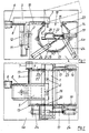
- the device shown in Figures 1 to 4 is used to process a hollow profile 1, for example for the production of door or window frames. Openings 2 are to be milled in three side surfaces of the hollow profile 1, which are made of aluminum, for example, which are at right angles to one another. For this purpose, a milling head with a vertical milling axis is provided as the machining unit 3.
- the device has a machine frame 4, on the top of which a carriage 5 can be moved in three axes, which carries the processing unit 3.
- the length and width adjustment of the carriage 5 is carried out by a (not shown) two-axis CNC control which controls two motors 6 and 7.
- the motors 6 and 7 each drive a threaded spindle 8 or 9, with which the carriage 5 is moved in guides 10 or 11 on the machine frame 4.
- the height adjustment of the slide 5 in the exemplary embodiment shown is carried out by a vertical air cylinder 12.
- the machine frame 4 has two mutually rigidly connected cheeks 13, in each of which a central recess 14 is provided, which is open toward the top of the machine frame 4.
- the recesses 14 serve to pivotally accommodate a clamping device 15 in which the cabbage profile 1 to be machined can be clamped.
- the clamping device 15 has two end disks 17 which are arranged at a distance from one another and are rigidly connected to one another by a web 16. Each face plate 17 lies approximately in the plane of the associated cheek 13 of the machine frame 4 in the respective recess 14 of this cheek 4.
- Each face plate 17 has a recess 18, which extends approximately to the center of the plate, for receiving the hollow profile 1.
- the hollow profile 1 is provided by two pressure-actuated, preferably air-actuated clamping cylinders 19, each of which is attached to the Face plate 17 is arranged, clamped against an opposite contact surface 20 of the face plate 17.
- Each of the two end disks 17 forms on its circumference an arcuate guide 21 which extends over an arc angle of slightly more than 270 ° and runs concentrically to a horizontal pivot axis 22 of the clamping device.
- This pivot axis 22 extends parallel to the longitudinal axis of the hollow profile 1 to be machined.
- the two end disks 17 are supported with their circular arc guide 21 in a plurality of bearing rollers 23 which are distributed on the circumference of the end disk 17 and are attached to the machine frame 4.
- the swivel drive for the clamping device 15 has two pressure-actuated swivel cylinders 24, which are mounted at a distance from one another on the outside of the one cheek 4.
- the piston rods of the two swivel cylinders 24 act on the one end plate 17 of the clamping device 15 at a distance from the swivel axis 22.
- FIGS. 1, 3 and 4. 1 shows the starting position, in which the recess 18 of the end disks 17 is accessible from above for receiving the hollow profile 1. Since the recess 14 of the machine frame 4 is also opened upwards, radial access for inserting the hollow profile 1 is made in this way created. This eliminates the need to insert the hollow profile 1 in the longitudinal direction, whereby a surface-treated one Hollow section 1 damage could be caused. In this pivot position shown in Fig. 1, the upper side wall of the hollow profile 1 can be processed.
- the machine frame 4 has a largely closed box 4a which encloses the entire machine, but at least the clamping device 15, with a hood 4b which can be opened.
- the hood 4b is closed.
- the processing unit 3 is moved downward by means of the air cylinder 12; the milling cutter dips into the hollow profile 1 and carries out the machining, the CNC-controlled motors 6 and 7 moving the machining unit 3 in such a way that the programmed milling pattern is traversed.
- the processing unit 3 is then raised by means of the air cylinder 12 and the clamping device 15 is pivoted by 90 ° into the pivot position shown in FIG. 3.
- the second side surface of the hollow profile 1 is then machined.
- the third side wall of the hollow profile 1 is machined in the manner already described.
- the clamping device 15 is then pivoted back into the starting position shown in FIG. 1. After loosening the clamping cylinder 19 and opening the hood 4b, the machined hollow profile 1 can be removed.
- FIGS. 5 and 6 differs from the previously described exemplary embodiment essentially only in that the swivel drive for the clamping device 15 has a ring gear 25 which is arranged concentrically with the swivel axis 22 on one of the two end disks 17 and which has a on the machine frame 4 mounted drive pinions 26 is engaged, which is driven by a swivel motor 27. Since the ring gear 25 extends over an arc angle of more than 2700, this embodiment of the swivel drive enables the clamping device 15 to be swiveled by 2700 about the swivel axis 22, so that all four side surfaces of the hollow profile 1 can be swiveled into the machining position.
- a plasma cutting head with the plasma cutting nozzle directed downward can also be provided.
- This version is preferably used when the hollow profile 1 to be machined is made of plastic.
Landscapes
- Engineering & Computer Science (AREA)
- Mechanical Engineering (AREA)
- Life Sciences & Earth Sciences (AREA)
- Wood Science & Technology (AREA)
- Forests & Forestry (AREA)
- Physics & Mathematics (AREA)
- Optics & Photonics (AREA)
- Jigs For Machine Tools (AREA)
- Arc Welding In General (AREA)
Applications Claiming Priority (2)
| Application Number | Priority Date | Filing Date | Title |
|---|---|---|---|
| DE4204519 | 1992-02-15 | ||
| DE4204519A DE4204519A1 (de) | 1992-02-15 | 1992-02-15 | Vorrichtung zur mehrseitigen bearbeitung von hohlprofilen |
Publications (3)
| Publication Number | Publication Date |
|---|---|
| EP0558982A2 true EP0558982A2 (fr) | 1993-09-08 |
| EP0558982A3 EP0558982A3 (fr) | 1995-02-15 |
| EP0558982B1 EP0558982B1 (fr) | 1997-10-08 |
Family
ID=6451765
Family Applications (1)
| Application Number | Title | Priority Date | Filing Date |
|---|---|---|---|
| EP93102311A Expired - Lifetime EP0558982B1 (fr) | 1992-02-15 | 1993-02-15 | Dispositif pour l'usinage des profilés creux le long plusieurs faces |
Country Status (3)
| Country | Link |
|---|---|
| EP (1) | EP0558982B1 (fr) |
| DE (2) | DE4204519A1 (fr) |
| ES (1) | ES2109381T3 (fr) |
Cited By (10)
| Publication number | Priority date | Publication date | Assignee | Title |
|---|---|---|---|---|
| EP0710524A1 (fr) * | 1994-11-04 | 1996-05-08 | Bernd Eisenbach | Dispositif d'usinage de pièces, notamment pour profilés de fenêtres ou portes |
| EP0787560A1 (fr) * | 1996-02-04 | 1997-08-06 | Urban GmbH & Co. Maschinenbau KG | Dispositif d'usinage des barres, des profilés et similaire |
| EP0756096A3 (fr) * | 1995-07-28 | 1998-07-01 | Seiko Seiki Kabushiki Kaisha | Palier de guidage curviligne |
| EP0934800A1 (fr) * | 1998-02-05 | 1999-08-11 | Bernhard Eisenbach | Dispositif pour l'usinage des profilés creux le lomg de plusieurs faces |
| WO2001056738A3 (fr) * | 2000-02-01 | 2002-03-14 | Emmegi S A Luxembourg Lugano B | Systeme destine a la mise en oeuvre d'operations mecaniques |
| WO2003076126A1 (fr) * | 2002-03-11 | 2003-09-18 | Envac Centralsug Ab | Appareil de mise en rotation d'un objet entre des positions de rotations predeterminees |
| EP1437196A1 (fr) * | 2003-01-09 | 2004-07-14 | ROTOX GmbH B. EISENBACH | Dispositif pour l'usinage des profilés creux le long plusieurs faces |
| EP1437195A1 (fr) * | 2003-01-13 | 2004-07-14 | Emmegi S.P.A. | Machine outil |
| EP1346796A3 (fr) * | 2002-03-19 | 2004-07-14 | Bernhard Eisenbach | Dispositif pour l'usinage des profilés creux le long de plusieurs faces |
| CZ304428B6 (cs) * | 2012-03-01 | 2014-04-30 | PAVLĹ® - Complex, s.r.o. | Způsob plazmového vypalování otvorů do kovových výztuh plastových dveří a zařízení k provádění tohoto způsobu |
Families Citing this family (3)
| Publication number | Priority date | Publication date | Assignee | Title |
|---|---|---|---|---|
| FR2779676B1 (fr) * | 1998-06-10 | 2000-11-17 | Michel Pioch | Dispositif de bridage et orientation pour l'usinage d'un profile |
| NL1037702C2 (nl) * | 2010-02-10 | 2011-08-11 | Richard Andre Zurburg | Werkwijze en stelsel voor het assembleren van buizen en fittingen. |
| CN108672875B (zh) * | 2018-08-09 | 2020-09-29 | 乐清野岛机电有限公司 | 一种框架断路器触刀全自动焊接系统 |
Family Cites Families (5)
| Publication number | Priority date | Publication date | Assignee | Title |
|---|---|---|---|---|
| US3918145A (en) * | 1974-07-08 | 1975-11-11 | Frank R Oglivie | Automatic machine tool |
| JPS59156632A (ja) * | 1983-02-23 | 1984-09-05 | Toyoda Mach Works Ltd | テイルテイング装置 |
| DE3320738C2 (de) * | 1983-06-09 | 1987-04-02 | Chiron-Werke Gmbh, 7200 Tuttlingen | Schutzverkleidung für eine Werkzeugmaschine mit einer Beschickungstür |
| JP2511439B2 (ja) * | 1987-01-30 | 1996-06-26 | 豊田工機株式会社 | 工作物ロ−ルオ−バ−装置 |
| JPH0457635A (ja) * | 1990-06-25 | 1992-02-25 | Kitamura Mach Co Ltd | 工作機械 |
-
1992
- 1992-02-15 DE DE4204519A patent/DE4204519A1/de not_active Withdrawn
-
1993
- 1993-02-15 DE DE59307477T patent/DE59307477D1/de not_active Expired - Lifetime
- 1993-02-15 ES ES93102311T patent/ES2109381T3/es not_active Expired - Lifetime
- 1993-02-15 EP EP93102311A patent/EP0558982B1/fr not_active Expired - Lifetime
Cited By (14)
| Publication number | Priority date | Publication date | Assignee | Title |
|---|---|---|---|---|
| EP0710524A1 (fr) * | 1994-11-04 | 1996-05-08 | Bernd Eisenbach | Dispositif d'usinage de pièces, notamment pour profilés de fenêtres ou portes |
| EP0756096A3 (fr) * | 1995-07-28 | 1998-07-01 | Seiko Seiki Kabushiki Kaisha | Palier de guidage curviligne |
| EP0787560A1 (fr) * | 1996-02-04 | 1997-08-06 | Urban GmbH & Co. Maschinenbau KG | Dispositif d'usinage des barres, des profilés et similaire |
| US5957638A (en) * | 1996-02-04 | 1999-09-28 | Winkler; Siegbert | Apparatus for machining of bar material, profiles and the like |
| EP0934800A1 (fr) * | 1998-02-05 | 1999-08-11 | Bernhard Eisenbach | Dispositif pour l'usinage des profilés creux le lomg de plusieurs faces |
| US6823572B2 (en) | 2000-02-01 | 2004-11-30 | Emmegi S.A., Luxembourg, Lugano Branch | System for carrying out mechanical workings |
| WO2001056738A3 (fr) * | 2000-02-01 | 2002-03-14 | Emmegi S A Luxembourg Lugano B | Systeme destine a la mise en oeuvre d'operations mecaniques |
| WO2003076126A1 (fr) * | 2002-03-11 | 2003-09-18 | Envac Centralsug Ab | Appareil de mise en rotation d'un objet entre des positions de rotations predeterminees |
| EP1346796A3 (fr) * | 2002-03-19 | 2004-07-14 | Bernhard Eisenbach | Dispositif pour l'usinage des profilés creux le long de plusieurs faces |
| DE10300309A1 (de) * | 2003-01-09 | 2004-07-29 | Rotox Gmbh B. Eisenbach | Vorrichtung zum mehrseitigen Bearbeiten von Hohlprofilen |
| EP1437196A1 (fr) * | 2003-01-09 | 2004-07-14 | ROTOX GmbH B. EISENBACH | Dispositif pour l'usinage des profilés creux le long plusieurs faces |
| DE10300309B4 (de) * | 2003-01-09 | 2006-10-19 | Rotox Gmbh B. Eisenbach | Vorrichtung zum mehrseitigen Bearbeiten von Hohlprofilen |
| EP1437195A1 (fr) * | 2003-01-13 | 2004-07-14 | Emmegi S.P.A. | Machine outil |
| CZ304428B6 (cs) * | 2012-03-01 | 2014-04-30 | PAVLĹ® - Complex, s.r.o. | Způsob plazmového vypalování otvorů do kovových výztuh plastových dveří a zařízení k provádění tohoto způsobu |
Also Published As
| Publication number | Publication date |
|---|---|
| EP0558982B1 (fr) | 1997-10-08 |
| ES2109381T3 (es) | 1998-01-16 |
| DE59307477D1 (de) | 1997-11-13 |
| EP0558982A3 (fr) | 1995-02-15 |
| DE4204519A1 (de) | 1993-08-19 |
Similar Documents
| Publication | Publication Date | Title |
|---|---|---|
| DE3511614C2 (de) | Werkzeugmaschine zur mehrseitigen Bearbeitung von Werkstücken | |
| EP1616663B1 (fr) | Dispositif pour l'usinage des bords de lentilles ophtalmiques | |
| DE19860492B4 (de) | Programmgesteuerte Fräs- und Bohrmaschine | |
| EP0558982B1 (fr) | Dispositif pour l'usinage des profilés creux le long plusieurs faces | |
| EP1276590A1 (fr) | Dispositif de pre-usinage et/ou de finition d'usinage mecanique de pieces moulees en fonte | |
| DE69000888T2 (de) | Verfahren und vorrichtung zum abschraegen von einspringenden ecken bei tafeln aus farbigem oder nicht farbigem flachglas. | |
| DE3241844C1 (de) | Stanzmaschine mit Revolvertrommel | |
| EP0222728B1 (fr) | Appareil de production de poutres prismatiques ou pyramidales | |
| DE8126751U1 (de) | Doppelständer-Portalschleifmaschine | |
| EP0787560B1 (fr) | Dispositif d'usinage des barres, des profilés et similaire | |
| DE2731793C3 (de) | Vorrichtung zum spanabhebenden Bearbeiten der Zahnenden an Zahnrädern | |
| DE2636986A1 (de) | Drehbank | |
| EP0585576B1 (fr) | Machine à poinçonner | |
| EP0787553B1 (fr) | Machine pour le tronçonnage de tubes | |
| EP4194165B1 (fr) | Machine-outil pour l'usinage d'une pièce en bois | |
| DE3639977C2 (de) | Putzmaschine für aus Profilstäben geschweißte Fenster- oder Türrahmen | |
| DE202006009653U1 (de) | Bearbeitungszentrum | |
| DE60207001T2 (de) | Vorrichtung für die Bearbeitung von Werkstücken | |
| DE3718045C1 (en) | Milling and drilling machine | |
| DE4315997A1 (de) | Vorrichtung zum automatischen Wechseln der Werkzeuge im Bohrkopf einer Plattenbohrmaschine | |
| DE10354395A1 (de) | Werkzeugmaschine, insbesondere Abdachmaschine | |
| DE29621422U1 (de) | Vorrichtung zur Bearbeitung plattenartiger Glas- oder Steinkörper | |
| DE3315172C2 (fr) | ||
| DE3942543C1 (en) | Drying cylinders for paper machines - are machined inside and out on same setting of machine tool | |
| DE69608372T2 (de) | Werkzeugmaschine für Bearbeitungsvorgänge auf langgestreckten Werkstücken wie Profilen und dergleichen |
Legal Events
| Date | Code | Title | Description |
|---|---|---|---|
| PUAI | Public reference made under article 153(3) epc to a published international application that has entered the european phase |
Free format text: ORIGINAL CODE: 0009012 |
|
| AK | Designated contracting states |
Kind code of ref document: A2 Designated state(s): DE ES FR GB IT |
|
| PUAL | Search report despatched |
Free format text: ORIGINAL CODE: 0009013 |
|
| AK | Designated contracting states |
Kind code of ref document: A3 Designated state(s): DE ES FR GB IT |
|
| 17P | Request for examination filed |
Effective date: 19950807 |
|
| 17Q | First examination report despatched |
Effective date: 19960318 |
|
| GRAG | Despatch of communication of intention to grant |
Free format text: ORIGINAL CODE: EPIDOS AGRA |
|
| GRAH | Despatch of communication of intention to grant a patent |
Free format text: ORIGINAL CODE: EPIDOS IGRA |
|
| GRAH | Despatch of communication of intention to grant a patent |
Free format text: ORIGINAL CODE: EPIDOS IGRA |
|
| GRAA | (expected) grant |
Free format text: ORIGINAL CODE: 0009210 |
|
| AK | Designated contracting states |
Kind code of ref document: B1 Designated state(s): DE ES FR GB IT |
|
| PG25 | Lapsed in a contracting state [announced via postgrant information from national office to epo] |
Ref country code: IT Free format text: LAPSE BECAUSE OF FAILURE TO SUBMIT A TRANSLATION OF THE DESCRIPTION OR TO PAY THE FEE WITHIN THE PRE;WARNING: LAPSES OF ITALIAN PATENTS WITH EFFECTIVE DATE BEFORE 2007 MAY HAVE OCCURRED AT ANY TIME BEFORE 2007. THE CORRECT EFFECTIVE DATE MAY BE DIFFERENT FROM THE ONE RECORDED.SCRIBED TIME-LIMIT Effective date: 19971008 |
|
| REF | Corresponds to: |
Ref document number: 59307477 Country of ref document: DE Date of ref document: 19971113 |
|
| REG | Reference to a national code |
Ref country code: ES Ref legal event code: FG2A Ref document number: 2109381 Country of ref document: ES Kind code of ref document: T3 |
|
| ET | Fr: translation filed | ||
| GBT | Gb: translation of ep patent filed (gb section 77(6)(a)/1977) |
Effective date: 19980203 |
|
| PLBE | No opposition filed within time limit |
Free format text: ORIGINAL CODE: 0009261 |
|
| STAA | Information on the status of an ep patent application or granted ep patent |
Free format text: STATUS: NO OPPOSITION FILED WITHIN TIME LIMIT |
|
| 26N | No opposition filed | ||
| REG | Reference to a national code |
Ref country code: GB Ref legal event code: IF02 |
|
| PGFP | Annual fee paid to national office [announced via postgrant information from national office to epo] |
Ref country code: ES Payment date: 20080221 Year of fee payment: 16 |
|
| REG | Reference to a national code |
Ref country code: ES Ref legal event code: FD2A Effective date: 20090216 |
|
| PGFP | Annual fee paid to national office [announced via postgrant information from national office to epo] |
Ref country code: FR Payment date: 20100315 Year of fee payment: 18 |
|
| PGFP | Annual fee paid to national office [announced via postgrant information from national office to epo] |
Ref country code: GB Payment date: 20100219 Year of fee payment: 18 Ref country code: DE Payment date: 20100225 Year of fee payment: 18 |
|
| PG25 | Lapsed in a contracting state [announced via postgrant information from national office to epo] |
Ref country code: ES Free format text: LAPSE BECAUSE OF NON-PAYMENT OF DUE FEES Effective date: 20090216 |
|
| GBPC | Gb: european patent ceased through non-payment of renewal fee |
Effective date: 20110215 |
|
| REG | Reference to a national code |
Ref country code: FR Ref legal event code: ST Effective date: 20111102 |
|
| REG | Reference to a national code |
Ref country code: DE Ref legal event code: R119 Ref document number: 59307477 Country of ref document: DE Effective date: 20110901 |
|
| PG25 | Lapsed in a contracting state [announced via postgrant information from national office to epo] |
Ref country code: FR Free format text: LAPSE BECAUSE OF NON-PAYMENT OF DUE FEES Effective date: 20110228 |
|
| PG25 | Lapsed in a contracting state [announced via postgrant information from national office to epo] |
Ref country code: GB Free format text: LAPSE BECAUSE OF NON-PAYMENT OF DUE FEES Effective date: 20110215 |
|
| PG25 | Lapsed in a contracting state [announced via postgrant information from national office to epo] |
Ref country code: DE Free format text: LAPSE BECAUSE OF NON-PAYMENT OF DUE FEES Effective date: 20110901 |