EP0559207B1 - Dispositif de conversion photoélectrique - Google Patents
Dispositif de conversion photoélectrique Download PDFInfo
- Publication number
- EP0559207B1 EP0559207B1 EP93103549A EP93103549A EP0559207B1 EP 0559207 B1 EP0559207 B1 EP 0559207B1 EP 93103549 A EP93103549 A EP 93103549A EP 93103549 A EP93103549 A EP 93103549A EP 0559207 B1 EP0559207 B1 EP 0559207B1
- Authority
- EP
- European Patent Office
- Prior art keywords
- base
- potential
- area
- mos transistors
- terminal
- Prior art date
- Legal status (The legal status is an assumption and is not a legal conclusion. Google has not performed a legal analysis and makes no representation as to the accuracy of the status listed.)
- Expired - Lifetime
Links
Images





Classifications
-
- H—ELECTRICITY
- H04—ELECTRIC COMMUNICATION TECHNIQUE
- H04N—PICTORIAL COMMUNICATION, e.g. TELEVISION
- H04N25/00—Circuitry of solid-state image sensors [SSIS]; Control thereof
- H04N25/60—Noise processing, e.g. detecting, correcting, reducing or removing noise
- H04N25/62—Detection or reduction of noise due to excess charges produced by the exposure, e.g. smear, blooming, ghost image, crosstalk or leakage between pixels
- H04N25/621—Detection or reduction of noise due to excess charges produced by the exposure, e.g. smear, blooming, ghost image, crosstalk or leakage between pixels for the control of blooming
-
- H—ELECTRICITY
- H04—ELECTRIC COMMUNICATION TECHNIQUE
- H04N—PICTORIAL COMMUNICATION, e.g. TELEVISION
- H04N25/00—Circuitry of solid-state image sensors [SSIS]; Control thereof
- H04N25/60—Noise processing, e.g. detecting, correcting, reducing or removing noise
- H04N25/63—Noise processing, e.g. detecting, correcting, reducing or removing noise applied to dark current
-
- H—ELECTRICITY
- H04—ELECTRIC COMMUNICATION TECHNIQUE
- H04N—PICTORIAL COMMUNICATION, e.g. TELEVISION
- H04N25/00—Circuitry of solid-state image sensors [SSIS]; Control thereof
- H04N25/60—Noise processing, e.g. detecting, correcting, reducing or removing noise
- H04N25/67—Noise processing, e.g. detecting, correcting, reducing or removing noise applied to fixed-pattern noise, e.g. non-uniformity of response
-
- H—ELECTRICITY
- H04—ELECTRIC COMMUNICATION TECHNIQUE
- H04N—PICTORIAL COMMUNICATION, e.g. TELEVISION
- H04N25/00—Circuitry of solid-state image sensors [SSIS]; Control thereof
- H04N25/70—SSIS architectures; Circuits associated therewith
- H04N25/76—Addressed sensors, e.g. MOS or CMOS sensors
-
- H—ELECTRICITY
- H10—SEMICONDUCTOR DEVICES; ELECTRIC SOLID-STATE DEVICES NOT OTHERWISE PROVIDED FOR
- H10F—INORGANIC SEMICONDUCTOR DEVICES SENSITIVE TO INFRARED RADIATION, LIGHT, ELECTROMAGNETIC RADIATION OF SHORTER WAVELENGTH OR CORPUSCULAR RADIATION
- H10F39/00—Integrated devices, or assemblies of multiple devices, comprising at least one element covered by group H10F30/00, e.g. radiation detectors comprising photodiode arrays
- H10F39/10—Integrated devices
- H10F39/12—Image sensors
- H10F39/197—Bipolar transistor image sensors
Definitions
- the present invention relates to a photoelectric converting device adapted for use in an image input device in a camcorder, an image scanner, a facsimile, an auto focusing device or the like.
- amplifying photoelectric converting devices capable of amplifying the photoelectrically converted signal
- a photoelectric converting device of which structure is similar to the bipolar or unipolar transistor and which accumulates a charge, generated by light irradiation, in the base area or in the gate area constituting a control electrode area and releases an amplified signal from the emitter or source area constituting a main electrode area such device being hereinafter called amplifying sensor.
- Such photoelectric converting device is disclosed, for example, by "A 310K Pixel Bipolar Imager (BASIS)", IEE Transactions on Electron Devices, Vol. 37, No. 4, April 1990, pp 964 - 971, and by “A New Device Architecture Suitable for High-Resolution and High-Performance Image Sensors", IEEE Transactions on Electron Devices, Vol. 35, No. 5, May 1988, pp 646 - 652.
- BASIS Pixel Bipolar Imager
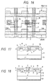
- Fig. 16 is a plan view of a pixel employing a conventional bipolar transistor sensor, wherein shown are an emitter area (constituting a first main electrode area) 1; an output line 2 composed for example of aluminum; a contact hole 3 for connecting the emitter area 1 with the output line 2; a base area (constituting a control electrode area) 4 for accumulating photoinduced charge; a drive line 5 composed for example of polysilicon for effecting the sensor operation of the pixel; an electrode 6 forming a capacitance C OX between the base area 4 and the drive line 5; a gate (control) electrode 7, formed in a part of the drive line 5, of a p-MOS transistor (indicated by a broken-lined area M in Fig. 17) of which source and drain areas are composed of the base areas of the adjacent pixels; and a thick oxide film (field oxide film) 8 for separating pixels.
- an emitter area consisttituting a first main electrode area
- an output line 2 composed for example of
- Figs. 17 and 18 are cross-sectional views respectively along lines X-X' and Y-Y' in Fig. 16.
- a thin oxide film 9 there are shown a thin oxide film 9; an n + layer 10 of a high impurity concentration for device isolation, for separating the pixel signals in the Y-Y' direction; an n - layer 11 of a low impurity concentration in which the depletion layer is to spread; a collector area 12 (constituting a second main electrode area); and an interlayer insulation film 13 for separating the wirings 2, 5.
- a resetting p-MOS transistor M (indicated by a broken-lined circle) is formed in the horizontal separating area between the pixels.
- the gate of said p-MOS transistor is turned on, the base areas 4 of two pixels adjacent along the X-X' direction are connected, whereby the resetting is achieved.
- the p-MOS transistor M serves as the pixel separating means.
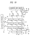
- Fig. 19 is an equivalent circuit diagram of the photoelectric converting device mentioned above.
- a pixel 21 is represented as composed of a bipolar phototransistor T, a capacitance C OX connected to the base, and a p-MOS transistor M.
- vertical output lines 22 connected to the emitters of the pixels 21; MOS transistors 23 for resetting the vertical output lines 23; accumulating capacitances 24 for accumulating the output signals from the pixels 21; MOS transistors 25 for transferring the output signals to the accumulating capacitances 24; MOS transistors 26 for transferring the output signals to a horizontal output line 27 in response to output signals of a horizontal shift register; a MOS transistor 28 for resetting the horizontal output line 27; a pre-amplifier 29; horizontal drive lines 30; buffer MOS transistors 31 for passing sensor drive pulses in response to the output of a vertical shift register; an emitter-follower circuit 32 for setting the source potential of the p-MOS transistors in order to effect clamping operations of the pixels 21; a p-MOS transistor 33 for setting the base potential of the emitter-follower circuit 32; a terminal 34 for applying a pulse to the gates of the MOS transistors 23; a terminal 35 for applying a pulse to the gates of the MOS transistors
- the two-dimensional solid-state image pickup device shown in Fig. 19 is of a type in which all the pixels can be reset at a time, and is preferably applied for example in a still video camera.
- the function of said two-dimensional solid-state image pickup device consists of a resetting operation, an accumulating operation, and a read-out operation, and the resetting operation is composed of a first resetting and a second resetting.
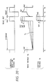
- Fig. 20 shows the potential change in various parts of the bipolar sensor in said operations, wherein shown are the potential ⁇ R of the horizontal drive line 30, base potential V B of the bipolar transistor, and emitter potential V E of the bipolar transistor T:
- the first resetting (t c - t d in Fig. 20) is to turn on the resetting p-MOS transistor M, thereby bringing the base area to a predetermined potential.
- a low-level pulse is applied to the terminal 37 shown in Fig. 19, thereby turning on the p-MOS transistor 33 to shift the output of the emitter-follower circuit 32 to a positive potential.
- Said output is supplied to the source of the p-MOS transistor M of each pixel, and, if the source potential becomes high enough, in comparison with the gate potential ⁇ R , for turning on the p-MOS transistor M, holes are injected through the p-MOS transistor to the base of the bipolar transistor T of each pixel.
- the second resetting shifts ⁇ R to a positive potential while maintaining the emitter of the bipolar transistor T in grounded state.
- a forward bias is applied between the base and the emitter, and the base potential is lowered by the recombination of electron and positive holes.
- the potential ⁇ R is returned to the ground potential, and an inverse bias is applied between the base and the emitter to initiate the next accumulating operation.
- a high-level pulse is applied to the terminal 34 shown in Fig. 19 to turn on the transistors 23 thereby grounding the vertical output lines 22.
- the vertical shift register is activated and reset pulses are applied to the terminal 36, thereby resetting the pixels in successive rows.
- the bases of the bipolar transistors T of all the pixels are brought to a predetermined potential in an inversely biased state, in preparation for the next accumulating operation.
- the accumulating operation starts at the completion of the above-explained resetting operation (t a in Fig. 20), when an inverse bias is applied between the base and the emitter of the bipolar transistor T.
- the base potential is elevated as the positive holes, generated by the incident light in the depletion layer between the base and the collector, are accumulated in the base area.
- the emitter of the bipolar transistor T is made floating, and the potential ⁇ R is shifted to a positive value to elevate the base potential by the capacitance coupling through C OX to create a forward bias state between the base and the emitter, whereby the read-out operation is initiated (t b in Fig. 20).
- the potential of the emitter connected to a capacitative load, reaches a certain potential difference to the base potential at the end of the read-out operation (t c in Fig. 20), the variations (V P1 , V P2 ) in the base potential at the accumulating operation appear on the emitter terminal.
- a low-level pulse is applied to the terminal 34 shown in Fig. 19 to turn off the MOS transistors 23, and, for each row selected by the output of the vertical shift register, a read-out pulse is supplied from the terminal 36 to accumulate the output signals in the accumulating capacitances 24 through the MOS transistors 25.
- accumulated output signals are subsequently transferred to the horizontal output line 27 through the transfer MOS transistors 26 selected in succession by the horizontal shift register, and released from the output terminal 38 through the pre-amplifier 29.
- the capacitative coupling with the base area is provided by the MOS capacitance (C OX ) utilizing a polysilicon electrode formed on the base area, but such configuration leads to the following second drawback of:
- document EP-A-0 277 016 discloses an electrode pattern with a protruding section contained in the electrode.
- a protruding section cannot be formed in a self-aligned manner with respect to its respective base area.
- this document discloses an electrode which extends from being opposed (over) a p-type base region to a portion being opposed (over) an area between neighboring p-type base regions. Stated in other words, the electrode strongly overlaps a first p-type base region while it does not overlap the adjacent p-type base region. Consequently, in connection with such a structure, no method for high accurately aligning this electrode in a sufficient reproducible manner is available and applicable, respectively.
- An object of the present invention is to provide a photoelectric converting device with improved fixed pattern noise reduction capability.
- Another object of the present invention is to provide a photoelectric converting device capable of varying the spreading of the depletion layer, through the control of the inverse bias amount of the control electrode area.
- Still another object of the present invention is to provide a photoelectric converting device with a reduced fluctuation in the capacitances among the pixels, by forming an electrode for applying the bias voltage at the read-out operation and a control electrode superposed thereon by a self-aligned process.
- the present invention is to reduce the fixed pattern noise resulting from the dark current, by regulation of the inverse bias amount in the rectifying junction in the photoelectric converting device.
- the present invention is to form an electrode between at least two adjacent semiconductor areas thereby forming an overlapping capacitance between said electrode and said at least two semiconductor areas by a self-aligning process and thus aligning the edge portion of said electrode with that of said semiconductor areas, and applying a signal having at least voltage levels to said electrode thereby effecting an accumulating operation, a read-out operation and a refreshing operation.
- the rectifying junction to be employed in the present invention can be a PN junction, a PI junction, a PIN junction or a Shottky junction, and, more specifically, the photoelectric converting cell is made of a diode or a bipolar transistor. In case of the bipolar transistor, the base-collector junction is used as the PN junction. It is also possible to form said cell by a junction field effect transistor or a static induction transistor, and to utilize the gate-channel junction or the gate-drain junction thereof as the PN junction.
- an example of the present application is featured by a fact that the potentials of the first main electrode area and the drive line are elevated during the light signal accumulating operation thereby elevating the potential of the control electrode area, and that the potential difference between the control electrode area and the second main electrode area is made smaller than that at the end of resetting of said control electrode area, or namely the potential of the control electrode area is made close to that of the second main electrode area, whereby the width of the depletion layer between the control electrode area and the second main electrode area is reduced.
- Also another example of the present application is featured by a fact that a first voltage, a second voltage larger than said first voltage, and a third voltage of a level between said first and second voltages are suitably applied to said drive line to reset the charge in said control electrode area, then to set the drive line at said third voltage before the completion of resetting thereby setting the control electrode area at a high potential, and to set said drive line at said third voltage during the light signal accumulating operation, whereby the potential of the control electrode area is made close to that of the second main electrode area and the width of the depletion layer between the control electrode area and the second main electrode area is reduced.
- Such reduction in the width of the depletion layer between the control electrode area and the second main electrode area allows to reduce the fixed pattern noise based on the dark current, thereby improving the S/N ratio without sacrificing the sensitivity.
- Also another example of the present application is featured by a fact that the photoelectric converting element is driven by the capacitance C GC formed by the control electrode of the gate-insulated resetting transistor and the control electrode area of the pixel area, whereby the capacitance C OX formed on the control electrode area in the prior art can be dispensed and a high S/N ratio can be attained in the sensor.
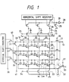
- Fig. 1 is an equivalent circuit diagram of a first example of the solid-state image pickup device.
- MOS transistors 14 for controlling the potentials of vertical output lines 22; a terminal 15 for applying a pulse to the gates of the MOS transistors 14; a power supply terminal 16 connected to the sources of the MOS transistor 14 and providing a reference voltage; MOS transistors 17 for controlling the potentials of horizontal drive lines 30; a terminal 18 for applying a pulse to the gates of the MOS transistors 17; a power supply terminal 19 connected to the sources of the MOS transistors 17 and providing a reference voltage; MOS transistors 39 for controlling the potentials of horizontal drive lines 30; a terminal 40 for applying a pulse to the gates of the MOS transistors 39; and a power supply terminal 41 connected to the sources of the MOS transistors 39 and providing a reference voltage.
- Fig. 2 is a timing chart showing pulses supplied to various terminals for driving the above-explained solid-state image pickup device, wherein it is assumed that the MOS transistors 14, 17, 33 are p-MOS transistors to be turned on when the gate is at the low level state, while the MOS transistors 23, 25, 39 are n-MOS transistors to be turned on when the gate is at the high level state.
- a high level pulse is applied to the terminal 34 to turn on the n-MOS transistors 23, thereby grounding the vertical lines and the emitters of the bipolar transistors.
- the n-MOS transistors 39 are turned on to provide the horizontal drive lines with a pulse for turning on the p-MOS transistors M of the pixels.
- a low level pulse is applied to the terminal 37.
- the p-MOS transistors M of the pixels are turned on, and the reference voltage for base resetting is supplied through the emitter-follower circuit 32 to set the bases of all the pixels to the reference potential (first resetting step).
- terminals 37 and 40 are respectively given a high level pulse and a low level pulse, whereby the p-MOS transistors M of the pixels are turned off and the bases of the pixels are maintained in a floating state.
- the reference voltage pulse is supplied to the terminal 36, in synchronization with the shift pulses of the vertical shift register, whereby a high level pulse is applied to the horizontal drive lines in succession.
- the bases of the bipolar transistors T of the pixels are forward biased to the emitters, by said pulse applied through the capacitance C OX .
- the base potentials are reset to an initial state (second resetting step).
- the pulses supplied to the terminals 15, 18 are simultaneously shifted to the low level state to turn on the p-MOS transistors 14, 17 thereby shifting the vertical output lines 22 and the horizontal drive lines 30 to the high level state.
- the base-collector inverse bias potential difference V BC becomes smaller than in the prior configuration.
- the MOS transistors 14, 17 are once turned off to shift the vertical output lines 22 and the horizontal drive lines 30 to the floating state, and then the terminals 34, 40 are shifted to the high level state to turn on the n-MOS transistors 23, 39 thereby returning the vertical output lines 22 and the horizontal drive lines 30 to the state at the end of the resetting operation.
- the (base thickness) + thickness of depletion layer between base and collector
- the resetting and read-out operations are same as in the prior art, so that the visible sensitivity is same as in the conventional device. Consequently the fixed pattern noise based on the dark current is reduced and the S/N ratio can be improved.
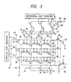
- Fig. 3 is an equivalent circuit diagram of a second example of the solid-state image pickup device, wherein same components as in Fig. 1 are represented by same symbols and will not be explained further.
- Fig. 3 there are shown a resistor 42 connecting the sources of the MOS transistors 14 and the power supply terminal 16; a resistor 43 connecting the MOS transistors 17 and the power supply terminal 19; and a resistor 45 connecting the sources of the MOS transistors 39 and the power supply terminal 41.
- resistors 42, 43 45 provides the following effect. If the potentials of the vertical output lines 22 and the horizontal drive lines 30 are rapidly raised in the start of the accumulating period, the potential difference therebetween becomes larger with a small time difference as said rising time becomes shorter, so that the margin in the driving timing has to be made smaller. For example, if the horizontal drive lines 30 are close to the high level potential while the vertical output lines 22 are close to the ground potential, the bipolar sensors of the pixels are turned on to generate base currents. On the other hand, if the vertical output lines 22 are close to the high level potential while the horizontal drive lines 30 are close to the ground potential, the base potentials are elevated whereby the p-MOS transistors M between the pixels are turned on to generate leak currents among the pixels.
- the presence of the resistors in the power supply for increasing the time constants realizes slower upshift and downshift of the potentials of the vertical output lines 22 and the horizontal drive lines 30, so that the difference of the potentials does not become large even with a slight difference in the driving time. Consequently the margin in the drive timing can be made larger.
- the resetting MOS transistors 23 which do not have the resistor in the power supply are turned on later than the MOS transistors 39, so that the enlargement in the potential difference can be prevented.
- the read-out operation can be achieved while the terminal 40 is given a high level pulse, namely while the MOS transistors 39 are turned on, and the reset pulse supplied to the terminal 36 can be applied to the sensors.
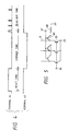
- Fig. 5 is a partial circuit diagram of a third embodiment of the solid-state image pickup device of the present invention, wherein all the components, except those explained in the following, are same as those in the second example shown in Fig. 3.
- MOS transistors 46 for controlling the potentials of the vertical output lines 22; a terminal 47 for applying a pulse to the gates of the MOS transistors 46; and a resistor 48 grounding the sources of the MOS transistors 46.
- the pulse supplied to the terminal 47 is upshiftes simultaneously with the pulse supplied to the terminal 40, in order that the MOS transistors 46, instead of the MOS transistors 23, shift the vertical output lines 22 to the ground potential prior to the end of the accumulating operation.
- Other functions are same as those in the second example.
- the base potential is elevated to generate a forward bias state between the base and the emitter or the collector.
- Such forward bias state between the base and the collector induces injection of holes into the collector and flow of such holes into the bases of other pixels, known as blooming phenomenon.
- the potential of the terminal 16 is selected slightly lower, for example by 0.5 V, than the collector potential. In this manner, when the sensor is irradiated by the strong light, the excessive holes are made to flow into the emitter instead of the collector.
- the sensors are driven in the same manner as in the 1st to 3rd embodiments.
- Fig. 6 is an equivalent circuit diagram of a 5th example of the solid-state image pickup device.
- the potentials of the horizontal drive lines 30 and the vertical output lines 22 are elevated in the accumulating operation to elevate the gate potential, thereby reducing the potential difference between the gate area and the collector area.
- voltages of three levels are applied to the horizontal drive lines for effecting the resetting, and, at the end thereof, the gate potential is set at a high level and is maintained at this level during the accumulating period, thereby reducing the potential difference between the gate area and the collector area in the accumulating operation.
- each horizontal drive line 30 is given a low- or high-level voltage through the MOS transistor 31, and is given a medium-level voltage through said MOS transistor 70.
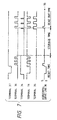
- the functions of this embodiment will be explained in the following, with reference to a timing chart shown in Fig. 7.
- the resetting, accumulating and read-out operations are similar to those in the foregoing embodiments, but, in the present example, the resetting is executed by controlling the base potential by the voltages of three levels, namely the low- and high-level voltages supplied to the terminal 36 and the medium-level voltage supplied to the terminal 72, and, at the end of the resetting, the horizontal drive lines 30 are set at the medium-level voltage. Then the terminal 71 is shifted to the high level potential to turn on the MOS transistors 70 during the accumulating period, thereby maintaining the horizontal drive lines 30 at said medium-level potential.
- the terminal 72 for example at V cc /2, it is rendered possible to set a high base potential and to set the base-collector inverse bias voltage in the bipolar transistors of the pixels smaller than in the prior art, at the end of the second resetting.
- the width of the depletion layer between the base and the collector during the accumulating period can be made smaller than in the prior art, and the fixed pattern noise based on the dark current can be reduced.
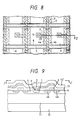
- Fig. 8 is a plan view of a pixel of a 6th example of the solid-state image pickup device
- Fig. 9 is a cross-sectional view of the device shown in Fig. 8.
- same components as those in Figs. 16 to 18 are represented by same symbols.
- Figs. 8 and 9 there are shown an n + emitter area 1 constituting a main electrode area; an Al wiring 2 constituting an emitter output line and a vertical output line; a contact hole 3 connecting the emitter area 1 with the Al wiring 2; a p-base area constituting a control electrode area; p + -areas 4a, 4b of a high impurity concentration, constituting parts of control electrode areas and serving as source and drain areas of a p-MOS transistor; a drive line 5 composed for example of polysilicon for effecting the sensor operation of the pixel; a polysilicon electrode 7 constituting the gate of the p-MOS transistor and composed of a part of the drive line 5, receiving a three-level signal; a SiO 2 layer 9 composed of a gate oxide film; an n - epitaxial layer 11 constituting a part of the collector area; a Si substrate 12 constituting the collector area; an interlayer insulation film 13; and a surface protective film 13'.
- the largest feature of the present embodiment lies in fact that the polysilicon wiring 5 is formed on the element isolating area 8, and that the capacitance C OX of the polysilicon gate MOS transistor conventionally formed on the p-base area 4 is dispensed with and is functionally replaced by a capacitance C GC formed by a polysilicon electrode 7 and p + -areas 4a, 4b.
- Fig. 10 is an equivalent circuit diagram of the present embodiment
- Fig. 11 is a cross-sectional view of the p-MOS transistor forming said capacitanct C GC .
- the gate-base capacitance C GC of the p-MOS transistor is utilized for elevating the base potential to the positive side, at the read-out and resetting operations.
- C GC ⁇ OX L D W/t OX wherein ⁇ OX is the dielectric constant of the gate oxide film, W is the gate length, and t OX is the thickness of the gate oxide film.
- the capacitance C GC is formed solely by the overlapping capacitance obtained by self alignment, the fluctuation in the capacitance among different pixels is reduced in comparison with that in the conventional configuration, whereby the fluctuations in the sensitivity and in the saturated voltage, and the fixed pattern noise can be reduced. Also the absence of polysilicon on the base area allows to improve the sensitivity to blue light and to reduce the dark current. Consequently the present embodiment can provide a photoelectric converting device with a reduced noise level, a higher sensitivity and an improved S/N ratio.
- Fig. 12 is a plan view of a 7th example of the solid-state image pickup device, wherein same components as those in the 1st embodiment are represented by same symbols, and will not be explained further.
- 4c, 4d indicate p - areas constituting source and drain.
- the present example employs p - areas of a low impurity concentration.
- C GC ⁇ t OX /( ⁇ OX L D W) + W S /( ⁇ S L D W) ⁇ -1 wherein W S is the width of the depletion layer, and ⁇ S is the dielectric constant of silicon.
- the present example enables a further increase in the sensitivity by the reduction of the base capacitance. It however is effective in case a large saturation voltage is not required, since the saturation voltage becomes smaller.
- Fig. 13 is a plan view of an 8th example of the solid-state image pickup device, wherein same components as those in the 1st and 2nd embodiments are represented by same symbols.
- the present example employs, in the source and drain areas of the p-MOS transistor, p + -areas 4a, 4b of a high impurity concentration and p - -areas 4c, 4d of a low impurity concentration in mixed manner, thereby reducing the capacitance C GC .
- the gate-base capacitance C GC can be arbitrarily varied by a change in the proportion of the p + areas 4a, 4b and the p - areas 4c, 4d.
- Fig. 14 is a plan view of a 9th example of the solid-state image pickup device, wherein same components as those in the 1st and 2nd examples are represented by same symbols.
- the impurity concentrations in the source and drain areas of the p-MOS transistors at the left and right sides of the pixel are made different. More specifically, a p - area 4c of low impurity concentration and a p + area 4b of high impurity concentration are employed as the source and drain areas of the p-MOS transistor. Also the present embodiment can reduce the gate-base capacitance C GC .
- Fig. 15 is a plan view of a 10th example of the solid-state image pickup device, wherein same components as those in the 1st and 2nd examples are represented by same symbols and will be omitted from the following description.
- V B1 (C GC + C OX )/(C GC + C OX + C BC + C BE ) x V R and this example is effective when a high saturation voltage is required.
- the 1st to 5th example are to elevate the potential of the control electrode area to reduce the potential difference between said control electrode area and the second main electrode area, thereby suppressing the dark current inducing the fixed pattern noise and realizing a photoelectric converting device of a high S/N ratio.
- a solid-state image pickup device When applied to a solid-state image pickup device, not only provides a high S/N ratio but also suppresses the crosstalk and the blooming.
- the 6th to 10th examples are to form a gate-insulated transistor by providing a control electrode, across an insulating film, on a semiconductor area between two control electrode areas of the adjacent photo-electric converting elements, also forming a capacitative coupling between said control electrode and at least one of said two control electrode areas and controlling the potential of said control electrode area through the potential control of said control electrode.
- This configuration allows to dispense with the capacitance C OX conventionally provided on the control electrode area, to improve the sensitivity, and to reduce the dark current and the fixed pattern noise.
- Fig. 21 is a block diagram of a signal processing system such as a communication system, a facsimile or a video recorder, employing the photoelectric converting device, wherein shown are an original OR, bearing image information; an imaging lens 601; and a photoelectric converting device 602 of the present invention.
- a signal processing system such as a communication system, a facsimile or a video recorder, employing the photoelectric converting device, wherein shown are an original OR, bearing image information; an imaging lens 601; and a photoelectric converting device 602 of the present invention.
- Said device can be of a simple device structure in case of the simple communication system, or of a line sensor in case of the facsimile, or an area sensor in case of the video recorder.
- a control circuit 603 including a central processing unit is connected to the device 602 through an input line 612, an output line 610 for driving said device 612, and a power supply line 611.
- a recording control circuit 604 is connected to a recording head 605 for recording information on a recording medium 606.
- Said recording head 605 is a magnetic head in case of the video recorder, or a thermal head or an ink jet head for discharging ink by thermal energy, in case of the facsimile.
- the recording head 605 may be replaced by a recording unit positioned in another location and connected through a cable.
Landscapes
- Engineering & Computer Science (AREA)
- Multimedia (AREA)
- Signal Processing (AREA)
- Solid State Image Pick-Up Elements (AREA)
- Transforming Light Signals Into Electric Signals (AREA)
Claims (1)
- Dispositif de conversion photoélectrique comportant une pluralité de cellules de conversion photoélectrique (21) comprenant chacune :caractérisé en ce que :une première zone semiconductrice (4, 4a) d'un premier type de conductivité, comprenant une région de source (4a) et une région de base (4),une région de drain (4b) du premier type de conductivité,une deuxième zone semiconductrice (11) d'un deuxième type de conductivité, qui est disposée entre lesdites régions de source et de drain, etune électrode de grille (7) disposée dans une région correspondant à la zone entre lesdites régions de source et de drain (4a) ;ladite électrode (7) est disposée sur les bords desdites régions de source et de drain (4a, 4b), ladite électrode (7) étant constituée par une formation auto-alignée de telle sorte que les deux bords de l'électrode (7) se chevauchent respectivement avec un bord de la région de source et de la région de drain (4a, 4b), de façon à former par conséquent deux capacités se chevauchant sensiblement égales (CGC) ; etladite capacité (CGC) est disposée de façon à commander le potentiel de ladite première zone semiconductrice (4a, 4b), de façon à réaliser par conséquent les opérations d'accumulation, de lecture et de remise à zéro.
Applications Claiming Priority (3)
| Application Number | Priority Date | Filing Date | Title |
|---|---|---|---|
| JP8305892 | 1992-03-06 | ||
| JP83058/92 | 1992-03-06 | ||
| JP8305892 | 1992-03-06 |
Publications (2)
| Publication Number | Publication Date |
|---|---|
| EP0559207A1 EP0559207A1 (fr) | 1993-09-08 |
| EP0559207B1 true EP0559207B1 (fr) | 2001-12-19 |
Family
ID=13791594
Family Applications (1)
| Application Number | Title | Priority Date | Filing Date |
|---|---|---|---|
| EP93103549A Expired - Lifetime EP0559207B1 (fr) | 1992-03-06 | 1993-03-05 | Dispositif de conversion photoélectrique |
Country Status (3)
| Country | Link |
|---|---|
| US (1) | US5406332A (fr) |
| EP (1) | EP0559207B1 (fr) |
| DE (1) | DE69331357T2 (fr) |
Families Citing this family (20)
| Publication number | Priority date | Publication date | Assignee | Title |
|---|---|---|---|---|
| JP3441761B2 (ja) * | 1993-05-28 | 2003-09-02 | キヤノン株式会社 | イメージセンサ |
| GB2289983B (en) * | 1994-06-01 | 1996-10-16 | Simage Oy | Imaging devices,systems and methods |
| JP3571770B2 (ja) * | 1994-09-16 | 2004-09-29 | キヤノン株式会社 | 光電変換装置 |
| JPH11503283A (ja) * | 1995-04-07 | 1999-03-23 | リットン システムズ カナダ リミテッド | 作動型マトリックス画像アレイのための読出し回路 |
| JP3432051B2 (ja) * | 1995-08-02 | 2003-07-28 | キヤノン株式会社 | 光電変換装置 |
| US5744807A (en) * | 1996-06-20 | 1998-04-28 | Xerox Corporation | Sensor array data line readout with reduced crosstalk |
| KR100262873B1 (ko) * | 1996-08-13 | 2000-08-01 | 네드위치 리차드 | 집적 전기 셔터를 갖는 캐패시터 결합된 바이폴라 액티브픽셀 센서 |
| US5786623A (en) * | 1996-10-22 | 1998-07-28 | Foveonics, Inc. | Bipolar-based active pixel sensor cell with metal contact and increased capacitive coupling to the base region |
| US5760458A (en) * | 1996-10-22 | 1998-06-02 | Foveonics, Inc. | Bipolar-based active pixel sensor cell with poly contact and increased capacitive coupling to the base region |
| EP0938810B1 (fr) * | 1996-11-12 | 2002-08-28 | California Institute Of Technology | Capteur d'images a semi-conducteurs a cryptage sur la puce |
| JP4036956B2 (ja) * | 1997-04-25 | 2008-01-23 | セイコーインスツル株式会社 | リニアイメージセンサ |
| US6529241B1 (en) | 1998-02-27 | 2003-03-04 | Intel Corporation | Photodetecting device supporting saturation detection and electronic shutter |
| US6590242B1 (en) * | 1999-02-25 | 2003-07-08 | Canon Kabushiki Kaisha | Light-receiving element and photoelectric conversion device |
| US7081607B1 (en) | 1999-10-05 | 2006-07-25 | Canon Kabushiki Kaisha | Solid state image pickup device and image pickup system |
| US7324144B1 (en) * | 1999-10-05 | 2008-01-29 | Canon Kabushiki Kaisha | Solid image pickup device, image pickup system and method of driving solid image pickup device |
| JP3667186B2 (ja) * | 2000-02-29 | 2005-07-06 | キヤノン株式会社 | 信号転送装置及びそれを用いた固体撮像装置 |
| JP3750502B2 (ja) * | 2000-08-03 | 2006-03-01 | ソニー株式会社 | 固体撮像装置およびカメラシステム |
| JP3962561B2 (ja) | 2001-07-12 | 2007-08-22 | キヤノン株式会社 | 固体撮像装置及びそれを用いた撮像システム |
| US8038654B2 (en) * | 2007-02-26 | 2011-10-18 | Becton, Dickinson And Company | Syringe having a hinged needle shield |
| JP2015056878A (ja) * | 2013-09-13 | 2015-03-23 | 株式会社東芝 | 固体撮像装置 |
Family Cites Families (16)
| Publication number | Priority date | Publication date | Assignee | Title |
|---|---|---|---|---|
| US4686554A (en) * | 1983-07-02 | 1987-08-11 | Canon Kabushiki Kaisha | Photoelectric converter |
| US4794443A (en) * | 1984-05-28 | 1988-12-27 | Canon Kabushiki Kaisha | Semiconductor device and process for producing same |
| DE3585516D1 (de) * | 1984-12-26 | 1992-04-09 | Canon Kk | Bildsensoranordnung. |
| JPH0646655B2 (ja) * | 1985-04-01 | 1994-06-15 | キヤノン株式会社 | 固体撮像装置 |
| CA1289242C (fr) * | 1985-11-13 | 1991-09-17 | Shigetoshi Sugawa | Methode et dispositif de conversion photoelectrique de la lumiere en un signal |
| JPH0812906B2 (ja) * | 1986-07-11 | 1996-02-07 | キヤノン株式会社 | 光電変換装置の製造方法 |
| JPH0644619B2 (ja) * | 1986-07-17 | 1994-06-08 | キヤノン株式会社 | 光電変換装置 |
| JPH084129B2 (ja) * | 1986-11-19 | 1996-01-17 | キヤノン株式会社 | 光電変換装置 |
| US4866293A (en) * | 1986-12-09 | 1989-09-12 | Canon Kabushiki Kaisha | Photoelectric converting apparatus to prevent the outflow of excess carriers |
| EP0277016B1 (fr) * | 1987-01-29 | 1998-04-15 | Canon Kabushiki Kaisha | Dispositif de conversion photovoltaique |
| US4922138A (en) * | 1987-05-25 | 1990-05-01 | Canon Kabushiki Kaisha | Scan circuit using a plural bootstrap effect for forming scan pulses |
| US4959723A (en) * | 1987-11-06 | 1990-09-25 | Canon Kabushiki Kaisha | Solid state image pickup apparatus having multi-phase scanning pulse to read out accumulated signal |
| US4849470A (en) * | 1988-10-31 | 1989-07-18 | Advanced Protection Technologies, Inc. | Polyurethane systems especially adapted for surge suppression |
| US5146339A (en) * | 1989-11-21 | 1992-09-08 | Canon Kabushiki Kaisha | Photoelectric converting apparatus employing Darlington transistor readout |
| DE69030159T2 (de) * | 1989-12-14 | 1997-07-03 | Canon Kk | Photoelektrische Umwandlervorrichtung mit verbessertem Rückstelltransistor und Informationsverarbeitungsgerät, welches diese verwendet |
| EP0473294B1 (fr) * | 1990-08-07 | 2004-09-22 | Canon Kabushiki Kaisha | Dispositif de photo conversion |
-
1993
- 1993-03-04 US US08/026,011 patent/US5406332A/en not_active Expired - Fee Related
- 1993-03-05 EP EP93103549A patent/EP0559207B1/fr not_active Expired - Lifetime
- 1993-03-05 DE DE69331357T patent/DE69331357T2/de not_active Expired - Fee Related
Also Published As
| Publication number | Publication date |
|---|---|
| DE69331357T2 (de) | 2002-07-04 |
| DE69331357D1 (de) | 2002-01-31 |
| EP0559207A1 (fr) | 1993-09-08 |
| US5406332A (en) | 1995-04-11 |
Similar Documents
| Publication | Publication Date | Title |
|---|---|---|
| US5406332A (en) | Photoelectric converting device | |
| US5283428A (en) | Photoelectric converting device and information processing apparatus employing the same | |
| US7227208B2 (en) | Solid-state image pickup apparatus | |
| CA1257922A (fr) | Convertisseur photoelectrique | |
| US4878120A (en) | Solid state image sensor including static induction transistor with gate surrounding source and/or drain | |
| EP0277016B1 (fr) | Dispositif de conversion photovoltaique | |
| JP3697769B2 (ja) | 光電変換素子及び光電変換装置 | |
| US4831454A (en) | Image sensor device having plural photoelectric converting elements | |
| USRE34309E (en) | Image sensor device having plural photoelectric converting elements | |
| US4450484A (en) | Solid states image sensor array having circuit for suppressing image blooming and smear | |
| US20020017661A1 (en) | Charge transfer apparatus | |
| US4688098A (en) | Solid state image sensor with means for removing excess photocharges | |
| US5274459A (en) | Solid state image sensing device with a feedback gate transistor at each photo-sensing section | |
| JP4750980B2 (ja) | 電荷結合デバイスにおける暗電流低減方法 | |
| KR100245245B1 (ko) | 증폭형 광전변환소자 및 이를 사용한 증폭형 고체촬상장치 | |
| US6445414B1 (en) | Solid-state image pickup device having vertical overflow drain and resistive gate charge transfer device and method of controlling thereof | |
| US5416345A (en) | Solid-state image sensor with dark-current eliminator | |
| EP0576022B1 (fr) | Dispositif de conversion photo-électrique et son procédé de commande | |
| Nakamura et al. | A new MOS image sensor operating in a non-destructive readout mode | |
| US4677453A (en) | Solid state image sensor | |
| EP0055114B1 (fr) | Dispositif capteur d'images à semiconducteurs | |
| JPH0430192B2 (fr) | ||
| JPH0678219A (ja) | 光電変換装置 | |
| JP2594923B2 (ja) | 固体撮像素子 | |
| JP2758739B2 (ja) | 固体撮像装置の駆動方法 |
Legal Events
| Date | Code | Title | Description |
|---|---|---|---|
| PUAI | Public reference made under article 153(3) epc to a published international application that has entered the european phase |
Free format text: ORIGINAL CODE: 0009012 |
|
| AK | Designated contracting states |
Kind code of ref document: A1 Designated state(s): DE FR GB |
|
| 17P | Request for examination filed |
Effective date: 19940125 |
|
| 17Q | First examination report despatched |
Effective date: 19980409 |
|
| GRAG | Despatch of communication of intention to grant |
Free format text: ORIGINAL CODE: EPIDOS AGRA |
|
| GRAG | Despatch of communication of intention to grant |
Free format text: ORIGINAL CODE: EPIDOS AGRA |
|
| GRAH | Despatch of communication of intention to grant a patent |
Free format text: ORIGINAL CODE: EPIDOS IGRA |
|
| GRAH | Despatch of communication of intention to grant a patent |
Free format text: ORIGINAL CODE: EPIDOS IGRA |
|
| GRAA | (expected) grant |
Free format text: ORIGINAL CODE: 0009210 |
|
| AK | Designated contracting states |
Kind code of ref document: B1 Designated state(s): DE FR GB |
|
| PG25 | Lapsed in a contracting state [announced via postgrant information from national office to epo] |
Ref country code: FR Free format text: LAPSE BECAUSE OF FAILURE TO SUBMIT A TRANSLATION OF THE DESCRIPTION OR TO PAY THE FEE WITHIN THE PRESCRIBED TIME-LIMIT Effective date: 20011219 |
|
| REG | Reference to a national code |
Ref country code: GB Ref legal event code: IF02 |
|
| REF | Corresponds to: |
Ref document number: 69331357 Country of ref document: DE Date of ref document: 20020131 |
|
| PG25 | Lapsed in a contracting state [announced via postgrant information from national office to epo] |
Ref country code: GB Free format text: LAPSE BECAUSE OF NON-PAYMENT OF DUE FEES Effective date: 20020319 |
|
| EN | Fr: translation not filed | ||
| PLBE | No opposition filed within time limit |
Free format text: ORIGINAL CODE: 0009261 |
|
| GBPC | Gb: european patent ceased through non-payment of renewal fee |
Effective date: 20020319 |
|
| 26N | No opposition filed | ||
| PGFP | Annual fee paid to national office [announced via postgrant information from national office to epo] |
Ref country code: DE Payment date: 20060302 Year of fee payment: 14 |
|
| PG25 | Lapsed in a contracting state [announced via postgrant information from national office to epo] |
Ref country code: DE Free format text: LAPSE BECAUSE OF NON-PAYMENT OF DUE FEES Effective date: 20071002 |