EP0559246A2 - Panneau métallique poreux revêtu - Google Patents
Panneau métallique poreux revêtu Download PDFInfo
- Publication number
- EP0559246A2 EP0559246A2 EP93200246A EP93200246A EP0559246A2 EP 0559246 A2 EP0559246 A2 EP 0559246A2 EP 93200246 A EP93200246 A EP 93200246A EP 93200246 A EP93200246 A EP 93200246A EP 0559246 A2 EP0559246 A2 EP 0559246A2
- Authority
- EP
- European Patent Office
- Prior art keywords
- pores
- panel
- shield
- lamina
- inlet
- Prior art date
- Legal status (The legal status is an assumption and is not a legal conclusion. Google has not performed a legal analysis and makes no representation as to the accuracy of the status listed.)
- Granted
Links
Images
Classifications
-
- F—MECHANICAL ENGINEERING; LIGHTING; HEATING; WEAPONS; BLASTING
- F23—COMBUSTION APPARATUS; COMBUSTION PROCESSES
- F23R—GENERATING COMBUSTION PRODUCTS OF HIGH PRESSURE OR HIGH VELOCITY, e.g. GAS-TURBINE COMBUSTION CHAMBERS
- F23R3/00—Continuous combustion chambers using liquid or gaseous fuel
- F23R3/002—Wall structures
-
- C—CHEMISTRY; METALLURGY
- C23—COATING METALLIC MATERIAL; COATING MATERIAL WITH METALLIC MATERIAL; CHEMICAL SURFACE TREATMENT; DIFFUSION TREATMENT OF METALLIC MATERIAL; COATING BY VACUUM EVAPORATION, BY SPUTTERING, BY ION IMPLANTATION OR BY CHEMICAL VAPOUR DEPOSITION, IN GENERAL; INHIBITING CORROSION OF METALLIC MATERIAL OR INCRUSTATION IN GENERAL
- C23C—COATING METALLIC MATERIAL; COATING MATERIAL WITH METALLIC MATERIAL; SURFACE TREATMENT OF METALLIC MATERIAL BY DIFFUSION INTO THE SURFACE, BY CHEMICAL CONVERSION OR SUBSTITUTION; COATING BY VACUUM EVAPORATION, BY SPUTTERING, BY ION IMPLANTATION OR BY CHEMICAL VAPOUR DEPOSITION, IN GENERAL
- C23C4/00—Coating by spraying the coating material in the molten state, e.g. by flame, plasma or electric discharge
- C23C4/01—Selective coating, e.g. pattern coating, without pre-treatment of the material to be coated
-
- C—CHEMISTRY; METALLURGY
- C23—COATING METALLIC MATERIAL; COATING MATERIAL WITH METALLIC MATERIAL; CHEMICAL SURFACE TREATMENT; DIFFUSION TREATMENT OF METALLIC MATERIAL; COATING BY VACUUM EVAPORATION, BY SPUTTERING, BY ION IMPLANTATION OR BY CHEMICAL VAPOUR DEPOSITION, IN GENERAL; INHIBITING CORROSION OF METALLIC MATERIAL OR INCRUSTATION IN GENERAL
- C23C—COATING METALLIC MATERIAL; COATING MATERIAL WITH METALLIC MATERIAL; SURFACE TREATMENT OF METALLIC MATERIAL BY DIFFUSION INTO THE SURFACE, BY CHEMICAL CONVERSION OR SUBSTITUTION; COATING BY VACUUM EVAPORATION, BY SPUTTERING, BY ION IMPLANTATION OR BY CHEMICAL VAPOUR DEPOSITION, IN GENERAL
- C23C4/00—Coating by spraying the coating material in the molten state, e.g. by flame, plasma or electric discharge
- C23C4/18—After-treatment
- C23C4/185—Separation of the coating from the substrate
-
- F—MECHANICAL ENGINEERING; LIGHTING; HEATING; WEAPONS; BLASTING
- F01—MACHINES OR ENGINES IN GENERAL; ENGINE PLANTS IN GENERAL; STEAM ENGINES
- F01D—NON-POSITIVE DISPLACEMENT MACHINES OR ENGINES, e.g. STEAM TURBINES
- F01D5/00—Blades; Blade-carrying members; Heating, heat-insulating, cooling or antivibration means on the blades or the members
- F01D5/12—Blades
- F01D5/28—Selecting particular materials; Particular measures relating thereto; Measures against erosion or corrosion
- F01D5/288—Protective coatings for blades
-
- F—MECHANICAL ENGINEERING; LIGHTING; HEATING; WEAPONS; BLASTING
- F05—INDEXING SCHEMES RELATING TO ENGINES OR PUMPS IN VARIOUS SUBCLASSES OF CLASSES F01-F04
- F05D—INDEXING SCHEME FOR ASPECTS RELATING TO NON-POSITIVE-DISPLACEMENT MACHINES OR ENGINES, GAS-TURBINES OR JET-PROPULSION PLANTS
- F05D2260/00—Function
- F05D2260/20—Heat transfer, e.g. cooling
- F05D2260/202—Heat transfer, e.g. cooling by film cooling
-
- Y—GENERAL TAGGING OF NEW TECHNOLOGICAL DEVELOPMENTS; GENERAL TAGGING OF CROSS-SECTIONAL TECHNOLOGIES SPANNING OVER SEVERAL SECTIONS OF THE IPC; TECHNICAL SUBJECTS COVERED BY FORMER USPC CROSS-REFERENCE ART COLLECTIONS [XRACs] AND DIGESTS
- Y10—TECHNICAL SUBJECTS COVERED BY FORMER USPC
- Y10T—TECHNICAL SUBJECTS COVERED BY FORMER US CLASSIFICATION
- Y10T29/00—Metal working
- Y10T29/49—Method of mechanical manufacture
- Y10T29/49616—Structural member making
- Y10T29/49623—Static structure, e.g., a building component
- Y10T29/49629—Panel
-
- Y—GENERAL TAGGING OF NEW TECHNOLOGICAL DEVELOPMENTS; GENERAL TAGGING OF CROSS-SECTIONAL TECHNOLOGIES SPANNING OVER SEVERAL SECTIONS OF THE IPC; TECHNICAL SUBJECTS COVERED BY FORMER USPC CROSS-REFERENCE ART COLLECTIONS [XRACs] AND DIGESTS
- Y10—TECHNICAL SUBJECTS COVERED BY FORMER USPC
- Y10T—TECHNICAL SUBJECTS COVERED BY FORMER US CLASSIFICATION
- Y10T29/00—Metal working
- Y10T29/49—Method of mechanical manufacture
- Y10T29/49826—Assembling or joining
- Y10T29/49888—Subsequently coating
Definitions
- This invention relates to coated porous metal panels and to a method of making such a panel.
- Porous metal panels are described in United States patents US-A-3,584,972 and US-A-4,004,056. United States patents US-A-4,338,360 and US-A-5,130,163 describe methods of applying thermal barrier coating on porous metal panels with minimum deposit of coating material in the pores of the panel.
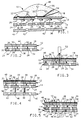
- the coated porous metal panel includes a first outer surface having a pattern of discharge pores therein, a second outer surface having a pattern of inlet pores therein laterally offset from the discharge pores and connected to the discharge pores through an internal chamber of the panel, and a shield lamina mechanically clamped against the second outer surface.
- the shield lamina preferably has a plurality of shield holes arrayed in the same pattern as the inlet pores so that when the shield lamina is in place, the inlet pores are exposed to a source of coolant gas.
- the panel preferably further includes a plurality of extraction passages behind respective ones of the discharge pores and opening through the second outer surface. When the shield lamina is in place, the extraction passages are blocked to foreclose entry of coolant gas into the extraction passages.
- coating material is sprayed generally perpendicularly to the first outer surface with the shield lamina not in place. Most of the coating material deposits on the first outer surface to form a coating thereon. Surplus coating material entering the discharge pores passes completely through the panel by way of the extraction passages and is collected behind the second outer surface. After the coating is applied, the shield lamina is mechanically clamped against the second outer surface to block the extraction passages.
- the second lamina 14 has an outer surface 24 forming a second outer surface of the panel 10 which is adapted for exposure to a source of coolant gas under pressure, not shown.
- the side of the second lamina opposite the outer surface 24 is etched or chemically machined to form an inner surface 26 interrupted by a plurality of integrally formed raised pedestals 28 each having a flat bonding surface 30 thereon.
- the second lamina 14 is diffusion bonded to the first lamina 12 at the abutting interfaces between the inner surface 20 and the boding surfaces 30 on the pedestals 28.
- the inner surfaces 20, 26 of the first and second laminas are spaced apart by the pedestals 28 and form therebetween an internal chamber 32 of the porous metal panel.
- the second lamina 14 has a plurality of inlet pores 34 passing therethrough arrayed in a regular second grid or pattern which is laterally offset relative to the first pattern of the discharge pores 22. Accordingly, each of the inlet pores 34 is laterally offset relative to each of the discharge pores 22 so that gas flow from the inlet pores to the discharge pores is constrained to follow tortuous flow paths through the internal chamber 32.
- the second lamina 14 further includes a plurality of extraction passages 36 passing therethrough arrayed in the first pattern so that each of the discharge pores 22 has directly behind it one of the extraction passages 36.
- a plurality of cylindrical rivet bodies 44 are welded or otherwise rigidly attached to the second lamina 14 substantially perpendicularly to the outer surface 24 thereof.
- the rivet bodies 44 are received in a corresponding plurality of clearance holes 46 in the shield lamina 16 when the inner surface 38 of the shield lamina is juxtaposed the outer surface 24 of the second lamina.
- a mounting bracket 47 may conveniently be fitted over the rivet bodies 44 against the outer surface 40 of the shield lamina for mounting the porous metal panel 10 on a support structure (not shown). Heads are formed on the rivet bodies 44 rigidly to secure together the shield lamina 16, the bracket 47, and the first and second laminas 12,14.
- the shield pores 42 overlay the inlet pores 34 for maintaining exposure of the inlet pores to the source of coolant gas under pressure.
- the remaining, solid portion of the shield lamina 16 blocks the extraction passages 36 to prevent entry of coolant gas into the extraction passages though the outer surface 24 of the second lamina.
- coolant gas under pressure enters the inlet pores 34 through the shield pores 42, circulates in tortuous paths through the internal chamber 32 for cooling the panel by convection, and exits through the discharge pores 22 to form a protective film between the panel and the heat source.
- a thermally resistant coating 48 is applied to the porous metal panel 10 by a method including the steps of mechanical surface preparation and spray coating. The aforesaid steps are performed with the shield lamina 16 not attached and may include grit blasting the outer surface 18 of the first lamina and spray application from spray apparatus 52.
- the coating 48 may include a bond coat 54 such as NiCrAlY on the grit-blasted outer surface 18 and a top coat 56 such as Yttria-stabilized zirconia over the bond coat.
- the extraction passages 36 permit use of other techniques for precluding deposit of surplus coating material in the internal chamber 32 and in the discharge and inlet pores 22, 34.
- mechanical blockers such as pins may be inserted into the extraction passages 36 from behind the second lamina 14. The pins may extend to just beyond the outer surface 18 completely to preclude entry of surplus coating material into the discharge pores. Then, at the conclusion of the spray operations, the pins are withdrawn to expose the discharge pores and the shield lamina is attached as described above.
- a mask may be introduced into the extraction passages to fill the discharge pores from behind. The mask precludes entry of surplus coating material into the discharge pores and may be chemically or thermally removed following coating.
Landscapes
- Engineering & Computer Science (AREA)
- Chemical & Material Sciences (AREA)
- Mechanical Engineering (AREA)
- Materials Engineering (AREA)
- Plasma & Fusion (AREA)
- Physics & Mathematics (AREA)
- General Engineering & Computer Science (AREA)
- Chemical Kinetics & Catalysis (AREA)
- Metallurgy (AREA)
- Organic Chemistry (AREA)
- Combustion & Propulsion (AREA)
- Laminated Bodies (AREA)
- Coating By Spraying Or Casting (AREA)
- Application Of Or Painting With Fluid Materials (AREA)
- Chemical Treatment Of Metals (AREA)
Applications Claiming Priority (2)
| Application Number | Priority Date | Filing Date | Title |
|---|---|---|---|
| US07/843,033 US5195243A (en) | 1992-02-28 | 1992-02-28 | Method of making a coated porous metal panel |
| US843033 | 2004-05-11 |
Publications (3)
| Publication Number | Publication Date |
|---|---|
| EP0559246A2 true EP0559246A2 (fr) | 1993-09-08 |
| EP0559246A3 EP0559246A3 (fr) | 1994-04-20 |
| EP0559246B1 EP0559246B1 (fr) | 1996-04-10 |
Family
ID=25288896
Family Applications (1)
| Application Number | Title | Priority Date | Filing Date |
|---|---|---|---|
| EP93200246A Expired - Lifetime EP0559246B1 (fr) | 1992-02-28 | 1993-02-01 | Panneau métallique poreux revêtu |
Country Status (5)
| Country | Link |
|---|---|
| US (1) | US5195243A (fr) |
| EP (1) | EP0559246B1 (fr) |
| JP (1) | JP2904669B2 (fr) |
| CA (1) | CA2087698C (fr) |
| DE (1) | DE69302118T2 (fr) |
Cited By (2)
| Publication number | Priority date | Publication date | Assignee | Title |
|---|---|---|---|---|
| EP0893653A3 (fr) * | 1997-07-21 | 2000-03-01 | General Electric Company | Revêtements protectifs pour des éléments des combusteurs de turbine |
| EP1293584A1 (fr) * | 2001-09-18 | 2003-03-19 | General Electric Company | Procédé et dispositif de masquage |
Families Citing this family (11)
| Publication number | Priority date | Publication date | Assignee | Title |
|---|---|---|---|---|
| CA2154156C (fr) * | 1993-02-02 | 2005-04-26 | Edward D. Suski | Carte de circuit a grilles de blindage et sa methode de fabrication |
| US5334800A (en) * | 1993-07-21 | 1994-08-02 | Parlex Corporation | Flexible shielded circuit board |
| US5675299A (en) * | 1996-03-25 | 1997-10-07 | Ast Research, Inc. | Bidirectional non-solid impedance controlled reference plane requiring no conductor to grid alignment |
| US6617003B1 (en) | 2000-11-06 | 2003-09-09 | General Electric Company | Directly cooled thermal barrier coating system |
| DE10261071A1 (de) * | 2002-12-24 | 2004-07-08 | Rolls-Royce Deutschland Ltd & Co Kg | Brennkammerwandelement für eine Gasturbine |
| JP4543715B2 (ja) * | 2004-03-23 | 2010-09-15 | 日産自動車株式会社 | エンジンフード構造体 |
| US7717677B1 (en) | 2007-01-31 | 2010-05-18 | Florida Turbine Technologies, Inc. | Multi-metering and diffusion transpiration cooled airfoil |
| US7766617B1 (en) | 2007-03-06 | 2010-08-03 | Florida Turbine Technologies, Inc. | Transpiration cooled turbine airfoil |
| CA2904200A1 (fr) * | 2013-03-05 | 2014-09-12 | Rolls-Royce Corporation | Tuile de chambre de combustion a effusion, convexion, impact a double paroi |
| WO2015047472A2 (fr) * | 2013-06-14 | 2015-04-02 | United Technologies Corporation | Augmentation du refroidissement d'une surface de panneau conducteur pour chambre de combustion de moteur à turbine à gaz |
| EP2995863B1 (fr) * | 2014-09-09 | 2018-05-23 | United Technologies Corporation | Brûleur à paroi unique pour un moteur à turbine à gaz et procédé de fabrication |
Family Cites Families (8)
| Publication number | Priority date | Publication date | Assignee | Title |
|---|---|---|---|---|
| JPS55138294A (en) * | 1979-04-11 | 1980-10-28 | Matsushita Electric Industrial Co Ltd | Method of forming through hole connector |
| US4426762A (en) * | 1979-08-28 | 1984-01-24 | Commissariat A L'energie Atomique | Method for selectively obturating at least one end of a structural module |
| US4338360A (en) * | 1980-05-01 | 1982-07-06 | General Motors Corporation | Method for coating porous metal structure |
| AT368283B (de) * | 1980-11-07 | 1982-09-27 | Philips Nv | Duesenplatte fuer einen tintenstrahlschreibkopf und verfahren zur herstellung einer solchen duesen- platte |
| US4751962A (en) * | 1986-02-10 | 1988-06-21 | General Motors Corporation | Temperature responsive laminated porous metal panel |
| US4803110A (en) * | 1986-09-15 | 1989-02-07 | International Business Machines Corporation | Coated mask for photolithographic construction of electric circuits |
| US4889776A (en) * | 1987-08-17 | 1989-12-26 | Barson Corporation | Refractory metal composite coated article |
| US5111579A (en) * | 1989-12-14 | 1992-05-12 | Steelcase Inc. | Method for making a frameless acoustic cover panel |
-
1992
- 1992-02-28 US US07/843,033 patent/US5195243A/en not_active Expired - Lifetime
-
1993
- 1993-01-20 CA CA002087698A patent/CA2087698C/fr not_active Expired - Lifetime
- 1993-02-01 EP EP93200246A patent/EP0559246B1/fr not_active Expired - Lifetime
- 1993-02-01 DE DE69302118T patent/DE69302118T2/de not_active Expired - Fee Related
- 1993-03-01 JP JP5040074A patent/JP2904669B2/ja not_active Expired - Fee Related
Cited By (3)
| Publication number | Priority date | Publication date | Assignee | Title |
|---|---|---|---|---|
| EP0893653A3 (fr) * | 1997-07-21 | 2000-03-01 | General Electric Company | Revêtements protectifs pour des éléments des combusteurs de turbine |
| US6393828B1 (en) | 1997-07-21 | 2002-05-28 | General Electric Company | Protective coatings for turbine combustion components |
| EP1293584A1 (fr) * | 2001-09-18 | 2003-03-19 | General Electric Company | Procédé et dispositif de masquage |
Also Published As
| Publication number | Publication date |
|---|---|
| DE69302118T2 (de) | 1996-10-02 |
| EP0559246A3 (fr) | 1994-04-20 |
| US5195243A (en) | 1993-03-23 |
| JPH0649678A (ja) | 1994-02-22 |
| DE69302118D1 (de) | 1996-05-15 |
| EP0559246B1 (fr) | 1996-04-10 |
| JP2904669B2 (ja) | 1999-06-14 |
| CA2087698C (fr) | 1998-06-23 |
| CA2087698A1 (fr) | 1993-08-29 |
Similar Documents
| Publication | Publication Date | Title |
|---|---|---|
| EP0559246B1 (fr) | Panneau métallique poreux revêtu | |
| EP1180604B1 (fr) | Bloc de distribution laminé pour une microsoupape | |
| EP0357020B1 (fr) | Fabrication de têtes d'impresson à jet d'encre par soudage par diffusion et brasage | |
| CA2292384A1 (fr) | Renouvellement d'un systeme de revetement d'isolation thermique | |
| EP0357019B1 (fr) | Brasage de composants de têtes d'impression à jet d'encre utilisant des couches minces de matière de brasage | |
| CA2481111C (fr) | Processus de masquage de trous de refroidissement d'un element de turbine a gaz | |
| US6582194B1 (en) | Gas-turbine blade and method of manufacturing a gas-turbine blade | |
| EP0650754B1 (fr) | Septum de filtre | |
| CA2084390C (fr) | Tuyere ablative pour tete d'impression a jet d'encre | |
| US6444331B2 (en) | Roughened bond coats for a thermal barrier coating system and method for producing | |
| US6602053B2 (en) | Cooling structure and method of manufacturing the same | |
| KR100512407B1 (ko) | 천이 액상 접합에 의한 연소터빈 부품을 형성하는 방법 | |
| JP2002529289A (ja) | 小滴付着装置 | |
| EP0863226A1 (fr) | Support modulaire pour installation de revêtement | |
| EP0483946A1 (fr) | Cache résistant à de hautes températures | |
| CA2057954A1 (fr) | Methode de revetement de la surface d'un stratifie poreux | |
| US4426762A (en) | Method for selectively obturating at least one end of a structural module | |
| JP3631189B2 (ja) | タービンブレードを保持するための工具 | |
| EP0819536A3 (fr) | Tête d'éjection de liquide, procédé de fabrication d'une telle tête d'éjection de liquide, cartouche de tête d'éjection de liquide et appareil d'éjection de liquide | |
| KR950014047B1 (ko) | 알루미늄제 열교환기코어 및 그 납땜공법에 있어서의 플럭스 도포방법 | |
| US5968299A (en) | Foil coating on a local region of a component and its method of production and installation | |
| EP0491492B1 (fr) | Méthode et appareil pour niveler de la soudure sur plaquettes à circuit imprimé | |
| GB1586265A (en) | Solder bonding of surfaces | |
| US6261422B1 (en) | Production of hollowed/channeled protective thermal-barrier coatings functioning as heat-exchangers | |
| RU96119402A (ru) | Способ пайки алюминия с жаропрочными сталями и сплавами |
Legal Events
| Date | Code | Title | Description |
|---|---|---|---|
| PUAI | Public reference made under article 153(3) epc to a published international application that has entered the european phase |
Free format text: ORIGINAL CODE: 0009012 |
|
| AK | Designated contracting states |
Kind code of ref document: A2 Designated state(s): DE FR GB |
|
| PUAL | Search report despatched |
Free format text: ORIGINAL CODE: 0009013 |
|
| AK | Designated contracting states |
Kind code of ref document: A3 Designated state(s): DE FR GB |
|
| 17P | Request for examination filed |
Effective date: 19940606 |
|
| 17Q | First examination report despatched |
Effective date: 19950413 |
|
| GRAA | (expected) grant |
Free format text: ORIGINAL CODE: 0009210 |
|
| AK | Designated contracting states |
Kind code of ref document: B1 Designated state(s): DE FR GB |
|
| REF | Corresponds to: |
Ref document number: 69302118 Country of ref document: DE Date of ref document: 19960515 |
|
| ET | Fr: translation filed | ||
| PLBE | No opposition filed within time limit |
Free format text: ORIGINAL CODE: 0009261 |
|
| STAA | Information on the status of an ep patent application or granted ep patent |
Free format text: STATUS: NO OPPOSITION FILED WITHIN TIME LIMIT |
|
| 26N | No opposition filed | ||
| REG | Reference to a national code |
Ref country code: GB Ref legal event code: IF02 |
|
| PGFP | Annual fee paid to national office [announced via postgrant information from national office to epo] |
Ref country code: DE Payment date: 20090225 Year of fee payment: 17 |
|
| PGFP | Annual fee paid to national office [announced via postgrant information from national office to epo] |
Ref country code: GB Payment date: 20090302 Year of fee payment: 17 |
|
| PGFP | Annual fee paid to national office [announced via postgrant information from national office to epo] |
Ref country code: FR Payment date: 20090224 Year of fee payment: 17 |
|
| GBPC | Gb: european patent ceased through non-payment of renewal fee |
Effective date: 20100201 |
|
| REG | Reference to a national code |
Ref country code: FR Ref legal event code: ST Effective date: 20101029 |
|
| PG25 | Lapsed in a contracting state [announced via postgrant information from national office to epo] |
Ref country code: FR Free format text: LAPSE BECAUSE OF NON-PAYMENT OF DUE FEES Effective date: 20100301 |
|
| PG25 | Lapsed in a contracting state [announced via postgrant information from national office to epo] |
Ref country code: DE Free format text: LAPSE BECAUSE OF NON-PAYMENT OF DUE FEES Effective date: 20100901 |
|
| PG25 | Lapsed in a contracting state [announced via postgrant information from national office to epo] |
Ref country code: GB Free format text: LAPSE BECAUSE OF NON-PAYMENT OF DUE FEES Effective date: 20100201 |