EP0559314A2 - LAN FDDI standard avec voie alternative - Google Patents
LAN FDDI standard avec voie alternative Download PDFInfo
- Publication number
- EP0559314A2 EP0559314A2 EP93300333A EP93300333A EP0559314A2 EP 0559314 A2 EP0559314 A2 EP 0559314A2 EP 93300333 A EP93300333 A EP 93300333A EP 93300333 A EP93300333 A EP 93300333A EP 0559314 A2 EP0559314 A2 EP 0559314A2
- Authority
- EP
- European Patent Office
- Prior art keywords
- node
- data
- port
- input
- nodes
- Prior art date
- Legal status (The legal status is an assumption and is not a legal conclusion. Google has not performed a legal analysis and makes no representation as to the accuracy of the status listed.)
- Withdrawn
Links
Images



Classifications
-
- H—ELECTRICITY
- H04—ELECTRIC COMMUNICATION TECHNIQUE
- H04L—TRANSMISSION OF DIGITAL INFORMATION, e.g. TELEGRAPHIC COMMUNICATION
- H04L12/00—Data switching networks
- H04L12/28—Data switching networks characterised by path configuration, e.g. LAN [Local Area Networks] or WAN [Wide Area Networks]
- H04L12/42—Loop networks
- H04L12/427—Loop networks with decentralised control
- H04L12/433—Loop networks with decentralised control with asynchronous transmission, e.g. token ring, register insertion
Definitions
- This invention relates to local area communication networks, and more particularly to local area networks (LAN) according to ANSI Fiber Distributed Data Interface (FDDI) standards, which LAN are arranged for enhanced reliability in adverse environments.
- LAN local area networks
- FDDI Fiber Distributed Data Interface
- Modern vehicles such as aircraft, ships and the like include sophisticated computer systems for sensing the environment, evaluating the sensed information, and for controlling the vehicle andor its payload in response to the evaluations.
- Such vehicles, and military equipment whether fixed or mobile, require highly reliable communications among the sensors, evaluation equipment, and the controlled devices. The reliability is often provided, at least in part, by redundancy.
- redundant computers for performing the evaluations, and redundant sensors and controlled devices, if possible, the interconnections should also be redundant.
- there may be a relatively large number of sensors including a plurality of radar, sonar, infrared and other sensors, all of which must be interconnected with command centers and with evaluation computers, and with guns, missiles and their controllers.
- each computer including the redundant computer
- each computer is required to provide a sufficient number of input-output (10) ports to allow connection by at least first (primary) and second (alternate) paths to each of the devices which it serves.
- Specialized military computers with large numbers of input-output ports are available for such interconnections.
- the rapid expansion of control requirements tends to quickly render obsolete any computer with a fixed number of IO ports, and specialized computers with yet larger numbers of IO ports then become necessary.
- LAN local area network
- microprocessors such as are in common commercial use
- a standardized local area network LAN
- Such a LAN arrangement allows the distributed microprocessors to perform multiple functions, thereby providing another level of, and increasing the redundancy of the computing portion of the system, and also allows ready expansion of the system to include sensors or controlled devices as their need is discovered.
- the use of a standardized or commercial-type LAN further reduces cost, without, it is hoped, sacrificing usability.
- FDDI Fiber Distributed Data Interface
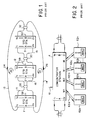
- a standard FDDI local area network includes first, second and third standard FDDI stations or connection nodes 1, 2 and 3.
- Each standard station includes first input and output ports 1i and 1o, respectively, and second input and output ports 2i and 2o, respectively.
- Input-output port 1i, 2o is also known as an A port
- input-output port 2i, 1o is also known as a B port.
- the first output ports 1o of each of the three standard stations 1, 2 and 3 are connected by fiber-optic transmission paths to the first input port 1i of the next standard station.
- a transmission path 11 connects from output port 1o of station 1 to input port 1i of station 2.
- a transmission path 12 connects from output port 1o of station 2 to input port 1i of station 3, and a transmission path 13 connects from output port 1o of station 3 to input port 1i of station 1, thereby forming a first loop, designated generally as 20, by which data can flow in the direction of arrow 24 among stations 1, 2 and 3.
- the second output ports 2o of each of the three standard stations 1, 2 and 3 are connected by fiber-optic transmission paths to the second input port 2i of the next standard station.
- a transmission path 14 connects from output port 2o of station 1 to input port 2i of station 3.
- a transmission path 15 connects from output port 2o of station 3 to input port 2i of station 2
- a transmission path 16 connects from output port 1o of station 2 to input port 2i of station 1, thereby forming a second loop designated generally as 22 by which data can flow in the direction of arrow 26 among stations 1, 2 and 3.
- a transmission path is a path by which signal travels essentially unchanged from one location to another.
- a path may include cable, connectors, repeaters, switches, attenuators, and the like, the presence of which does not affect the signal.
- Each station includes a Media Access Control unit which is associated with one, but not both, input-output ports, so that one of the two loops is designated as the main or primary loop.
- FIGURE 1 The system as illustrated in FIGURE 1 includes only three stations for simplicity of explanation, but could include a large number of such stations, connected in a similar manner.
- each station is connected to the next station by means of two fiber-optic transmission paths, as for example station 1 is connected to station 2 by transmission paths 11 and 16, in which data flows in mutually opposite directions.
- An envelope designated 28 represents the practical fact that the two fiber optic transmission paths 11 and 16 are often combined into a single multifiber cable.
- envelopes 30 and 32 represent the combining of fibers 12 and 15 into a cable 30, and the combining of fibers 13 and 14 into cable 32.
- the FDDI network as so far described in conjunction with FIGURE 1 is used by connecting sensors, computers (and their associated operator inputs) or controlled device& to externally accessibie data paths associated with each station, such as path 58 associated with station 1, and paths 59 and 60 associated with stations 2 and 3, respectively.
- a token is produced at the primary output port of a station when it has transmitted all its current information, and the next station on the primary loop either seizes the token to make time available for its own transmission, or retransmits the token on the primary loop or ring to the next station when it has no data to transmit.
- the ability to transmit unimpeded on the common bus steps from station to station with the token. Reception is not dependent on the token, and all stations may, essentially simultaneously, receive data which is relevant to the stations.
- Concentrators are allowed within the FDDI standard for expanded system connectivity. As described in an article entitled “Using Redundancy In FDDI Networks", by Ocheltree, published at pages 261-267 of the proceedings of the 15 th Conference on Local Computer Networks, Minneapolis, Minn. September 30- October 3, 1990, and in an article entitled “The DECconcentrator 500 Product”, by Tiffany et al., published at pp 64-75 of the Spring, 1991 issue of Digital Technical Journal, concentrators include a plurality of master ports in addition to the A and B ports.
- FIGURE 2 illustrates a concentrator station in accordance with FDDI standards.
- an FDDI concentrator station 4 includes an A port with 1i and 1o ports, a B port including 2i and 2o ports, and a path 61 for connection to a local sensor or other device, just as in the standard FDDI stations of FIGURE 1.
- concentrator station 4 of FIGURE 3 includes a plurality of "master" (M) ports, which are available for connection of additional single stations 62a, 62b, 62c,..62n.
- M master
- each floor might have a concentrator station, with the A and B ports connected with other concentrators on other floors in a loop as described in conjunction with FIGURE 1, and at each floor, the M ports of the concentrator for that floor are connected by individual two-fiber cables to each separate single station.
- concentrator 4 of FIGURE 2 were on the fourth floor of such a building, port M1 would be connected to fourth-floor equipment station 62a by way of a cable 63a, port M2 would be connected to fourth-floor equipment station 62b by way of a cable 63b, etc.
- the A and B ports of the concentrator would, of course, be connected to other stations on the third and fifth floors.
- the additional single stations 62 of FIGURE 4 are part of a "tree", which in the case of single stations as in FIGURE 4 cannot be expanded to further levels. If, in FIGURE 4, each single station 62 were to be replaced by a concentrator station which was connected to its higher-level concentrator station (station 4 in FIGURE 1) at one of its A or B ports, additional stations at a third level could be connected to the various M ports of the second-level station, to thereby create a tree with many levels. In such an arrangement, the lower-level stations all couple back to loop through concentrator 4, and are termed "singly homed".
- each low-level station can couple to the loop through two (or possibly more) paths, and they are said to be "dual homed", all as described, for example, in the abovementioned Ocheltree article.
- the token is received at the 1i port as in FIGURE 1, and is routed in succession to each of the active M ports and to the stations connected thereto, i.e. from port B to port M1, then down through all the stations in the M1 path, then to M2, and through all the stations in the M2 string,...
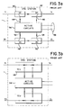
- FIGURE 3a illustrates one possible configuration of bus connections within a standard or concentrator station, taken as standard station 1 for definiteness.
- first and second directional couplers 40 and 42 respectively, have their main through lines coupled to each other and to input port 1i and output port 1o.
- the branch lines 44 and 46 of directional couplers 40 and 42, respectively, are coupled to active circuits illustrated as a block 56, which may include light detectors and modulators.
- third and fourth directional couplers 50 and 48 have their through paths coupled to each other and to input and output ports 2i and 2o, respectively, and their coupled branch lines coupled to active circuit block 56.
- Suitable directional couplers include the well-known star couplers.
- this arrangement couples signals directly from input port 1i to output port 1o, and from input port 2i directly to output port 2o, and also couples the active circuit portion 56 to receive signals from the input ports 1i and 2i of standard station 1, and to couple signals therefrom to output ports 1o and 2o of station 1, but has the disadvantage of splitting the transmission power and thereby reducing the signal-to-noise ratio. In many applications, this will be of no consequence, but when large numbers of stations are to be interconnected, the cumulative loss of the couplers may exceed the regenerative power of the various stations.
- FIGURE 3b Lower through loss at each station is permitted by the use of a switched "Trunk Coupling Unit” (TCU), illustrated in FIGURE 3b.
- TCU Trusted Coupling Unit
- station 1 receives signal through input port 1i, which is applied to a moving-mirror fiber-optic switch 98.
- Switch 98 allows signal to be routed directly from input port 1i to output port 1o when that station or node is shut down or deprived of power, which is a fail-safe bypass mode of operation. In normal operation, when the station is powered up, switch 98 couples signal from input port 1i to the active portions 56 of the node, and from the active portion to output port 1o.
- the operation of the TCU associated with ports 2i and 2o is similar.
- FIGURE 4a is similar to FIGURE 1, but includes an assumed break in a transmission line. While standard stations are described, the following discussion is equally applicable to concentrator stations. As mentioned, the transmission lines are actually coupled into cables including at least two paths, as for example cable 28 includes the two transmission paths 11 and 16 extending between stations 1 and 2. As a result, a break in one cable almost invariably breaks both optical fibers therein.
- the FDDI standard takes cognizance of this likelihood, and arranges its error detection circuits within each station to recognize the existence of faults, which include (a) a fault in the transmission path terminating at a 1i input port, and (b) a fault in the transmission path which starts at a 1o output port.
- the (a) type of fault may be termed an "upstream” fault, and the (b) fault may be termed “downstream", relative to the "main” data path or loop.
- a large "X" is placed over multifiber cable 28, thereby indicating that it is broken, possibly as a result of environmental or hostile action.
- the break is a downstream "b"fault, and as to station 2, it is an "a" type upstream fault.
- the FDDI standard requires the station subject to an upstream fault (in this example, station 2) to disconnect its 2i input from its 2o output and reconnect or "wrap" it to its 1o output, as illustrated by dashed path 70 in station 2.
- the disconnection of input port 2i from output port 2o is of no consequence, because any data applied to output port 2o cannot traverse data path 16 of cable 28 anyway.
- the FDDI standard also prescribes that a station subject to a downstream fault (station 1 in the example) must disconnect its 1i input port from the 1o output port, and reconnect or wrap it to the 2o output port, as illustrated by dash line 72 in station 1.
- the FDDI wrap protocol results in formation of a third loop to replace the broken first loop 20 and second loop 22.
- the third loop extends from output port 1o of station 2, through path 12, ports 1i and 1o of station 3 to path 13, then through input port 1i, path 72, and output port 2o of station 1, through path 14 to input port 2i of station 3, and out of output port 2o of station 3, through data path 15 to input port 2i of station 2, and finally through path 70 back to output port 1o of station 2.
- a single break has no significant effect on the communications among stations 1, 2 and 3 (although the delay may increase somewhat).
- FIGURE 4b is similar to FIGURE 4a, differing only in that a second break in the cabling is shown, illustrated by a large "X" over cable 30. This break obviously isolates station 2 from stations 1 and 3.
- Station 1 still experiences a downstream fault, and responds by producing internal reconfiguration path 72.
- Station 3 experiences an upstream fault, and responds by reconfiguring itself by wrapping its 2i input port to its 1o output port, just as station 2 did in FIGURE 4a.
- the wrap path in station 3 is designated 74.
- station 2 is further isolated by the operation of the wrap specified by the FDDI protocol, which requires disconnection of paths 11 and 15 from station 2.
- the illustrated system includes only three stations, for simplicity of explanation. It should be understood that station 2 of FIGURE 4b may actually represent a plurality of stations, and that the wrap specification will result in those additional stations forming their own interconnected loop, which, however, is totally isolated (by the multiple breaks) from the loop including stations 1 and 3. For mission-critical data communications, isolation of whole sections by damage to two unrelated data paths may not be acceptable.
- looping data paths in an FDDI system are often illustrated side-by-side, as is shown by the alternate placement of data path 14 in the form of a dot-dash line 14b adjacent to data path 14 in FIGURE 4b.
- This configuration results in the use of the terminology of formation of a "U” or “horseshoe” path instead of an alternative "loop” path when a wrap occurs.
- reconfiguration forms a horseshoe or a loop, depending upon the form or topology of the circuit which one has in mind, but the horseehoe and the loop are equivalent terms in this context.
- a SAFENET study group established by the Navy has conducted a review of LAN for mission-critical applications, and is in the process of generating SAFENET I standards based on IEEE 802.5 "free-token" protocol, which standard specifies that the two fiber transmission lines be separately routed, and adopts "ring hop", which amounts to abandoning a defective loop or ring and using the operational loop.
- the free-token protocol is not considered advantageous, because the hold time at any station is not controlled, and thus priority messages may be delayed excessively.
- the SAFENET group has also at least partially generated SAFENET II LAN standards.
- the SAFENET II standards define a timed token ring pursuant to FDDI standards, but in which the dual counter-rotating rings are separately routed. It supports a single failure, but degrades in the presence of additional failures, and therefore is no better than FDDI.
- a LAN according to the invention uses FDDI standards, but interconnects the FDDI standard concentrator stations elements in a manner which, together with intraconnection protocols associated with each concentrator station which are in conformance with the FDDI standards, provide redundancy and reliability tending to equal that of the point-to-point system.
- This is accomplished, in short, by using, primary (or first) and alternate (or second) loops or data buses, each including first and second transmission paths operating in mutually opposite directions, with concentrator stations instead of FDDI standard stations.
- Each concentrator station includes arrangements which sense a break in that portion of the primary loop terminating at the station, and which, in that station, couples input and output ports originally coupled to the broken cable to an alternate cable segment.
- a communication system 500 includes a plurality of concentrator stations 501, 502, 503, and 504 are coupled with a loop.
- the A and B ports of adjacent stations are not directly connected together, but instead each A or B port is connected to an M port of the adjacent station.
- the M1 output (o) port of station 504 is connected by a path 513 to the B input (i) port of station 503.
- the M1 o port of station 503 is connected by path 512 to the B i port of station 502, and the M1 o port of station 502 is connected by path 511 to the B i port of station 501.
- the use of concentrator stations may result in a net increase in token transit time by comparison with standard stations, but the increased transit time is considered minor by comparison with the advantages of the system, as described below.
- M ports may be available in each concentrator station, and those additional M ports may be used to access additional tree-connected stations, if desired.
- FIGURE 5 The various data paths of FIGURE 5 are grouped into cables, as suggested by the encompassing circles. Each cable is referred to by the same number as that of the lower- numbered one of the associated data path which it contains.
- a primary loop is designated by a media access control unit in the stations, and includes FDDI standard B and M ports (the M ports are designated with numerals for convenience).
- the token passes from the B port to the first active M port, which in this case is the M1 port.
- the progression from a B port to an M1 port results in a further connection to a B port, which corresponds to progress around the primary loop.
- End stations 501 and 504 wrap according to the FDDI standard, with station 501 wrapping the B i port to the B o port. Also, station 504 wraps the M1 i port to the M1 o port.
- This wrapping forms the closed primary loop.
- the closed loop so formed in the root topology by the wrapping includes paths 511, 512, 513, 514, 515, and 516.
- the other paths in accordance with FDDI concentrator specifications, are in continuous self-testing of the individual inter-station data paths.
- the stations test data paths 521 and 526, which may be conceived of as a small loop, and also test data path pairs 522, 515; and 523, 524.
- alternate cables 521, 522 and 523 while they are connected in the same manner as the cables 511, 512, and 513, may be considered not to form a loop, because the individual segments are undergoing individual testing when not being used for carrying data.
- each station switches from a particular failed segment of the primary loop to the associated alternate segment. For example, if an "upstream" break occurs in cable 511 of FIGURE 5, as suggested by the letter x, or in either of the data paths 511 or 516 contained therein, which are part of the primary loop, station 501 routes data, which it would otherwise have applied to its B o port, to its A o port instead, so that the data can proceed over data path 521 to the M2 i port of station 502. Station 502, according to FDDI standards, would ordinarily route data entering its B port to the first active M port, which is M1.
- station 502 In the presence of a "downstream" fault relative to port M1, station 502, pursuant to the FDDI standard, routes data incoming to its B i port to its M2 o port instead of to the M1 port, so that it may be transmitted over data path 526 to station 501.
- Station 502 also in accordance with FDDI standards, routes data incoming to its M1 i port to its B o port.
- a break on cable 511, downstream from station 502 results in that station rerouting its B inputs and outputs to its M2 inputs and outputs, thereby maintaining communication with station 501 by way of unbroken cable 521.
- the FDDI reconfiguration when used in a system structured as described, switches data from a segment of the primary loop to an alternate segment.
- the system as described switches the data flow to the corresponding alternate segment. For example, if an additional break occurs in the system of FIGURE 1, as for example at the "x" in cable 513, the system switches over to alternate cable 523. It should be noted that a break in an alternate path while the primary path is operational-will not cause any alteration in system operation, it merely results in loss of an alternative for the particular primary path for which it is the alternate.
- the loop arrangement 500 of FIGURE 5 includes a station 501 which includes M1 and M2 ports, which can be connected to the A and B ports of additional concentrator stations to extend the loop.
- each concentrator station can include additional M port pairs, which might be designated M3 and M4, for example, another kind of connection can be made.
- FIGURE 6 illustrates a portion of the arrangement of FIGURE 5, including stations 502, 503, and 504, and also illustrating additional M ports M3 and M4. As illustrated in FIGURE 6, the M3 port of station 503 is connected to the B port of an additional concentrator station 506, and the M4 port of station 503 is connected to the A port of station 506.
- a token originating at station 504 of FIGURE 6 enters the B port of station 503, and enters the active or primary one of the M3, M4 port pair of station 506, which in normal operation will be the B port.
- the token will proceed to the M1 output port of station 506, and through any stations downstream therefrom, finally returning to station 503, and becoming available for transmission to station 502 and stations, such as 501, which are downstream therefrom.
- the right-most concentrator 504 includes unused A and B ports.
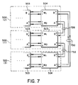
- communication system 500 of FIGURE 5 is similar to an unused standard FDDI station, such as any one of the stations of FIGURE 1 by itself. Consequently, a plurality of the communications systems 500 of FIGURE 5 can be interconnected in the manner illustrated in FIGURE 1. More particularly, a plurality of systems 500 can be arrayed in a "pitchfork" configuration, such as that illustrated in FIGURE 7.
- elements corresponding to those of FIGURE 5 are designated by like reference numerals.
- the bottom-most system 500 corresponds in principle to station 3 of FIGURE 1, and it therefore carries the additional parenthetical designation (3).
- the B port of system (3) of FIGURE 7 is connected by a two-conductor or two-path cable designated 832 (corresponding to cable 32 of FIGURE 1) to the A port of the right-most station 504 of system 500 (1), which corresponds in principle to station 1 of FIGURE 1.
- the B port of station 504 of system 500 (1) is connected over a cable 728, corresponding to cable 28 of FIGURE 1, to the A port of station 504 of system 500 (2) of FIGURE 7.
- the B port of station 504 of system 500 (2) of FIGURE 7 is connected by a cable 730, corresponding to cable 30 of FIGURE 1, to the A port of station 504 of system 500 (3) of FIGURE 7.
- the concentrator structure according to the invention can be connected into supraloops pursuant to the FDDI standard. Unfortunately, the supraloops formed in this fashion do not enjoy the same survivability in the presence of multiple breaks as that of the systems according to the invention.
- FIGURE 8 is similar to Figure 5, and corresponding elements are similarly numbered.
- FIGURE 8 differs from FIGURE 5 in that additional cables 818, 828 (defining the cable by the lowest transmission path or fiber designator) are connected from the M1 port of station 501 to the B port of station 504, and from the M2 port of station 501 to the A port of station 504. These cables, together with the other structure of FIGURE 8, forms loops.
- the data or token enters the B i port of station 504, and proceeds to its M1 o port, and through path 513 to the B i port of station 503.
- the data proceeds through station 503 to its M1 o port, through path 512 to the B i port of station 502 and thence to its M1 o port.
- the data proceeds through data path 511 and the B i port of station 501, and through the M1 o port of station 501 and back onto path 820. It is believed that this configuration may fail to recognize the fact that the M1 port of station 501 is connected to the B port of station 504, and that under normal conditions of unbroken paths, that the station will not use the additional path provided by cable 818.
- the system may then recognize the presence of cable 818, and retain a fully operational primary path, without recourse to the alternate paths. This would advantageously provide another level of redundancy or reconfiguration. Similar comments apply to the presence of additional cable 828 of FIGURE 8 in the alternate paths.
- the LAN according to the invention may be used in vehicles for adverse environments, as for example commercial and military aircraft and spacecraft, ships and submarines, land vehicles such as trains and buses, military land vehicles such as tanks and APCs, and in fixed stations where operability in the presence of damage is important, as in power stations, nuclear plants, radar and other defense systems, airport and air traffic control systems, and the like, and also other systems where outages are important, such as medical and financial systems.
Landscapes
- Engineering & Computer Science (AREA)
- Computer Networks & Wireless Communication (AREA)
- Signal Processing (AREA)
- Small-Scale Networks (AREA)
- Hardware Redundancy (AREA)
Applications Claiming Priority (2)
| Application Number | Priority Date | Filing Date | Title |
|---|---|---|---|
| US07/829,782 US5317569A (en) | 1992-01-31 | 1992-01-31 | Alternate path FDDI standard LAN |
| US829782 | 1997-03-31 |
Publications (2)
| Publication Number | Publication Date |
|---|---|
| EP0559314A2 true EP0559314A2 (fr) | 1993-09-08 |
| EP0559314A3 EP0559314A3 (en) | 1994-06-15 |
Family
ID=25255544
Family Applications (1)
| Application Number | Title | Priority Date | Filing Date |
|---|---|---|---|
| EP19930300333 Withdrawn EP0559314A3 (en) | 1992-01-31 | 1993-01-19 | Alternate path fddi standard lan |
Country Status (3)
| Country | Link |
|---|---|
| US (1) | US5317569A (fr) |
| EP (1) | EP0559314A3 (fr) |
| JP (1) | JPH05347631A (fr) |
Cited By (3)
| Publication number | Priority date | Publication date | Assignee | Title |
|---|---|---|---|---|
| WO1998045983A3 (fr) * | 1997-04-10 | 1999-03-11 | Bosch Gmbh Robert | Liaison de communication de donnees dans un reseau de communication hierarchique a bus, fonctionnant selon un protocole demande/reponse, a savoir selon le 'protocole d'appel selectif' |
| DE102004041820A1 (de) * | 2004-08-27 | 2006-03-09 | Siemens Ag | Schiff mit einem Datennetzwerk |
| WO2005053223A3 (fr) * | 2003-11-19 | 2007-04-19 | Honeywell Int Inc | Unite d'interface anneau |
Families Citing this family (13)
| Publication number | Priority date | Publication date | Assignee | Title |
|---|---|---|---|---|
| US5546378A (en) * | 1994-07-21 | 1996-08-13 | Newbridge Networks Corporation | Fault tolerant FDDI wiring hub |
| US6275468B1 (en) * | 1996-07-31 | 2001-08-14 | Motorola, Inc. | Automatic timing adjustment for diverse routing of HFC systems |
| US6587974B1 (en) * | 1999-11-19 | 2003-07-01 | Tyco Telecommunications (Us) Inc. | Method for fault detection and fast protection switching in transmission systems |
| US7200108B2 (en) * | 2001-06-29 | 2007-04-03 | International Business Machines Corporation | Method and apparatus for recovery from faults in a loop network |
| US6766482B1 (en) | 2001-10-31 | 2004-07-20 | Extreme Networks | Ethernet automatic protection switching |
| DE10255687B4 (de) * | 2002-11-28 | 2011-08-11 | Lantiq Deutschland GmbH, 85579 | Verfahren zur Verringerung des Crestfaktors eines Multiträgersignals |
| US20040177203A1 (en) * | 2003-01-27 | 2004-09-09 | International Business Machines Corporation | Dual time sliced circular bus |
| US7254663B2 (en) * | 2004-07-22 | 2007-08-07 | International Business Machines Corporation | Multi-node architecture with daisy chain communication link configurable to operate in unidirectional and bidirectional modes |
| US7334070B2 (en) * | 2004-10-29 | 2008-02-19 | International Business Machines Corporation | Multi-channel memory architecture for daisy chained arrangements of nodes with bridging between memory channels |
| JP2006195821A (ja) * | 2005-01-14 | 2006-07-27 | Fujitsu Ltd | 情報処理システムの制御方法、情報処理システム、ダイレクトメモリアクセス制御装置、プログラム |
| DE102005030073A1 (de) * | 2005-06-27 | 2006-12-28 | Airbus Deutschland Gmbh | Fehlertolerantes Datenübertragungssystem in einem Passagierflugzeug |
| GB0612482D0 (en) * | 2006-06-23 | 2006-08-02 | Ibm | Apparatus and method for controlling raid array rebuild |
| JP5095350B2 (ja) * | 2007-06-11 | 2012-12-12 | ナブテスコ株式会社 | 舶用制御装置及びその表示器 |
Family Cites Families (3)
| Publication number | Priority date | Publication date | Assignee | Title |
|---|---|---|---|---|
| DE3427891A1 (de) * | 1984-07-28 | 1986-01-30 | Philips Patentverwaltung Gmbh, 2000 Hamburg | Anordnung zur informationsuebertragung mit rekonfiguration |
| EP0271626B1 (fr) * | 1986-12-16 | 1992-03-04 | International Business Machines Corporation | Mécanisme de contournement pour des unités connectées en "daisy chain" |
| US5105420A (en) * | 1990-04-09 | 1992-04-14 | At&T Bell Laboratories | Method and apparatus for reconfiguring interconnections between switching system functional units |
-
1992
- 1992-01-31 US US07/829,782 patent/US5317569A/en not_active Expired - Lifetime
-
1993
- 1993-01-19 EP EP19930300333 patent/EP0559314A3/en not_active Withdrawn
- 1993-01-26 JP JP5010358A patent/JPH05347631A/ja not_active Withdrawn
Non-Patent Citations (6)
| Title |
|---|
| 15TH CONFERENCE ON LOCAL COMPUTER NETWORKS September 1990 , US pages 261 - 267 K.B. OCHELTREE 'Using redundancy in FDDI Networks' * |
| COMPUTER NETWORKS AND ISDN SYSTEMS vol. 23, no. 1/3 , November 1991 , AMSTERDAM NL pages 51 - 55 FRANZEN M. ET AL. 'FDDI concentrators and how they work together with other FDDI network components' * |
| DIGITAL TECHNICAL JOURNAL vol. 3, no. 2 , 1991 , US pages 64 - 75 W.J. TIFFANY 'The DECconcentrator 500 Product' * |
| INFOCOM '89 vol. 3 , April 1989 , NEW YORK, US pages 989 - 997 S. NAKAYASHIKI ET AL. 'Wraping and Merging Reconfiguration Mechanisms of a Conter-Rotating Dual Ring' * |
| INTERNATIONAL CONFERENCE ON COMMUNICATIONS vol. 3 , June 1991 , NEW YORK, US pages 1418 - 1424 S.H. HERSEY 'ARCHITECTURES AND APPLICATIONS OF SONET IN A SELF-HEALING NETWORK' * |
| INTERNATIONAL TELECOMMUNICATIONS SYMPOSIUM September 1990 , NEW YORK, US pages 255 - 259 RUIZ A. ET AL. 'An Architecture and Implementation for an FDDI MAC Concentrator' * |
Cited By (4)
| Publication number | Priority date | Publication date | Assignee | Title |
|---|---|---|---|---|
| WO1998045983A3 (fr) * | 1997-04-10 | 1999-03-11 | Bosch Gmbh Robert | Liaison de communication de donnees dans un reseau de communication hierarchique a bus, fonctionnant selon un protocole demande/reponse, a savoir selon le 'protocole d'appel selectif' |
| WO2005053223A3 (fr) * | 2003-11-19 | 2007-04-19 | Honeywell Int Inc | Unite d'interface anneau |
| DE102004041820A1 (de) * | 2004-08-27 | 2006-03-09 | Siemens Ag | Schiff mit einem Datennetzwerk |
| US7945157B2 (en) | 2004-08-27 | 2011-05-17 | Siemens Aktiengesellschaft | Ship with a data network |
Also Published As
| Publication number | Publication date |
|---|---|
| US5317569A (en) | 1994-05-31 |
| EP0559314A3 (en) | 1994-06-15 |
| JPH05347631A (ja) | 1993-12-27 |
Similar Documents
| Publication | Publication Date | Title |
|---|---|---|
| US5317569A (en) | Alternate path FDDI standard LAN | |
| JP2826907B2 (ja) | 信号保護及び監視システム | |
| EP1811723B1 (fr) | Réseau auto-expansible à recuit automatique | |
| US4596982A (en) | Reconfigurable ring communications network | |
| EP0468813B1 (fr) | Système ATM de communication à anneau double | |
| US6233704B1 (en) | System and method for fault-tolerant transmission of data within a dual ring network | |
| US6052210A (en) | System and method for increasing the robustness of an optical ring network | |
| US4538264A (en) | Self-repairing ring communications network | |
| JP3574425B2 (ja) | 耐多重障害ネットワーク構造を利用したパケット処理方法 | |
| CN108259265B (zh) | 一种军用1394b总线网络信道完整性检测方法 | |
| CA2302257C (fr) | Dispositif de communication pour la transmission de signaux d'information | |
| US6041036A (en) | Dual receive, dual transmit fault tolerant network arrangement and packet handling method | |
| US5060224A (en) | Method and apparatus for connecting branch networks with a trunk network in optical transmission system | |
| US5594581A (en) | Low loss optical transmission/monitoring path selection in redundant equipment terminals | |
| JP3006670B2 (ja) | 光海底分岐装置およびその伝送路切替方法 | |
| US7164684B2 (en) | Ethernet node having hub, switch and/or repeater characteristics | |
| US5513369A (en) | Star coupler device including means for connecting multiple star couplers together in a cascaded relationship | |
| US4973955A (en) | Data transmission system | |
| JPS6367846A (ja) | 船舶内ロ−カルエリアネツトワ−クシステム | |
| EP1267588A2 (fr) | Localisation des pannes dans des commutateurs photonique à plusieurs étages | |
| US20030223380A1 (en) | Ring network system | |
| US11032101B2 (en) | Vehicle having fail-safe internal data transfer | |
| JP2853750B2 (ja) | 現用予備切替え伝送システム | |
| Hiles et al. | Experimentation on the concentrator tree with loopback | |
| CN117200856A (zh) | 面向载人运载火箭的2-3模复合冗余tte通信网络拓扑结构 |
Legal Events
| Date | Code | Title | Description |
|---|---|---|---|
| PUAI | Public reference made under article 153(3) epc to a published international application that has entered the european phase |
Free format text: ORIGINAL CODE: 0009012 |
|
| AK | Designated contracting states |
Kind code of ref document: A2 Designated state(s): DE FR GB |
|
| PUAL | Search report despatched |
Free format text: ORIGINAL CODE: 0009013 |
|
| AK | Designated contracting states |
Kind code of ref document: A3 Designated state(s): DE FR GB |
|
| 17P | Request for examination filed |
Effective date: 19941215 |
|
| 17Q | First examination report despatched |
Effective date: 19970909 |
|
| 18D | Application deemed to be withdrawn |
Effective date: 19980120 |