EP0559564A1 - Progressives Expansionsventil - Google Patents
Progressives Expansionsventil Download PDFInfo
- Publication number
- EP0559564A1 EP0559564A1 EP93400557A EP93400557A EP0559564A1 EP 0559564 A1 EP0559564 A1 EP 0559564A1 EP 93400557 A EP93400557 A EP 93400557A EP 93400557 A EP93400557 A EP 93400557A EP 0559564 A1 EP0559564 A1 EP 0559564A1
- Authority
- EP
- European Patent Office
- Prior art keywords
- fluid
- valve
- seat
- zones
- sleeve
- Prior art date
- Legal status (The legal status is an assumption and is not a legal conclusion. Google has not performed a legal analysis and makes no representation as to the accuracy of the status listed.)
- Withdrawn
Links
- 230000000750 progressive effect Effects 0.000 title 1
- 239000012530 fluid Substances 0.000 claims abstract description 36
- 125000006850 spacer group Chemical group 0.000 claims description 4
- 238000011144 upstream manufacturing Methods 0.000 description 9
- 238000009834 vaporization Methods 0.000 description 7
- 230000008016 vaporization Effects 0.000 description 6
- 239000007788 liquid Substances 0.000 description 3
- 239000002245 particle Substances 0.000 description 3
- 241000928106 Alain Species 0.000 description 1
- 238000009825 accumulation Methods 0.000 description 1
- 230000001143 conditioned effect Effects 0.000 description 1
- 238000006073 displacement reaction Methods 0.000 description 1
- 238000011010 flushing procedure Methods 0.000 description 1
- 238000010926 purge Methods 0.000 description 1
- 238000007789 sealing Methods 0.000 description 1
Images

Classifications
-
- F—MECHANICAL ENGINEERING; LIGHTING; HEATING; WEAPONS; BLASTING
- F16—ENGINEERING ELEMENTS AND UNITS; GENERAL MEASURES FOR PRODUCING AND MAINTAINING EFFECTIVE FUNCTIONING OF MACHINES OR INSTALLATIONS; THERMAL INSULATION IN GENERAL
- F16K—VALVES; TAPS; COCKS; ACTUATING-FLOATS; DEVICES FOR VENTING OR AERATING
- F16K47/00—Means in valves for absorbing fluid energy
- F16K47/08—Means in valves for absorbing fluid energy for decreasing pressure or noise level and having a throttling member separate from the closure member, e.g. screens, slots, labyrinths
-
- F—MECHANICAL ENGINEERING; LIGHTING; HEATING; WEAPONS; BLASTING
- F25—REFRIGERATION OR COOLING; COMBINED HEATING AND REFRIGERATION SYSTEMS; HEAT PUMP SYSTEMS; MANUFACTURE OR STORAGE OF ICE; LIQUEFACTION SOLIDIFICATION OF GASES
- F25B—REFRIGERATION MACHINES, PLANTS OR SYSTEMS; COMBINED HEATING AND REFRIGERATION SYSTEMS; HEAT PUMP SYSTEMS
- F25B41/00—Fluid-circulation arrangements
- F25B41/30—Expansion means; Dispositions thereof
- F25B41/31—Expansion valves
Definitions
- the present invention relates to valves and in particular to valves intended to put in communication or interrupt this communication between a part of a fluid circuit at relatively high pressure and a part of this circuit in which the pressure is substantially less.
- French patent No. 78 21 693 filed on July 21, 1978, in the name of Alain VERDELET, describes a valve for a fluid circuit comprising a body, an inlet pipe and an outlet pipe, a seat delimiting an orifice for the passage of the fluid, a shutter cooperating with the seat, as well as, coaxially with the seat, a series of passages whose section increases in the direction of the flow of the fluid and which alternate with cavities constituting expansion chambers of the fluid, these passages being delimited by an axial rod and annular disks approximately concentric with this rod and which are part of separate elements in the form of cups, stacked in a cylindrical wall housing formed in the body and delimiting between them the chambers of detent, the orifices formed in the discs having, as known per se, a constant section and being traversed by a portion, of frustoconical shape, of the axial rod.
- valve of the type defined above makes it possible to ensure successive expansion by adjusting the value of the fluid pressure by the flow coefficient determined by the section of the corresponding passage defined by an annular disc and the axial zone of the frustoconical portion. of the axial rod located opposite the orifice formed in the disc.
- the invention aims to improve the valve defined above, in particular with a view to preventing vaporization phenomena.
- the zones of different conicities alternate with cylindrical zones of reduced section.
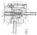
- Fig.1 shows in section an improved valve according to the invention.
- a valve comprising a body 1 made in two parts 2,3 connected for example by screws 4.
- Part 2 of the body comprises a fluid inlet conduit 5 connected to a high pressure circuit and a fluid outlet conduit 6 connected to a circuit which can, for example constitute a circuit for withdrawing the fluid contained in the high pressure circuit.
- the two elements 2 and 3 which constitute the body 1 are drilled axially at 7 and 8.
- a sleeve 9 which is held axially between the bottom of the housing 5 formed in the part 2 of the body 1 and a shoulder end portion 10 of the part 3 of the body 1.
- the sleeve 9 has an axial bore 11 aligned with the fluid inlet duct 5 which is connected to an axial passage 12 formed in the part 2 of the body 1.
- a liner consisting of an alternation of annular discs 13 and spacer sleeves 14 which together define successive expansion chambers 15 disposed on the path of the fluid.
- a ring 16 of greater thickness which forms a seat for a shutter 17 axially displaceable in the body 1 and extended by a rod 18 comprising successive frustoconical zones 19 interposed with cylindrical zones 20 of smaller diameter which cooperate with the orifices provided in the annular discs 13 to define passages or intervals of variable sections alternating with the expansion chambers 15.
- annular disc 16 constituting the seat for the obturator 17
- a spacer sleeve 14 pierced with radial orifices 21.
- the assembly of the lining constituted by the annular discs 13 and the spacer sockets 14 is held in place against a shoulder rim 22 of the sleeve 9 by an externally threaded ring 23 engaged in a threaded part of the end of the axial bore 11 of the sleeve 9.
- this chamber 25 opens a radial orifice 26 formed in the side wall of the part 2 of the body 1 and connected to the fluid outlet conduit 6.
- the shutter 17 is fixed to an operating rod 28 mounted axially displaceable in the axial bore 8 of the part 3 of the body 1 with the interposition of conventional sealing means which are not described here.
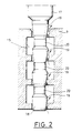
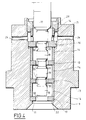
- the rod 18 which extends the shutter 17 comprises four zones of different conicities which define, with the annular discs 13 of the liner shown in FIGS. 1, 3 and 4, three expansion chambers 15.
- Fig.3 there is shown the valve according to the invention in the closed position in which it is seen that the various frustoconical zones 19 are arranged opposite the annular discs 13 and 16 corresponding and the shutter 17 is applied to its defined seat by the upper ring 16 of the sleeve liner 9.
- the vaporization pressure is a characteristic of the liquid which remains unchanged, it is necessary to act on the upstream pressure or on the coefficient Kc of the valve.
- the arrangement according to the invention further comprises, as shown in the drawings, cylindrical zones 20 of reduced sections which, when they are presented opposite the orifices defined in the annular discs 13, 16 of the sleeve liner 9, during displacement axial of the shutter 17 and of the rod 18 towards the top of Fig. 1 to 4 offer a very large flow section which can cause a flushing phenomenon.
- the zones of smaller sections 20 are arranged opposite the axial orifices provided in the annular discs 13 and 16, so that the fluid is free to circulate between the upstream and downstream of the valve, the significant intervals delimited by the cylindrical zones 20 and the walls of the internal passages of annular discs 13 and 16, allowing the fluid which then circulates in the valve, to carry with it any particles which may have accumulated during valve operation with controlled expansion of the fluid.
- a valve such as that which has just been described with reference to the drawings, can be actuated by a servomotor which can in turn be connected to sensors and to positioning devices not shown, thus making it possible to automate the assembly of valve.
- the valve according to the invention can vary a flow rate, a pressure and also ensure a constant flow rate with a constant downstream pressure while having upstream variations at the same time as it makes it possible to carry out a purge during a stuffing of the an accumulation of particles.
Landscapes
- Engineering & Computer Science (AREA)
- General Engineering & Computer Science (AREA)
- Mechanical Engineering (AREA)
- Physics & Mathematics (AREA)
- Thermal Sciences (AREA)
- Details Of Valves (AREA)
Applications Claiming Priority (2)
| Application Number | Priority Date | Filing Date | Title |
|---|---|---|---|
| FR9202538A FR2688284B1 (fr) | 1992-03-03 | 1992-03-03 | Vanne a detente progressive perfectionnee. |
| FR9202538 | 1992-03-03 |
Publications (1)
| Publication Number | Publication Date |
|---|---|
| EP0559564A1 true EP0559564A1 (de) | 1993-09-08 |
Family
ID=9427303
Family Applications (1)
| Application Number | Title | Priority Date | Filing Date |
|---|---|---|---|
| EP93400557A Withdrawn EP0559564A1 (de) | 1992-03-03 | 1993-03-03 | Progressives Expansionsventil |
Country Status (2)
| Country | Link |
|---|---|
| EP (1) | EP0559564A1 (de) |
| FR (1) | FR2688284B1 (de) |
Cited By (4)
| Publication number | Priority date | Publication date | Assignee | Title |
|---|---|---|---|---|
| RU2206015C1 (ru) * | 2001-12-26 | 2003-06-10 | Андреев Александр Павлович | Запорно-дроссельный клапан и его корпус |
| EP1650482A1 (de) * | 2004-10-20 | 2006-04-26 | Behr America, Inc | Expansionsventil, insbesondere für eine Klimaanlage eines Kraftfahrzeugs |
| CN110159834A (zh) * | 2019-05-07 | 2019-08-23 | 宁波国联电器科技有限公司 | 可调式co2浓度补偿器 |
| CN113513862A (zh) * | 2021-04-01 | 2021-10-19 | 西安交通大学 | 一种串联节流阀 |
Citations (4)
| Publication number | Priority date | Publication date | Assignee | Title |
|---|---|---|---|---|
| DE1068965B (de) * | 1959-11-12 | |||
| DE1958844A1 (de) * | 1968-12-10 | 1970-07-23 | Magdeburger Armaturenwerke | Absperr-,Drossel- und Regelorgan mit grossem Regelbereich |
| FR2431646A1 (fr) * | 1978-07-21 | 1980-02-15 | Verdelet Alain | Vanne perfectionnee, notamment pour raccordement entre des circuits a haute et basse pressions |
| DE3144609A1 (de) * | 1981-11-10 | 1983-06-23 | C.H. Zikesch GmbH, 4100 Duisburg | "ventil" |
-
1992
- 1992-03-03 FR FR9202538A patent/FR2688284B1/fr not_active Expired - Lifetime
-
1993
- 1993-03-03 EP EP93400557A patent/EP0559564A1/de not_active Withdrawn
Patent Citations (4)
| Publication number | Priority date | Publication date | Assignee | Title |
|---|---|---|---|---|
| DE1068965B (de) * | 1959-11-12 | |||
| DE1958844A1 (de) * | 1968-12-10 | 1970-07-23 | Magdeburger Armaturenwerke | Absperr-,Drossel- und Regelorgan mit grossem Regelbereich |
| FR2431646A1 (fr) * | 1978-07-21 | 1980-02-15 | Verdelet Alain | Vanne perfectionnee, notamment pour raccordement entre des circuits a haute et basse pressions |
| DE3144609A1 (de) * | 1981-11-10 | 1983-06-23 | C.H. Zikesch GmbH, 4100 Duisburg | "ventil" |
Non-Patent Citations (2)
| Title |
|---|
| CONTROL ENGINEERING Août 1973, NEW YORK US pages 42 - 44 R.E SELF 'How to Justify Special Control Valves' * |
| REGELUNGS-TECHNISCHE PRAXIS vol. 20, no. 9, Septembre 1978, MUNCHEN DE pages 270 - 277 SCHMITT 'Entwicklung geräuscharmer Stellglieder für Gase und Dämpfe' * |
Cited By (5)
| Publication number | Priority date | Publication date | Assignee | Title |
|---|---|---|---|---|
| RU2206015C1 (ru) * | 2001-12-26 | 2003-06-10 | Андреев Александр Павлович | Запорно-дроссельный клапан и его корпус |
| EP1650482A1 (de) * | 2004-10-20 | 2006-04-26 | Behr America, Inc | Expansionsventil, insbesondere für eine Klimaanlage eines Kraftfahrzeugs |
| CN110159834A (zh) * | 2019-05-07 | 2019-08-23 | 宁波国联电器科技有限公司 | 可调式co2浓度补偿器 |
| CN110159834B (zh) * | 2019-05-07 | 2024-06-04 | 宁波国联电器科技有限公司 | 可调式co2浓度补偿器 |
| CN113513862A (zh) * | 2021-04-01 | 2021-10-19 | 西安交通大学 | 一种串联节流阀 |
Also Published As
| Publication number | Publication date |
|---|---|
| FR2688284B1 (fr) | 1995-05-12 |
| FR2688284A1 (fr) | 1993-09-10 |
Similar Documents
| Publication | Publication Date | Title |
|---|---|---|
| WO2011030063A1 (fr) | Dispositif de distribution de liquide | |
| EP1019627B1 (de) | Saugstrahlpumpe mit einer düse mit variabelem durchschnitt | |
| EP0617974A1 (de) | Implantierbare Drainage zur Behandlung von Hydrocephalus | |
| FR2507736A1 (fr) | Dispositif d'attenuation des bruits d'un fluide en ecoulement turbulent non symetrique par rapport a un axe | |
| FR2617963A1 (fr) | Procede et dispositif de repartition d'un volume primaire d'un fluide avantageusement un liquide, en un nombre determine de volumes secondaires presentant une relation predefinie entre eux, par l'emploi d'orifices d'evacuation repartis symetriquement dans une chambre de repartition elle-meme symetrique | |
| FR3032254A1 (de) | ||
| EP0258129A1 (de) | Thermostatische Mengenvorrichtungen, insbesondere für Wasserverteilung | |
| BE897189A (fr) | Valve a asservissement montee dans un train de tiges de forage, | |
| FR2468009A1 (fr) | Pompe et/ou moteur a engrenages | |
| FR2553879A1 (fr) | Debitmetre a venturi a faibles pertes d'energie | |
| FR2522780A1 (fr) | Dispositif de determination de grandeurs mesurees dans des tuyauteries | |
| FR2515841A1 (fr) | Dispositif de selection de pression maximale | |
| FR2606853A1 (fr) | Vanne de sas perfectionnee | |
| FR2688284A1 (fr) | Vanne a detente progressive perfectionnee. | |
| EP1372811B1 (de) | Zylindrisches element mit geneigten flügeln für filterelement und entsprechende filtervorrichtung | |
| EP1186802A1 (de) | Antriebsvorrichtung mit Hydraulikmotor und Zahnradgetriebe | |
| EP1265012B1 (de) | Entlüftungsventil für eine Wasserleitung | |
| FR2517791A1 (fr) | Perfectionnements apportes aux distributeurs hydrauliques | |
| EP0149931B1 (de) | Filter mit mehreren Aufnahmekammern für das Filtrat und für eine andere Flüssigkeit welche durch den Rückstand den Hauptfiltrierung gebildet ist | |
| FR2620785A1 (fr) | Organe de controle de l'ecoulement d'un fluide constituant au moins un clapet anti-retour | |
| FR2828547A3 (fr) | Soupape de securite a double fonction | |
| EP1307273B1 (de) | Filtergehäuse für mikrofiltration | |
| FR2508588A1 (fr) | Vanne-melangeuse ou repartitrice | |
| EP1946050B1 (de) | Zylindrische messkammer eines wassermessers | |
| FR2705574A1 (fr) | Valve de drainage implantable pour le traitement de l'hydrocéphalie. |
Legal Events
| Date | Code | Title | Description |
|---|---|---|---|
| PUAI | Public reference made under article 153(3) epc to a published international application that has entered the european phase |
Free format text: ORIGINAL CODE: 0009012 |
|
| AK | Designated contracting states |
Kind code of ref document: A1 Designated state(s): BE DE ES GB IT LU NL |
|
| 17P | Request for examination filed |
Effective date: 19931203 |
|
| 17Q | First examination report despatched |
Effective date: 19950207 |
|
| STAA | Information on the status of an ep patent application or granted ep patent |
Free format text: STATUS: THE APPLICATION HAS BEEN WITHDRAWN |
|
| 18W | Application withdrawn |
Withdrawal date: 19950921 |