EP0559628A1 - Procédé et dispositif pour le séchage du papier - Google Patents
Procédé et dispositif pour le séchage du papier Download PDFInfo
- Publication number
- EP0559628A1 EP0559628A1 EP93850038A EP93850038A EP0559628A1 EP 0559628 A1 EP0559628 A1 EP 0559628A1 EP 93850038 A EP93850038 A EP 93850038A EP 93850038 A EP93850038 A EP 93850038A EP 0559628 A1 EP0559628 A1 EP 0559628A1
- Authority
- EP
- European Patent Office
- Prior art keywords
- cylinder
- flow
- web
- drying
- mantle
- Prior art date
- Legal status (The legal status is an assumption and is not a legal conclusion. Google has not performed a legal analysis and makes no representation as to the accuracy of the status listed.)
- Granted
Links
- 238000001035 drying Methods 0.000 title claims abstract description 38
- 238000000034 method Methods 0.000 title claims abstract description 19
- XLYOFNOQVPJJNP-UHFFFAOYSA-N water Substances O XLYOFNOQVPJJNP-UHFFFAOYSA-N 0.000 claims abstract description 31
- 239000004744 fabric Substances 0.000 claims description 22
- 239000000498 cooling water Substances 0.000 claims description 5
- 238000002485 combustion reaction Methods 0.000 claims description 4
- 239000002826 coolant Substances 0.000 claims description 4
- 125000006850 spacer group Chemical group 0.000 claims description 3
- 238000004804 winding Methods 0.000 claims description 3
- 239000011248 coating agent Substances 0.000 claims description 2
- 238000000576 coating method Methods 0.000 claims description 2
- 238000010438 heat treatment Methods 0.000 claims description 2
- 230000000694 effects Effects 0.000 description 5
- 238000001704 evaporation Methods 0.000 description 4
- 230000008020 evaporation Effects 0.000 description 4
- 238000005192 partition Methods 0.000 description 4
- 238000010276 construction Methods 0.000 description 3
- 230000001627 detrimental effect Effects 0.000 description 3
- 239000000463 material Substances 0.000 description 2
- 238000011084 recovery Methods 0.000 description 2
- 239000007787 solid Substances 0.000 description 2
- 238000001816 cooling Methods 0.000 description 1
- 238000010586 diagram Methods 0.000 description 1
- 239000000835 fiber Substances 0.000 description 1
- 230000035699 permeability Effects 0.000 description 1
- 238000009834 vaporization Methods 0.000 description 1
- 230000008016 vaporization Effects 0.000 description 1
Images

Classifications
-
- D—TEXTILES; PAPER
- D21—PAPER-MAKING; PRODUCTION OF CELLULOSE
- D21F—PAPER-MAKING MACHINES; METHODS OF PRODUCING PAPER THEREON
- D21F5/00—Dryer section of machines for making continuous webs of paper
- D21F5/18—Drying webs by hot air
- D21F5/181—Drying webs by hot air on Yankee cylinder
-
- D—TEXTILES; PAPER
- D21—PAPER-MAKING; PRODUCTION OF CELLULOSE
- D21F—PAPER-MAKING MACHINES; METHODS OF PRODUCING PAPER THEREON
- D21F5/00—Dryer section of machines for making continuous webs of paper
-
- D—TEXTILES; PAPER
- D21—PAPER-MAKING; PRODUCTION OF CELLULOSE
- D21F—PAPER-MAKING MACHINES; METHODS OF PRODUCING PAPER THEREON
- D21F5/00—Dryer section of machines for making continuous webs of paper
- D21F5/14—Drying webs by applying vacuum
- D21F5/143—Drying webs by applying vacuum through perforated cylinders
-
- D—TEXTILES; PAPER
- D21—PAPER-MAKING; PRODUCTION OF CELLULOSE
- D21F—PAPER-MAKING MACHINES; METHODS OF PRODUCING PAPER THEREON
- D21F5/00—Dryer section of machines for making continuous webs of paper
- D21F5/18—Drying webs by hot air
- D21F5/182—Drying webs by hot air through perforated cylinders
Definitions
- the invention concerns a method in the drying of paper, especially of fine paper or newsprint, wherein the paper web to be dried is passed over the mantle face of a large-diameter flow-through cylinder and on which flow-through cylinder a set of drying-gas jets is applied to the free outer face of the web through a nozzle arrangement, water being evaporated outwards from the outer part of the web by means of said set of drying-gas jets, and the water vapour thus evaporated is removed through the spaces in the blowing-on hood, and by means of which set of drying-gas jets the interior of the web to be dried is also heated.
- the invention concerns a dryer for paper, in particular for fine paper or newsprint, intended for carrying out a method of the invention, which dryer comprises a flow-through cylinder and a blowing-on hood fitted above said cylinder, said hood being provided with a nozzle arrangement, by whose means a set of drying-gas jets can be applied to the outer face of the paper web to be dried, which is passed over the flow-through cylinder.
- paper such as newsprint and fine paper
- a multi-cylinder dryer which comprises a great number of drying cylinders in one row or in two rows placed one above the other.
- so-called Yankee dryers which comprise a large-diameter heated cylinder, on which a so-called blowing-on hood may be fitted. Inside this hood, a great number of nozzle pipes are fitted, through which pipes drying air jets are applied to the free web face at a high velocity.
- the mantle of a Yankee cylinder is solid and unperforated, and it is usually a steam-heated pressure vessel. In a conventional blowing-on hood, the evaporation takes place in one direction, because the water cannot be evaporated towards the smooth face of the Yankee cylinder.
- the water evaporation capacity of a prior-art cylinder dryer per unit of area of cylinder face is about 15... 30 kg/h/sq. m.
- the corresponding evaporation capacity of a Yankee dryer provided with a blowing-on hood is of an order of 100... 150 kg/h/sq.m.
- the object of the present invention is to provide a novel dryer for paper, in particular for fine paper or newsprint, by whose means higher drying capacities are obtained, which are necessary, for example, with constantly increasing running speeds of the paper machines.
- An object of the present invention is to increase the drying efficiency of dryers of paper by means of a novel solution so that the space taken by the dryer section in the machine direction can be reduced substantially even to one half from the prior-art solutions, in which case the investment costs are reduced decisively both in respect of the buildings and in respect of the machinery.
- a further object of the invention is to provide a method and a dryer in which the detrimental transverse drying-shrinkage of the web can be brought under control better than in prior art.
- Another object of the invention is to provide a method and a dryer in which the efficiency of the utilization of the drying energy is improved.
- the method of the invention is mainly characterized in that the mantle face of the flow-through cylinder is cooled by means of a medium flow, and that water that has been vaporized out of the web and that has been condensed onto the cooled faces is such by means of negative pressure present in the interior of said flow-through cylinder.
- the device in accordance with the invention is mainly characterized in that the mantle of the flow-through cylinder is provided with a system of ducts, into which a cooling medium can be passed from a source of cooling medium, that the mantle of the flow-through cylinder is provided with through perforations, that on said mantle there is an outer mantle, into whose ducts or capillaries the outer parts of said perforations are opened, and that, onto the outer face of said outer mantle, a drying fabric has been passed or an equivalent wire sock that constitutes a coating on the cylinder has been applied.
- the hot drying-gas jets applied from the blowing-on hood to the outer face of the web vaporize water from the outer parts of the web and, at the same time, heat the inner parts of the web.
- the inner parts of the web are in contact with the cooled faces, by whose effect the water vapour evaporated from the web is condensed and, by the effect of the suction present in the interior of the flow-through cylinder, carried into the interior of the cylinder, from where it is removed by means of a suction pump.
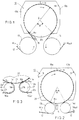
- Figure 1 is a schematic side view of a first embodiment of the invention.
- Figure 2 illustrates a second embodiment of the invention in a way similar to Fig. 1.
- Figure 3 is an illustration in part of a third embodiment of the invention.
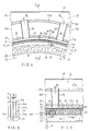
- Figure 4 is a vertical sectional view in the machine direction of the mantle of a Yankee cylinder in accordance with the invention and of the mantle of its blowing-on hood.
- Figure 5 is a sectional view taken along the line V-V in Fig. 4.
- Figure 6 shows the detail DET encircled in Fig. 5 on an enlarged scale.
- Figure 7 illustrates the process diagram of a preferred embodiment of the method and the device in accordance with the invention.
- the blowing-on hood 10 is divided by a transverse partition wall 11 into two compartments 10a and 10b, in which it is possible to apply drying parameters different from compartment to compartment.
- the web W in to be dried is passed on a relatively permeable drying fabric 12 over the first steam-heated drying cylinder 13, on which at least pre-heating and possibly also pre-drying of the web W is performed. After this, the web W is transferred on the straight run of the fabric 12 onto the cylinder 20.
- a positive pressure tends to be induced, which attempts to separate the web W from the fabric 12. This positive pressure is counteracted by means of a blow box 15, by whose means air is ejected out of the inlet nip N+, thereby attempting to bring the nip to the normal pressure or to a slight negative pressure.
- the web W runs on the sector 360° - ⁇ around the cylinder 20 and leaves the cylinder and the interior of the hood 10 at end of said sector, passing on the straight run of the fabric 12 onto the latter drying cylinder 14, on which the web W is after-dried.
- the dried web W out is transferred further to reeling.
- two through-dryers in accordance with the invention placed one after the other, which dryers are preferably arranged to operate so that the web sides are reversed in the latter drying stage. Between the different drying stages, it is preferable to employ closed draw in order to ensure a sufficiently high web speed.
- the dryer shown in Fig. 2 is in the other respects similar to that shown in Fig. 1 except that therein the web W in is passed on the fabric 12 around the first paper guide roll 13a onto the cylinder 20 and removed from said cylinder on the latter paper guide roll 14a, so that heated drying cylinders are not employed in this embodiment.
- the sector ⁇ is also considerably smaller than in Fig. 1.
- Fig. 3 differs from the concepts of Figs. 1 and 2 in the respect that the web W in is brought on the first drying fabric 12a around the suction sector 16a of the suction-transfer roll 16.
- the web W is separated from the first fabric 12a in the transfer nip N a with slight load, which nip is formed between the cylinder 20 and the suction-transfer roll 16.
- the web W is transferred in the transfer nip N b of the second suction-transfer roll 17 onto the second fabric 12b, and on support of said fabric further over the suction zone 17a of the second suction-transfer roll 17.
- Figs. 4, 5 and 6 disclose the construction in accordance with the invention of the drying cylinder and of the blowing-on hood 10.
- the blowing-on hood 10 is provided with outer walls 19, which define exhaust spaces 10c in their interior. Inside these spaces 10c, there are two walls 27a and 27b shaped as parts of a circular cylinder, of which walls the inner wall 27b is placed at the distance of a small free gap 18 from the free outer face of the web W, which runs on the fabric 12 or on the wire sock 21.
- the partition walls 27a and 27b define a space 10d.
- the open area formed by the nozzle holes 29, i.e. the percentage of holes, is, as a rule, in a range of 1...6 % of the area of the wall 27a.
- the mantle 23 of the flow-through cylinder 20 is provided with axial bores 25, through which a flow of cooling water WA has been arranged in a way that will come out later. Between the bores 25 extending over the entire length of the mantle 23 there are radial bores 26, whose outer orifices are provided with widened portions 26a. On the outer face of the cylinder mantle 23, there is a permeable outer mantle 24, which is, according to Fig. 6, made of profile band 24a by winding.
- the profile band 24a is provided with pin-shaped spacer pieces 24b, which define gaps 24c between the profile-band layers, through which gaps flow of medium can take place through the outer mantle 24 in the direction of the arrow B.
- the spacer pieces 24b are, for example, pin-shaped parts of circular section, which are placed on the profile band 24a in two rows with suitably small intervals.
- the gaps 24c between the profile bands 24a are opened into the widenings 26a in the bores 26.
- the mantle 23 and its outer part 24 are permeable into the interior space 22 of the cylinder 20.
- a corresponding permeable mantle layer which is made, e.g., of a felt-like or mesh-like material or of a sintered material which is provided with capillaries.
- Fig. 7 illustrates a preferred embodiment of the drying process.
- the combustion unit 32a in which the blowing-on air for the web W is heated, e.g., to about 350°C.
- exhaust-air flows are passed into the space 10c, and from there further through the duct 35 to the heat recovery system 34 and from it further, by means of the blower 33a, as recirculation air I k , to be combined with the replacement air flow I in .
- a corresponding system operates in the latter compartment 10b in the blowing-on hood 10, which compartment is separated by the partition walls 11 at the spaces 10c and 10d.
- the latter compartment 10b also includes a drying-air system similar to that described above and comprising a replacement-air duct 31b, a combustion unit 32b, a recirculation-air duct 35b, and a circulation air blower 33b and a heat-recovery system 34.
- a flow of cooling water WA is passed by means of a cooling-water pump 36 along the duct 37 into the cylinder, from where it is distributed by means of a pipe duct 37a into a ring pipe 37b and through branch pipes 37c branched from same into the bores 25 in the cylinder mantle 23.
- a cooling-water pump 36 For the purpose of cooling the mantle 23 of the cylinder 20, a flow of cooling water WA is passed by means of a cooling-water pump 36 along the duct 37 into the cylinder, from where it is distributed by means of a pipe duct 37a into a ring pipe 37b and through branch pipes 37c branched from same into the bores 25 in the cylinder mantle 23.
- branch pipes 37c branched from same into the bores 25 in the cylinder mantle 23.
- negative pressure is produced, which is preferably of an order of 10...30 kPa.
- the suction duct 38 communicates with a suction duct 39, which communicates with a suction pump 40, which removes both air and water that has been separated from the web W.
- the water vapour evaporated from the interior of the web W is carried through the fabric 12;21 onto the cooled cylinder face 24,23, where the condensed water is sucked into the capillaries or grooves 24c that form the hollow face and further into the bores 26a,26 by the effect of the negative pressure that prevails in the interior 22 of the cylinder 20.
- the water is also drained mainly in the area ⁇ not covered by the web W, in which area the water operates as a "seal" in the ducts 26,26a,24c in the mantle 23 in the way of a water seal, whereby the use of a relatively high negative pressure in the interior 22 of the cylinder 20 is possible.
- the drying takes place so that thermal energy is transferred from the hot air blown B1 onto the web W into the wet web W, whereby evaporation of water takes place in the web W.
- On the outer face of the web W nothing prevents the evaporated vapour from being carried into the exhaust ducts 18,28,10c.
- the web W is supported by a mesh-like drying fabric 12; 21.
- temperature of the fabric 12;21 and of the outer face 23,24 of the cylinder 20 is kept low, the vapour evaporated from the inner face of the web W is condensed as water onto said cold faces. The colder the faces, the lower can the temperature of the water vapour be that is condensed on said faces.
- the negative pressure in the interior 22 of the cylinder 20 must be of an order of 10...30 kPa.
- the vaporization temperature of water is of an order of 90°C.
- the temperature of the inner face of the web W is higher than 90°C, the water contained in it is vaporized.
- the temperature of the cooled outer face of the cylinder 20 is lower than 90°C, the water vapour tends to be condensed on it.
- a difference in pressure acts upon the web W throughout the entire process of drying, which difference in pressure fixes the web firmly onto the outer face of the fabric 12 or of the corresponding wire sock 21.
- the substantial advantage is obtained that, during the drying, the web cannot shrink in the transverse direction, which has been the case, e.g., in the prior-art cylinder dryers.
- This shrinkage has a number of detrimental effects, e.g., on different transverse profiles of the web, such as the profiles of fibre orientation.
- This problem is also solved in the present invention in a novel way.
- the scope of the invention also includes embodiments of equipment in which no fabric 12 or equivalent wire sock 21 is employed.
- a capillary face 24 is employed as does not mark the web to a detrimental extent, the face of said web entering in direct contact with said capillary face.
Landscapes
- Drying Of Solid Materials (AREA)
- Paper (AREA)
- Diaphragms For Electromechanical Transducers (AREA)
- Golf Clubs (AREA)
- Adhesives Or Adhesive Processes (AREA)
- Ultra Sonic Daignosis Equipment (AREA)
Applications Claiming Priority (2)
| Application Number | Priority Date | Filing Date | Title |
|---|---|---|---|
| FI920942 | 1992-03-02 | ||
| FI920942A FI87669C (fi) | 1992-03-02 | 1992-03-02 | Foerfarande och tork vid torkning av papper |
Publications (2)
| Publication Number | Publication Date |
|---|---|
| EP0559628A1 true EP0559628A1 (fr) | 1993-09-08 |
| EP0559628B1 EP0559628B1 (fr) | 1997-04-16 |
Family
ID=8534857
Family Applications (1)
| Application Number | Title | Priority Date | Filing Date |
|---|---|---|---|
| EP93850038A Expired - Lifetime EP0559628B1 (fr) | 1992-03-02 | 1993-02-26 | Procédé et dispositif pour le séchage du papier |
Country Status (6)
| Country | Link |
|---|---|
| US (1) | US5383288A (fr) |
| EP (1) | EP0559628B1 (fr) |
| AT (1) | ATE151827T1 (fr) |
| CA (1) | CA2090783C (fr) |
| DE (1) | DE69309758T2 (fr) |
| FI (1) | FI87669C (fr) |
Cited By (6)
| Publication number | Priority date | Publication date | Assignee | Title |
|---|---|---|---|---|
| EP0620313A3 (en) * | 1993-03-22 | 1994-11-23 | Valmet Paper Machinery Inc | Drying method and drying module, as well as dryer sections that make use of same, in particular for a high-speed paper machine. |
| WO2000014329A1 (fr) * | 1998-09-04 | 2000-03-16 | Equitor Oy | Procede et section de sechage pour l'essorage d'une bande fibreuse |
| EP0989232A3 (fr) * | 1998-09-11 | 2001-01-10 | Voith Paper Patent GmbH | Section de séchage |
| EP1158092A3 (fr) * | 2000-05-24 | 2002-04-24 | Voith Paper Patent GmbH | Section de séchage |
| EP1279764A3 (fr) * | 2001-07-27 | 2004-05-12 | Tokushu Paper Manufacturing Co. Ltd | Bande de matière et procédé et dispositif pour son séchage |
| US7802377B2 (en) | 2005-01-05 | 2010-09-28 | Voith Patent Gmbh | Drying cylinder |
Families Citing this family (28)
| Publication number | Priority date | Publication date | Assignee | Title |
|---|---|---|---|---|
| SE504645C2 (sv) * | 1995-07-12 | 1997-03-24 | Valmet Karlstad Ab | Pappersmaskin för framställning av mjukpapper |
| US6119362A (en) * | 1996-06-19 | 2000-09-19 | Valmet Corporation | Arrangements for impingement drying and/or through-drying of a paper or material web |
| DE19651191A1 (de) * | 1996-12-10 | 1998-06-18 | Voith Sulzer Papiermasch Gmbh | Trockenpartie einer Maschine zur Herstellung einer Materialbahn |
| CA2197254C (fr) * | 1997-02-11 | 2005-08-02 | Stanley H. Sather | Tuyauterie et methode pour sechoirs de pulpe |
| CA2234305A1 (fr) * | 1997-04-03 | 1998-10-03 | Fort James Corporation | Secheur a air traversant haute intensite pour conversion de machines a papier classiques a presse humide |
| US6003245A (en) * | 1997-04-22 | 1999-12-21 | Valmet Corporation | Method for optimizing of evaporation drying of paper, runnability, and of paper quality as well as dryer section that makes use of the method in a paper machine |
| US6101735A (en) * | 1997-04-22 | 2000-08-15 | Valmet Corporation | Dryer section in a paper machine in which impingement and/or ventilation hoods are used |
| FI103999B1 (fi) * | 1997-04-22 | 1999-10-29 | Valmet Corp | Kuivatusyksikkö ja niitä soveltava kuivatusosa |
| FI104000B (fi) * | 1998-04-03 | 1999-10-29 | Valmet Corp | Telan, sylinterin tai vastaavan ympärille sovitettu päällepuhallusjärjestelmä paperikoneen tai vastaavan kuivatusosassa |
| US6079116A (en) * | 1998-11-06 | 2000-06-27 | Valmet-Karlstad Ab | Duct configuration for a through-air drying apparatus in a papermaking machine |
| DE19944267A1 (de) * | 1999-09-15 | 2001-03-22 | Voith Paper Patent Gmbh | Verfahren und Vorrichtung zum Trocknen einer Materialbahn |
| US6432267B1 (en) * | 1999-12-16 | 2002-08-13 | Georgia-Pacific Corporation | Wet crepe, impingement-air dry process for making absorbent sheet |
| DE10047663A1 (de) * | 2000-09-26 | 2002-04-11 | Voith Paper Patent Gmbh | Anordnung zum Trocknen einer Materialbahn |
| US6729386B1 (en) | 2001-01-22 | 2004-05-04 | Stanley H. Sather | Pulp drier coil with improved header |
| WO2004037696A2 (fr) * | 2002-10-19 | 2004-05-06 | Koenig & Bauer Aktiengesellschaft | Elements de guidage de machine de production ou de traitement de bandes de matiere |
| US7125473B2 (en) * | 2003-09-12 | 2006-10-24 | International Paper Company | Apparatus and method for conditioning a web on a papermaking machine |
| DE102004017811A1 (de) * | 2004-04-13 | 2005-10-27 | Voith Paper Patent Gmbh | Beheizter Zylinder |
| DE102005000795A1 (de) | 2005-01-05 | 2006-07-13 | Voith Paper Patent Gmbh | Vorrichtung und Verfahren zur Herstellung und/oder Veredelung einer Faserstoffbahn |
| DE102006015796A1 (de) * | 2005-05-13 | 2006-11-16 | Voith Patent Gmbh | Trockenzylinder |
| DE102005057638A1 (de) * | 2005-12-02 | 2007-06-06 | Voith Patent Gmbh | Bahnüberwachung |
| FI124037B (fi) * | 2008-09-03 | 2014-02-14 | Ev Group Oy | Laite sekä menetelmä paperin irtoamisen parantamiseksi paperikoneen kuivatussylinteriltä |
| WO2015030766A1 (fr) * | 2013-08-29 | 2015-03-05 | Hewlett-Packard Development Company, L.P. | Séchage à humidité variable |
| ITFI20130241A1 (it) * | 2013-10-15 | 2015-04-16 | Celli Paper S P A A | "componenti di impianti per la produzione di carta ad umido" |
| EP2963176B1 (fr) * | 2015-04-23 | 2017-03-15 | Valmet S.p.A. | Agencement de hotte de séchage yankee, cylindre de séchage yankee équipé d'un agencement de hotte de séchage yankee et procédé de séchage d'une bande fibreuse |
| CN106283816B (zh) * | 2015-05-29 | 2020-04-10 | 金红叶纸业集团有限公司 | 干燥系统及其造纸方法 |
| CN106283815B (zh) * | 2015-05-29 | 2020-04-10 | 金红叶纸业集团有限公司 | 干燥系统及其造纸方法 |
| ITUA20163958A1 (it) * | 2016-05-31 | 2017-12-01 | Uteco Converting Spa | Macchina per la stampa digitale su nastro. |
| WO2019231502A1 (fr) * | 2018-05-31 | 2019-12-05 | Valmet, Inc. | Systèmes et procédés de séchage et de liaison à air traversant |
Citations (4)
| Publication number | Priority date | Publication date | Assignee | Title |
|---|---|---|---|---|
| US3541697A (en) * | 1968-08-01 | 1970-11-24 | Aer Corp | High velocity through-drying system |
| DE2358577A1 (de) * | 1973-11-24 | 1975-05-28 | Voith Gmbh J M | Zylinder fuer papiermaschinen o.dgl. |
| US3956832A (en) * | 1974-09-13 | 1976-05-18 | Beloit Corporation | Web dryer arrangement |
| DE2721146A1 (de) * | 1977-05-11 | 1978-11-16 | Schmidt Erwepa Maschf | Papiermaschine, insbesondere zur herstellung von tissue-papier |
Family Cites Families (5)
| Publication number | Priority date | Publication date | Assignee | Title |
|---|---|---|---|---|
| SE342273B (fr) * | 1965-09-23 | 1972-01-31 | Svenska Flaektfabriken Ab | |
| FI50721C (fi) * | 1972-03-29 | 1976-06-10 | Valmet Oy | Tissue-paperin valmistukseen tarkoitettu paperikone. |
| FI54164C (fi) * | 1977-07-08 | 1978-10-10 | Nokia Oy Ab | Foerfarande och anordning foer loestagning av en tissuepappersbana fraon pick-up-vaevnaden och foer dess oeverfoering till en genomstroemningstork |
| FI61537C (fi) * | 1981-02-19 | 1982-08-10 | Tampella Oy Ab | Foerfarande och anlaeggning foer kontinuerlig torkning av en pappers- eller liknande poroes bana |
| FI69141C (fi) * | 1984-10-09 | 1985-12-10 | Tampella Oy Ab | Foerfarande och anordning foer torkning av en pappersbana eller liknande |
-
1992
- 1992-03-02 FI FI920942A patent/FI87669C/fi active IP Right Grant
-
1993
- 1993-02-26 EP EP93850038A patent/EP0559628B1/fr not_active Expired - Lifetime
- 1993-02-26 AT AT93850038T patent/ATE151827T1/de not_active IP Right Cessation
- 1993-02-26 DE DE69309758T patent/DE69309758T2/de not_active Expired - Fee Related
- 1993-03-02 US US08/025,191 patent/US5383288A/en not_active Expired - Fee Related
- 1993-03-02 CA CA002090783A patent/CA2090783C/fr not_active Expired - Fee Related
Patent Citations (4)
| Publication number | Priority date | Publication date | Assignee | Title |
|---|---|---|---|---|
| US3541697A (en) * | 1968-08-01 | 1970-11-24 | Aer Corp | High velocity through-drying system |
| DE2358577A1 (de) * | 1973-11-24 | 1975-05-28 | Voith Gmbh J M | Zylinder fuer papiermaschinen o.dgl. |
| US3956832A (en) * | 1974-09-13 | 1976-05-18 | Beloit Corporation | Web dryer arrangement |
| DE2721146A1 (de) * | 1977-05-11 | 1978-11-16 | Schmidt Erwepa Maschf | Papiermaschine, insbesondere zur herstellung von tissue-papier |
Cited By (12)
| Publication number | Priority date | Publication date | Assignee | Title |
|---|---|---|---|---|
| EP0620313A3 (en) * | 1993-03-22 | 1994-11-23 | Valmet Paper Machinery Inc | Drying method and drying module, as well as dryer sections that make use of same, in particular for a high-speed paper machine. |
| US5495678A (en) * | 1993-03-22 | 1996-03-05 | Valmet Paper Machinery, Inc. | Drying module and dryer sections that make use of same, in particular for a high-speed paper machine |
| US5653041A (en) * | 1993-03-22 | 1997-08-05 | Valmet Corporation | Drying method and drying module as well as dryer sections that make use of same, in particular for a high-speed paper machine |
| EP1146169A3 (fr) * | 1993-03-22 | 2002-03-06 | Metso Paper, Inc. | Procédé et module de séchage ainsi que leur application dans des sections de séchage, en particulier pour des machines à papier à grande vitesse |
| WO2000014329A1 (fr) * | 1998-09-04 | 2000-03-16 | Equitor Oy | Procede et section de sechage pour l'essorage d'une bande fibreuse |
| US6473997B1 (en) | 1998-09-04 | 2002-11-05 | Equitor Oy | Method and drying section for dewatering a fibrous web |
| EP0989232A3 (fr) * | 1998-09-11 | 2001-01-10 | Voith Paper Patent GmbH | Section de séchage |
| US6294050B1 (en) | 1998-09-11 | 2001-09-25 | Voith Sulzer Papiertechnik Patent Gmbh | Drying end of a machine for the production of a material web and method of drying a material web |
| EP1158092A3 (fr) * | 2000-05-24 | 2002-04-24 | Voith Paper Patent GmbH | Section de séchage |
| US6658758B2 (en) | 2000-05-24 | 2003-12-09 | Voith Paper Patent Gmbh | Drying section with impingement drying unit |
| EP1279764A3 (fr) * | 2001-07-27 | 2004-05-12 | Tokushu Paper Manufacturing Co. Ltd | Bande de matière et procédé et dispositif pour son séchage |
| US7802377B2 (en) | 2005-01-05 | 2010-09-28 | Voith Patent Gmbh | Drying cylinder |
Also Published As
| Publication number | Publication date |
|---|---|
| DE69309758D1 (de) | 1997-05-22 |
| CA2090783A1 (fr) | 1993-09-03 |
| FI87669C (fi) | 1993-02-10 |
| FI920942A0 (fi) | 1992-03-02 |
| CA2090783C (fr) | 1998-05-19 |
| US5383288A (en) | 1995-01-24 |
| EP0559628B1 (fr) | 1997-04-16 |
| ATE151827T1 (de) | 1997-05-15 |
| DE69309758T2 (de) | 1997-09-18 |
| FI87669B (fi) | 1992-10-30 |
Similar Documents
| Publication | Publication Date | Title |
|---|---|---|
| EP0559628B1 (fr) | Procédé et dispositif pour le séchage du papier | |
| US5653041A (en) | Drying method and drying module as well as dryer sections that make use of same, in particular for a high-speed paper machine | |
| US4124942A (en) | Method and apparatus for controlling the moisture content of a web of sheet material | |
| EP0655528B1 (fr) | Procédé dans le séchage d'une bande de papier ainsi q'une section de séchage d'une machine à papier | |
| FI69141C (fi) | Foerfarande och anordning foer torkning av en pappersbana eller liknande | |
| EP0574366B1 (fr) | Procédé et dispositif pour intensifier l'opération d'une presse yankee dans une machine à fabriquer un papier absorbant | |
| US6523278B1 (en) | Dryer section | |
| US3384973A (en) | Ventilating dryers | |
| KR19980703814A (ko) | 건조기부 콘셉트 및 제지/판지 웨브의 건조방법 | |
| EP1664424B1 (fr) | Appareil de sechage d'une bande de tissu | |
| WO1997019223A1 (fr) | Appareil pour secher une bande de fibres | |
| US6094838A (en) | Curl and profile correction with high velocity hoods | |
| CA2211185A1 (fr) | Partie de sechoir a un seul etage dote de deux cylindres inverseurs | |
| US1595238A (en) | Vacuum seal, method and apparatus | |
| US6706150B1 (en) | Method and arrangement of impingement for blowing compensation of a tendency of curling of a paper board web to be treated as well as a paper or board machine | |
| KR20000005438A (ko) | 섬유 웨브용 건조 장치의 에너지 활용 방법 및 장치 | |
| KR20000005439A (ko) | 서ㅁ유 웨브용 건조 장치의 에너지 활용 방법 및 장치 | |
| FI106135B (fi) | Paperikoneen kuivatusryhmä/kuivatusosa, kuivatusmoduliyksikkö ja menetelmä paperirainan kuivattamiseksi | |
| FI69143B (fi) | Torkningsfoerfarande samt flercylindertork i en pappersmaskin | |
| US5850701A (en) | Dryer group with controlled heating and cooling of a paper web in a paper-making machine |
Legal Events
| Date | Code | Title | Description |
|---|---|---|---|
| PUAI | Public reference made under article 153(3) epc to a published international application that has entered the european phase |
Free format text: ORIGINAL CODE: 0009012 |
|
| AK | Designated contracting states |
Kind code of ref document: A1 Designated state(s): AT DE FR GB IT SE |
|
| 17P | Request for examination filed |
Effective date: 19940215 |
|
| GRAG | Despatch of communication of intention to grant |
Free format text: ORIGINAL CODE: EPIDOS AGRA |
|
| 17Q | First examination report despatched |
Effective date: 19960412 |
|
| GRAH | Despatch of communication of intention to grant a patent |
Free format text: ORIGINAL CODE: EPIDOS IGRA |
|
| RAP1 | Party data changed (applicant data changed or rights of an application transferred) |
Owner name: VALMET CORPORATION |
|
| GRAH | Despatch of communication of intention to grant a patent |
Free format text: ORIGINAL CODE: EPIDOS IGRA |
|
| GRAA | (expected) grant |
Free format text: ORIGINAL CODE: 0009210 |
|
| AK | Designated contracting states |
Kind code of ref document: B1 Designated state(s): AT DE FR GB IT SE |
|
| PG25 | Lapsed in a contracting state [announced via postgrant information from national office to epo] |
Ref country code: FR Effective date: 19970416 |
|
| REF | Corresponds to: |
Ref document number: 151827 Country of ref document: AT Date of ref document: 19970515 Kind code of ref document: T |
|
| REF | Corresponds to: |
Ref document number: 69309758 Country of ref document: DE Date of ref document: 19970522 |
|
| PG25 | Lapsed in a contracting state [announced via postgrant information from national office to epo] |
Ref country code: SE Effective date: 19970716 |
|
| EN | Fr: translation not filed | ||
| PLBE | No opposition filed within time limit |
Free format text: ORIGINAL CODE: 0009261 |
|
| STAA | Information on the status of an ep patent application or granted ep patent |
Free format text: STATUS: NO OPPOSITION FILED WITHIN TIME LIMIT |
|
| 26N | No opposition filed | ||
| PGFP | Annual fee paid to national office [announced via postgrant information from national office to epo] |
Ref country code: AT Payment date: 20000221 Year of fee payment: 8 |
|
| PGFP | Annual fee paid to national office [announced via postgrant information from national office to epo] |
Ref country code: GB Payment date: 20000223 Year of fee payment: 8 |
|
| PG25 | Lapsed in a contracting state [announced via postgrant information from national office to epo] |
Ref country code: GB Free format text: LAPSE BECAUSE OF NON-PAYMENT OF DUE FEES Effective date: 20010226 Ref country code: AT Free format text: LAPSE BECAUSE OF NON-PAYMENT OF DUE FEES Effective date: 20010226 |
|
| GBPC | Gb: european patent ceased through non-payment of renewal fee |
Effective date: 20010226 |
|
| PGFP | Annual fee paid to national office [announced via postgrant information from national office to epo] |
Ref country code: DE Payment date: 20020207 Year of fee payment: 10 |
|
| PG25 | Lapsed in a contracting state [announced via postgrant information from national office to epo] |
Ref country code: DE Free format text: LAPSE BECAUSE OF NON-PAYMENT OF DUE FEES Effective date: 20030902 |
|
| PG25 | Lapsed in a contracting state [announced via postgrant information from national office to epo] |
Ref country code: IT Free format text: LAPSE BECAUSE OF NON-PAYMENT OF DUE FEES Effective date: 20050226 |