EP0559977A1 - Ensemble de cathéther à usages multiples - Google Patents
Ensemble de cathéther à usages multiples Download PDFInfo
- Publication number
- EP0559977A1 EP0559977A1 EP92302094A EP92302094A EP0559977A1 EP 0559977 A1 EP0559977 A1 EP 0559977A1 EP 92302094 A EP92302094 A EP 92302094A EP 92302094 A EP92302094 A EP 92302094A EP 0559977 A1 EP0559977 A1 EP 0559977A1
- Authority
- EP
- European Patent Office
- Prior art keywords
- wall
- patient
- tubular portion
- apparatus defined
- tube
- Prior art date
- Legal status (The legal status is an assumption and is not a legal conclusion. Google has not performed a legal analysis and makes no representation as to the accuracy of the status listed.)
- Granted
Links
Images



Classifications
-
- A—HUMAN NECESSITIES
- A61—MEDICAL OR VETERINARY SCIENCE; HYGIENE
- A61M—DEVICES FOR INTRODUCING MEDIA INTO, OR ONTO, THE BODY; DEVICES FOR TRANSDUCING BODY MEDIA OR FOR TAKING MEDIA FROM THE BODY; DEVICES FOR PRODUCING OR ENDING SLEEP OR STUPOR
- A61M25/00—Catheters; Hollow probes
- A61M25/01—Introducing, guiding, advancing, emplacing or holding catheters
- A61M25/0105—Steering means as part of the catheter or advancing means; Markers for positioning
- A61M25/0111—Aseptic insertion devices
-
- A—HUMAN NECESSITIES
- A61—MEDICAL OR VETERINARY SCIENCE; HYGIENE
- A61M—DEVICES FOR INTRODUCING MEDIA INTO, OR ONTO, THE BODY; DEVICES FOR TRANSDUCING BODY MEDIA OR FOR TAKING MEDIA FROM THE BODY; DEVICES FOR PRODUCING OR ENDING SLEEP OR STUPOR
- A61M16/00—Devices for influencing the respiratory system of patients by gas treatment, e.g. ventilators; Tracheal tubes
- A61M16/04—Tracheal tubes
- A61M16/0463—Tracheal tubes combined with suction tubes, catheters or the like; Outside connections
-
- A—HUMAN NECESSITIES
- A61—MEDICAL OR VETERINARY SCIENCE; HYGIENE
- A61M—DEVICES FOR INTRODUCING MEDIA INTO, OR ONTO, THE BODY; DEVICES FOR TRANSDUCING BODY MEDIA OR FOR TAKING MEDIA FROM THE BODY; DEVICES FOR PRODUCING OR ENDING SLEEP OR STUPOR
- A61M16/00—Devices for influencing the respiratory system of patients by gas treatment, e.g. ventilators; Tracheal tubes
- A61M16/04—Tracheal tubes
- A61M16/0475—Tracheal tubes having openings in the tube
- A61M16/0477—Tracheal tubes having openings in the tube with incorporated means for delivering or removing fluids
- A61M16/0484—Tracheal tubes having openings in the tube with incorporated means for delivering or removing fluids at the distal end
-
- A—HUMAN NECESSITIES
- A61—MEDICAL OR VETERINARY SCIENCE; HYGIENE
- A61M—DEVICES FOR INTRODUCING MEDIA INTO, OR ONTO, THE BODY; DEVICES FOR TRANSDUCING BODY MEDIA OR FOR TAKING MEDIA FROM THE BODY; DEVICES FOR PRODUCING OR ENDING SLEEP OR STUPOR
- A61M16/00—Devices for influencing the respiratory system of patients by gas treatment, e.g. ventilators; Tracheal tubes
- A61M16/04—Tracheal tubes
- A61M16/0486—Multi-lumen tracheal tubes
-
- A—HUMAN NECESSITIES
- A61—MEDICAL OR VETERINARY SCIENCE; HYGIENE
- A61M—DEVICES FOR INTRODUCING MEDIA INTO, OR ONTO, THE BODY; DEVICES FOR TRANSDUCING BODY MEDIA OR FOR TAKING MEDIA FROM THE BODY; DEVICES FOR PRODUCING OR ENDING SLEEP OR STUPOR
- A61M16/00—Devices for influencing the respiratory system of patients by gas treatment, e.g. ventilators; Tracheal tubes
- A61M16/08—Bellows; Connecting tubes ; Water traps; Patient circuits
- A61M16/0816—Joints or connectors
- A61M16/0833—T- or Y-type connectors, e.g. Y-piece
-
- A—HUMAN NECESSITIES
- A61—MEDICAL OR VETERINARY SCIENCE; HYGIENE
- A61M—DEVICES FOR INTRODUCING MEDIA INTO, OR ONTO, THE BODY; DEVICES FOR TRANSDUCING BODY MEDIA OR FOR TAKING MEDIA FROM THE BODY; DEVICES FOR PRODUCING OR ENDING SLEEP OR STUPOR
- A61M1/00—Suction or pumping devices for medical purposes; Devices for carrying-off, for treatment of, or for carrying-over, body-liquids; Drainage systems
- A61M1/71—Suction drainage systems
- A61M1/77—Suction-irrigation systems
-
- A—HUMAN NECESSITIES
- A61—MEDICAL OR VETERINARY SCIENCE; HYGIENE
- A61M—DEVICES FOR INTRODUCING MEDIA INTO, OR ONTO, THE BODY; DEVICES FOR TRANSDUCING BODY MEDIA OR FOR TAKING MEDIA FROM THE BODY; DEVICES FOR PRODUCING OR ENDING SLEEP OR STUPOR
- A61M1/00—Suction or pumping devices for medical purposes; Devices for carrying-off, for treatment of, or for carrying-over, body-liquids; Drainage systems
- A61M1/84—Drainage tubes; Aspiration tips
- A61M1/85—Drainage tubes; Aspiration tips with gas or fluid supply means, e.g. for supplying rinsing fluids or anticoagulants
-
- Y—GENERAL TAGGING OF NEW TECHNOLOGICAL DEVELOPMENTS; GENERAL TAGGING OF CROSS-SECTIONAL TECHNOLOGIES SPANNING OVER SEVERAL SECTIONS OF THE IPC; TECHNICAL SUBJECTS COVERED BY FORMER USPC CROSS-REFERENCE ART COLLECTIONS [XRACs] AND DIGESTS
- Y10—TECHNICAL SUBJECTS COVERED BY FORMER USPC
- Y10S—TECHNICAL SUBJECTS COVERED BY FORMER USPC CROSS-REFERENCE ART COLLECTIONS [XRACs] AND DIGESTS
- Y10S128/00—Surgery
- Y10S128/911—Unilimb inhalation-exhalation breathing tubes
-
- Y—GENERAL TAGGING OF NEW TECHNOLOGICAL DEVELOPMENTS; GENERAL TAGGING OF CROSS-SECTIONAL TECHNOLOGIES SPANNING OVER SEVERAL SECTIONS OF THE IPC; TECHNICAL SUBJECTS COVERED BY FORMER USPC CROSS-REFERENCE ART COLLECTIONS [XRACs] AND DIGESTS
- Y10—TECHNICAL SUBJECTS COVERED BY FORMER USPC
- Y10S—TECHNICAL SUBJECTS COVERED BY FORMER USPC CROSS-REFERENCE ART COLLECTIONS [XRACs] AND DIGESTS
- Y10S604/00—Surgery
- Y10S604/905—Aseptic connectors or couplings, e.g. frangible, piercable
Definitions
- One type of system used for applying oxygen and suction to a patient uses a T shaped connector through which a catheter is introduced through the patient's mouth into the lungs.
- the catheter tube or lumen is fed through a sponge or the like into the T connector and then into the patient.
- the sponge is directly in one of the branches of the T connector and when the catheter is withdrawn through the sponge, mucus is trapped on the sponge in the passageway ionto the patient and thus can be drawn into the patient's lungs. This is a dangerous situation for the patient.
- the prior art does not show a suctioning and oxygenating system which is a closed system which can prevent a patient from suffering oxygen depletion.
- the system of the invention includes means which renders it a closed system which prevents a patient from suffering oxygen depletion during use.
- a catheter assembly 10 embodying the invention includes a dual-purpose catheter assembly of the type described and claimed in U.S. Patent No. 4,595,005 and incorporated herein by reference.
- the catheter assembly shown in the patent includes a double lumen unit 22, having flexible plastic tubes or lumens 240 and 250 secured together for most of their lengths, one being used to supply oxygen and one being used to provide suction.
- the flexible lumen tubes preferably have different diameters and shapes to insure proper connections to associated apparatus and in one form they have a cross-section as shown in Fig. 3.
- the patient end 242 of the suction tube 250 is open and may have auxiliary holes not shown.
- the oxygen tube 240 may be open at its patient end and also includes auxiliary holes 280 along its patient end.
- the lumen tubes 240 and 250 are connected at one end to a valve 20 for permitting the application of oxygen and suction to a patient as described in the above-identified patent.
- the catheter is used with a hollow, generally T shaped connector 24 which is a tubular member, preferably of plastic, having a cross member 26 (shown oriented horizontally in Fig. 1) which represents the cross-bar of the T and has a front or patient end 32 which is adapted to be placed in a patient's mouth.
- the other end or rear end 34 of the cross member carries within it a dry or wet sponge 36 of suitable size which is adapted to clean the end of the catheter lumen unit 22 as the lumen unit is withdrawn from a patient.
- the sponge 36 has a through-hole 38 through which the catheter lumen assembly 22 of flexible tubes 240 and 250 is pushed into the patient.
- the hole 38 in the sponge matches the size and shape of the catheter lumen unit as shown in Fig. 3.
- a removable cap 42 is coupled to the rear end of the connector 24 to permit the sponge 36 to be removed and cleaned or replaced.
- the T connector 24 also includes an arm 28 which extends downwardly from the cross portion and this arm is adapted to be coupled to a source of oxygen to be introduced into the patient.
- the arm 28 may or may not be at 90 degrees to the cross member 26 so that the connector 24 need not be exactly T shaped.
- a wall 46 is provided in the cross member in the vicinity of the juncture of the arm 28 but on the side thereof closer to the rear end of the cross member and this wall 46 blocks the portion of the cross member behind it from the patient and the airway to the patient.
- the wall 46 has a generally central aperture 48.
- a hollow tubular sleeve 82 is also provided in the rear portion of the connector 24.
- the sleeve 82 which may be of plastic, has its rear end bearing against the front end of the sponge 36 to hold the sponge in place and its front end bears against the rear surface of the wall 46.
- the sleeve 82 does not obstruct opening 48 in the wall 46.
- Means is provided in the wall 46 for permitting the end 242 of the catheter lumen unit 22 to pass through and be directed into the patient.
- means is provided to block and unblock the opening 48 in the wall 46.
- This means in one embodiment shown in Figs 1 and 2, includes a solid slide plate 84 seated behind the wall 46 in the rear portion of rear chamber of the connector 24 and slidable in guides formed on the rear surface of the wall 46 or in guide depressions 86 formed in the front end of the sleeve 82 as seen in Fig. 4.
- the slide plate 84 includes an aperture 88 and it extends through the wall of the connector to provide external portions 94 by means of which the slide can be manipulated so that its aperture 88 can be aligned with the aperture 48 in the wall 46 or it can be manipulated so that the solid portion of the slide blocks the opening 48. With the opening 88 in the slide plate 84 aligned with the opening 48 in the wall 46, the catheter lumen unit 22 can pass through the aligned openings into the front portion of the T connector and into the patient.
- the plate 84 may also be mounted to rotate to achieve the desired blocking and unblocking of aperture 48.
- An accordion sleeve or covering 96 is provided coupled to the rear end of the cross arm 26 of the connector 24 and enclosing the length of the catheter lumen unit 22 with its rear end connected to the valve 20 or to associated apparatus.
- the sleeve 96 includes a plurality of vent holes 98.
- the covering 96 provides a protective enclosure and may take any suitable form other than accordion.
- the front or patient end of the T connector 24 is placed in the patient's mouth and the catheter lumen unit 22 is pushed through the sponge 36 into the aligned openings 48 and 88 in the wall 46 and slide plate 84, respectively, and through the remainder of the cross member 26 and into the patient.
- oxygen is fed through arm 28 and the front portion of the connector 24 into the patient.
- the catheter is withdrawn and it proceeds through the opening 48 in the wall 46 without any mucus which may be on it being deposited on the wall 46.
- the opening 48 is closed by suitably sliding the slide plate 84 and then as the catheter passes through the sponge 36, it is cleaned of mucus and other matter. Since, the mucus, if any, is located in a closed compartment of the connector 24 which is sealed off from the patient by wall 46, there is no way by which mucus can be drawn back into the patient.
- vent holes 280 at the patient end of the oxygen tube 240 lie outside the T connector and within the sleeve 96 so that oxygen can be vented when it is not being fed to a patient.
- the rear end 34 of the T connector 24 includes a portion 24A behind wall 46 containing the sleeve 82 and a rearward portion 24B containing the sponge 36.
- a first short tube is provided in the wall of the portion 24A extending from inside portion 24A to outside the T connector.
- the tube is generally vertically oriented.
- a second similar tube 116 is provided in the wall of the portion 24A and extending from inside portion 24A to the outside thereof.
- the tube 116 is generally vertically oriented and may be aligned with tube 114.
- the outer end of tube 114 has a removable cap 117 and the outer end of tube 116 has a removable cap 118.
- the tube 114 can be used to connect suction for cleaning out the T connector. While suction is applied, the tube 116 is held open as a vent, The tube 116 can also be held open as a vent when oxygen is fed into the valve from the oxygen source but it is not applied to the patient.
- valve 20 in order to render the apparatus described above a closed system as far as the patient is concerned so that oxygen cannot be lost by the patient through the catheter lumen unit, and valve 20 the catheter lumen unit is used with a valve mechanism 20 which is similar to that shown in the above-identified patent but embodies novel features not shown in the patent.
- the valve 20 comprises two cylindrical bodies 30 and 40 having circular cross-sections and rotatably coupled together.
- One body 30 includes a flat rear wall 44, through which first and second integral tubes 50 and 60 extend so that the two tubes lie inside amd outside the body and thus inside the valve 20 when it is assembled.
- the inner ends 51 and 61 of tubes 50 and 60 are as smooth as possible for a purpose to be described.
- Tube 50 is used for connection to a suction source and tube 60 for connection to an oxygen supply, and the suction tube 50 is preferably of larger diameter.
- a portion 70 of the inner wall of the body 30 (Fig. 8) near rear wall 44 is thickened or is of reduced inside diameter to provide on annular ledge 74 which acts as a stop far the leading end of body 40 when the two are assembled.
- the rear wall 44 of the body 30 also has a central hole 80 and a notched tab 90 which is formed integral with the body 30 and extends partly across the hole 80.
- the tab 90 has a notch or depression 92 across its outer surface.
- An operating finger tab 100 extends generally perpendicularly from the outer surface of the body 30 for manipulation by the operator of the catheter.
- the lower edge of tab 100 has a notch 102 for a purpose to be described.
- the second body 40 includes a rear wall 110, whose inner surface 112 is as smooth as possible, for a purpose to be described.
- the annular outer wall 120 of body 40 has a portion 122 of reduced thickness or smaller outside diameter at its leading end for insertion into body 30.
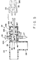
- the outer surface of the thicker portion 124 is provided with a region 130 of reduced thickness (Fig. 5) having a ledge 132 (figs. 5 and 6 ) where it joins the portion 122 of reduced thickness.
- An integral operating finger tab 140 extends generally perpendicularly from the thicker annular wall portion at one end of the portion 130 of reduced thickness.
- the finger tabs 100 and 140 are provided with roughened strips 142 on their outer opposite faces, shown only in Figs. 5, 6, and 7, to facilitate their manipulation by the user of the catheter.
- Two tubes 150 and 160 extend away from the wall 110, one 150 for oxygen and one 160 for suction.
- the two tubes 150 and 160 communicate with the inside of the body 40 through holes 152 and 162 in the rear wall 110.
- the rear wall 110 also has two holes 170 and 180 located on the same circumference as the two tubes 150 and 160, and a central opening 190.
- a small integral tab 200 having a notch 210 extends part way across the opening 190.
- the thin annular wall 122 of the body 40 fits snugly into the opening in body 30, and the leading end 212 butts up against the ledge 74. Similarly, the leading end 214 of body 30 butts up against ledge 216 where wall 122 meets wall 124 of the body 40. Also, the inner ends 51 and 61 of tubes 50 and 60 form a tight fit against the inner surface 112 of rear wall 110 of body 40 to provide an essentially leak-proof coupling between body 30 and body 40.
- the finger tab 100 slips over the rim 132, and the notch 102 in the lower surface thereof engages and locks in on the rim.
- the two bodies 30 and 40 are held together securely and tightly by means of a helical spring 218 which is secured at its ends in the notches 92 and 210 in the tabs 90 and 200.
- a helical spring 218 which is secured at its ends in the notches 92 and 210 in the tabs 90 and 200.
- one end of the spring is shaped like a hook and is secured to notch 92, and, with the other end grasped by a hooked instrument, the spring is rotated to bias it, and then its other end, which is also shaped like a hook, is set in notch 210 in tab 200, and the bodies are locked together.
- the spring holds bodies 30 and 40 tightly together with the inner portions 51 and 61 of tubes 50 and 60 snug against the inner surface 112 of end wall 110.
- the bias set into the spring serves to keep the bodies 30 and 40 rotated so that the finger tabs 100 and 140 are at their maximum distance apart. With this orientation of the bodies, the oxygen tube 60 is aligned with the oxygen feed tube 150 through its hole 152 in wall 110, and the suction tube 50 is aligned with hole 170 and the ambient atmosphere. When the tabs 100 and 140 are squeezed together, the suction tube 50 is aligned with suction tube 160 through its hole 162 in the wall 110, and the oxygen tube 60 is aligned with the hole 180 and the ambient atmosphere.
- the tube 50 is connected by flexible plastic tubing 220 to a source of suction (not shown) and the tube 60 is similarly connected by tubing 230 to an oxygen source (not shown).
- the oxygen and suction tubes 150 and 160 are connected to the flexible tubes 240 and 250, rerspectively, which are coupled to the tubes 150 and 160.
- the oxygen tube 240 is of smaller diameter than the suction tube 250.
- the tubes 240 and 250 are manufactured as a single unit, and they preferably have generally semicicrcular cross-sections with the flat portions thereof adjacent to each other as seen in Fig. 3. Tubes 150 and 160 are similarly semicircular in cross section.
- the tubes 240 and 250 are separated by a small amount at the valve ends to permit them to be handled and secured to the valve tubes 150 and 160.
- the unitary assembly of flexible tubes 240 and 250 is provided with well-defined grooves 268 between them as seen in Figs. 1 and 6 and it is manufactured so that there is a natural curvature built into it.
- both the built-in curvature and the difference in the diameters of the tubes 240 and 250 combine to impart controllability of the assembly by the operator and it permits easy buidance of the patient ends of the tubes into the throat and lungs.
- the grooves 260 act as a rake and loosen mucus which can be removed by suction.
- the flexible tubes 240 and 250 are coupled to the valve 20 through on adapter 310 (Fig. 1) which is described and claimed in copending application serial no. 270,057 filed November 14, 1988 which is incorporated herein by reference.
- the adapter 310 comprises a rigid plastic body having two through holes 320 and 330 and has front surface 340 and a rear surface 350.
- the holes 320 and 330 are shaped and dimensioned so that when the adapter is coupled to rigid tubes 150 and 160 on the patient side of the valve mechanism 20, hole 320 forms a tight fit with tube 160 and hole 330 forms a tight fit with tube 150.
- the finger tabs 100 end 140 are apart and all of the associated parts are arranged so that oxygen flows from the oxygen source, through tube 230, valve tubes 60 and 150 and lumen tube 240 and into the patient.
- the suction source is coupled through tube 50 to the valve hole 170 to the atmosphere.
- the tabs 100 and 140 are pressed together to align the suction tubes 50 and 160 to flexible tube 250 so that suction is administered and the oxygen source is connected to valve hole 180 to the atmosphere.
- the finger tabs 100 and 140 are released and suction is discontinued, and oxygen is applied again.
- Valve 20 is constructed so that the entrance openings inside the valve to rigid tubes 150 and 160 and their attached flexible tubes 240 end 250 are alternately blocked off from the patient as suction and oxygen are applied to the patient.
- this is achieved by providing a first solid boss or cylinder 260 on the inner surface 262 of the wall of valve portion 30 and positioned just beneath the tube 60.
- a similar second solid boss or cylinder 270 is provided on the surface 262 just beneath the tube 50.
- the two bosses are of such a length, like tubes 50 and 60, that they contact and form a tight fit against the inner surface 112 of valve portion 40 when the two parts 30 and 40 of the valve 20 are assembled.
- bosses 260 and 270 are positioned so that, when the source of oxygen is connected through tube 60, tube 150 and tube 240 to the patient and the suction tube is coupled to the opening to the atmosphere, boss 260 blocks the opening to tube 160 and to the lumen 250 to the patient so that the patient cannot breathe into the valve through this lumen.
- the source of oxygen is aligned with the opening to the atmosphere and the second boss 270 blocks the opening into tube 150 and to the oxygen lumen 240 to the patient.
- the patient cannot breathe into or from the valve 20 through the oxygem lumen.
- bosses 260 and 270 operate to provide a closed system as far as the patient is concerned and the lumens 240 and 250 to the patient are alternately blocked from the valve 20 as the patient is alternately oxygenated and suctioned. This prevents the patient's lungs from losing oxygen through the valve 20.
- a flexible cord 282 is secured between the rear end 34 of connector 24 and the adapter 31.
- the cord 282 permits the catheter assembly to be inserted into the patient but when the assembly is withdrawn, it limits the extent to which it con be withdrawn and thus prevents it from being removed from the connector 24.
- the rear chamber 24B of the T connector may be provided with a sleeve 353 having front and rear transverse walls 355 and 357 which have central openings 359 and 361 through which the double lumen catheter unit 22 passes in use.
- the openings 359 and 361 have a shape like the lumen unit 22 as seen in Fig. 3 and these openings are dimensionsed so that when the lumen unit is withdrawn after use, the walls 355 and 357, which define the openings 359 and 361, scrape mucus from the lumen tubes and thus clean them.
Landscapes
- Health & Medical Sciences (AREA)
- Pulmonology (AREA)
- Life Sciences & Earth Sciences (AREA)
- Anesthesiology (AREA)
- Engineering & Computer Science (AREA)
- Biomedical Technology (AREA)
- Heart & Thoracic Surgery (AREA)
- Hematology (AREA)
- Animal Behavior & Ethology (AREA)
- General Health & Medical Sciences (AREA)
- Public Health (AREA)
- Veterinary Medicine (AREA)
- Emergency Medicine (AREA)
- Biophysics (AREA)
- External Artificial Organs (AREA)
- Media Introduction/Drainage Providing Device (AREA)
Priority Applications (1)
| Application Number | Priority Date | Filing Date | Title |
|---|---|---|---|
| DE1992616809 DE69216809T2 (de) | 1992-03-11 | 1992-03-11 | Mehrzweckkathetereinrichtung |
Applications Claiming Priority (2)
| Application Number | Priority Date | Filing Date | Title |
|---|---|---|---|
| US50747790A | 1990-04-11 | 1990-04-11 | |
| US07/571,709 US5140983A (en) | 1990-04-11 | 1990-08-24 | Multi purpose catheter assembly |
Publications (2)
| Publication Number | Publication Date |
|---|---|
| EP0559977A1 true EP0559977A1 (fr) | 1993-09-15 |
| EP0559977B1 EP0559977B1 (fr) | 1997-01-15 |
Family
ID=27055870
Family Applications (1)
| Application Number | Title | Priority Date | Filing Date |
|---|---|---|---|
| EP92302094A Expired - Lifetime EP0559977B1 (fr) | 1990-04-11 | 1992-03-11 | Ensemble de cathéther à usages multiples |
Country Status (2)
| Country | Link |
|---|---|
| US (1) | US5140983A (fr) |
| EP (1) | EP0559977B1 (fr) |
Cited By (4)
| Publication number | Priority date | Publication date | Assignee | Title |
|---|---|---|---|---|
| WO1995028981A1 (fr) * | 1994-04-22 | 1995-11-02 | The Government Of The United States Of America, Represented By The Secretary Of The Department Of Health And Human Services | Systeme appliquant une pression positive continue aux voies aeriennes |
| US5537729A (en) * | 1991-09-12 | 1996-07-23 | The United States Of America As Represented By The Secretary Of The Department Of Health And Human Services | Method of making ultra thin walled wire reinforced endotracheal tubing |
| US8567401B2 (en) | 2009-09-18 | 2013-10-29 | Kimberly Clark Worldwide, Inc. | Looped tether for medical ventilating and aspirating devices |
| EP3081238A3 (fr) * | 2015-04-17 | 2017-02-15 | ShineIN Biotechnology Co., Ltd. | Tête d'aspiration/irrigation |
Families Citing this family (65)
| Publication number | Priority date | Publication date | Assignee | Title |
|---|---|---|---|---|
| US5279549A (en) * | 1991-01-04 | 1994-01-18 | Sherwood Medical Company | Closed ventilation and suction catheter system |
| US5333606A (en) * | 1992-04-24 | 1994-08-02 | Sherwood Medical Company | Method for using a respirator accessory access port and adaptor therefore |
| US5325850A (en) * | 1992-09-30 | 1994-07-05 | Smith Industries Medical Systems, Inc. | Suction catheter assemblies |
| US5349950A (en) * | 1992-10-28 | 1994-09-27 | Smiths Industries Medical Systems, Inc. | Suction catheter assemblies |
| US5404873A (en) * | 1993-06-16 | 1995-04-11 | King System Corporation Division Of Barco Molding, Inc. | Anesthesia circuit |
| US5364366A (en) * | 1993-06-22 | 1994-11-15 | Dlp, Inc. | Apparatus for removing an indwelling tube |
| US5433195A (en) * | 1993-09-30 | 1995-07-18 | Sherwood Medical Company | Respiratory support system |
| US5375589A (en) * | 1993-10-18 | 1994-12-27 | Bhatta; Krishna M. | Unique cleaning catheter |
| US5487381A (en) * | 1994-04-20 | 1996-01-30 | Jinotti; Walter J. | Closed system for treating pulmonary patient |
| US5735271A (en) * | 1994-05-18 | 1998-04-07 | Ballard Medical Products | Multiple access adaptors for monitoring, sampling, medicating, aspirating, and ventilating the respiratory tract of a patient |
| US5694922A (en) | 1994-05-18 | 1997-12-09 | Ballard Medical Products | Swivel tube connections with hermetic seals |
| US6494203B1 (en) | 1994-08-19 | 2002-12-17 | Ballard Medical Products | Medical aspirating/ventilating closed system improvements and methods |
| US5642726A (en) * | 1994-10-18 | 1997-07-01 | Alcove Medical, Inc. | Reduced internal volume neonatal suction adaptor |
| US5582161A (en) * | 1994-12-08 | 1996-12-10 | Sherwood Medical Company | Sheathed catheter adapter and method of use |
| US5511545A (en) * | 1995-01-04 | 1996-04-30 | Jinotti; Walter J. | Valve for pulmonary medical use |
| EP0827416A4 (fr) * | 1995-03-28 | 1999-06-09 | Ballard Med Prod | Gaine de catheter anti-contamination a barrieres de filtration/fermeture |
| US5932309A (en) * | 1995-09-28 | 1999-08-03 | Alliedsignal Inc. | Colored articles and compositions and methods for their fabrication |
| US6439231B1 (en) | 1996-11-18 | 2002-08-27 | Medlis Corp. | Artificial ventilation systems and components thereof, and methods for providing, assembling and utilizing same |
| US5778872A (en) * | 1996-11-18 | 1998-07-14 | Medlis, Inc. | Artificial ventilation system and methods of controlling carbon dioxide rebreathing |
| US6003511A (en) | 1996-11-18 | 1999-12-21 | Medlis Corp. | Respiratory circuit terminal for a unilimb respiratory device |
| US6702789B1 (en) * | 1997-03-11 | 2004-03-09 | Alcove Medical, Inc. | Catheter having insertion control mechanism and anti-bunching mechanism |
| FR2765111B1 (fr) * | 1997-06-30 | 1999-09-24 | Georges Boussignac | Sonde d'aspiration endotracheale pour patient sous ventilation artificielle |
| US6109259A (en) * | 1997-12-10 | 2000-08-29 | Spirit Medical Systems, Inc. | Gas supplying and substance suctioning relative to a patients trachea |
| US6227200B1 (en) | 1998-09-21 | 2001-05-08 | Ballard Medical Products | Respiratory suction catheter apparatus |
| US7021313B1 (en) | 1998-09-21 | 2006-04-04 | Ballard Medical Products | Respiratory suction catheter apparatus with improved valve and collar |
| BR9804529A (pt) * | 1998-10-23 | 2000-04-25 | Newmed Importadora Ltda | Dispositivo para realização de aspirador de secreções em pacientes entubados ou traquenostomizados e kit contendo um dispositivo para realização de aspiração de secreções em pacientes entubados ou tranqueostomizados. |
| US6102042A (en) | 1998-12-22 | 2000-08-15 | Respironics, Inc. | Insufflation system, attachment and method |
| US7431031B2 (en) * | 1998-12-22 | 2008-10-07 | Ric Investments, Llc | Insufflation system and method |
| US6478789B1 (en) | 1999-11-15 | 2002-11-12 | Allegiance Corporation | Wound drain with portals to enable uniform suction |
| US7152603B1 (en) | 1999-12-13 | 2006-12-26 | Kimberly-Clark Worldwide, Inc. | Endotracheal catheter and manifold assembly with improved valve |
| US6543451B1 (en) | 1999-12-23 | 2003-04-08 | Kimberly-Clark Worldwide, Inc. | Endotracheal catheter and manifold assembly with improved seal and valve |
| AU2001246399A1 (en) * | 2000-04-06 | 2001-10-23 | Maersk Medical A/S | A coupling arrangement |
| AU2001233625A1 (en) | 2000-04-06 | 2001-10-23 | Maersk Medical A/S | A manifold |
| DK174620B1 (da) * | 2000-04-06 | 2003-07-28 | Maersk Medical As | En ventilanordning |
| US6516800B1 (en) * | 2000-08-25 | 2003-02-11 | O-Two Systems International Inc. | Neonatal patient ventilator circuit |
| US6612304B1 (en) | 2000-10-05 | 2003-09-02 | Kimberly-Clark Worldwide, Inc. | Respiratory care multiple access port assembly and adapter |
| US6769430B1 (en) * | 2000-10-31 | 2004-08-03 | Kimberly-Clark Worldwide, Inc. | Heat and moisture exchanger adaptor for closed suction catheter assembly and system containing the same |
| US6729326B1 (en) | 2000-11-27 | 2004-05-04 | Sorenson Medical, Inc. | Neonatal valved manifold |
| US6602219B2 (en) * | 2000-12-19 | 2003-08-05 | Kimberly-Clark Worldwide, Inc. | Turbulent air cleaning method and apparatus for catheter assemblies |
| US6588425B2 (en) | 2000-12-21 | 2003-07-08 | Kimberly-Clark Worldwide, Inc. | Respiratory suction catheter apparatus with antimicrobial chamber |
| US7717109B2 (en) * | 2001-09-24 | 2010-05-18 | F-Concepts Llc | Breathing systems with post-inspiratory valve fresh gas flow input, components for implementing same, and methods of use |
| US7261105B2 (en) * | 2001-09-24 | 2007-08-28 | F-Concepts Llc | Breathing circuits having unconventional respiratory conduits and systems and methods for optimizing utilization of fresh gases |
| NZ532166A (en) * | 2001-09-24 | 2007-01-26 | Atsuo F Fukunaga | Breathing circuits having unconventional respiratory conduits and systems and methods for optimising utilisation of fresh gases |
| US6698424B2 (en) | 2001-12-21 | 2004-03-02 | Kimberly-Clark Worldwide, Inc. | Medical connector for a respiratory assembly |
| US6588427B1 (en) | 2002-02-25 | 2003-07-08 | Kimberly-Clark Worldwide, Inc. | Heat and moisture exchanger adapter to closed suction catheter assembly and system having improved catheter cleaning |
| US6854694B1 (en) | 2003-11-03 | 2005-02-15 | Wayne Van Etten | Tube retainer |
| US7178521B2 (en) * | 2004-01-09 | 2007-02-20 | King Systems Corporation | Adjustable length breathing circuit |
| WO2005079377A2 (fr) * | 2004-02-12 | 2005-09-01 | Fukunaga Atsuo F | Filtre integre multifonctionnel et conduit respiratoire |
| KR20050097692A (ko) * | 2004-04-02 | 2005-10-10 | 삼성전자주식회사 | 광섬유 모재 제작 방법과 광섬유 인출 방법 |
| US8177760B2 (en) | 2004-05-12 | 2012-05-15 | C. R. Bard, Inc. | Valved connector |
| US7341058B2 (en) * | 2004-08-17 | 2008-03-11 | C.R. Bard, Inc. | Neonatal valved manifold |
| US7581541B2 (en) * | 2005-08-08 | 2009-09-01 | Kimberly-Clark Worldwide, Inc. | Multilumen tracheal catheter |
| US7478636B2 (en) * | 2005-08-08 | 2009-01-20 | Kimberly-Clark Worldwide, Inc. | Multilumen tracheal catheter to prevent cross contamination |
| US7293561B2 (en) * | 2005-08-25 | 2007-11-13 | Kimberly-Clark Worldwide, Inc. | Low profile adapter for tracheal tubes |
| US20070044807A1 (en) * | 2005-08-25 | 2007-03-01 | Kimberly-Clark Worldwide, Inc. | Multilumen tracheal catheter with rinse lumen |
| US20070089748A1 (en) * | 2005-10-26 | 2007-04-26 | Madsen Edward B | Tracheal catheter with closeable suction lumen |
| US20070113855A1 (en) * | 2005-11-18 | 2007-05-24 | Kimberly-Clark Worldwide, Inc. | Respiratory apparatus with improved seal |
| US8834407B2 (en) * | 2006-01-20 | 2014-09-16 | Medline Industries, Inc. | Covered yankauer suction device and methods of using same |
| US7625207B2 (en) * | 2006-12-15 | 2009-12-01 | Kimberly-Clark Worldwide, Inc. | Yankauer suction device with sleeve and wiper |
| JP5634863B2 (ja) * | 2007-05-22 | 2014-12-03 | メデラ ホールディング アーゲー | ドレナージポンプユニット |
| US9795756B2 (en) | 2012-12-04 | 2017-10-24 | Mallinckrodt Hospital Products IP Limited | Cannula for minimizing dilution of dosing during nitric oxide delivery |
| CN108355215B (zh) | 2012-12-04 | 2022-03-25 | 马林克罗特医疗产品知识产权公司 | 用于在氧化氮递送期间对给药的稀释最小化的套管 |
| US10149956B2 (en) | 2015-02-28 | 2018-12-11 | John P. Ure | Bi-lateral endobronchial suctioning device and medical suctioning system for intubated patients |
| CN106267517B (zh) * | 2015-06-26 | 2019-04-09 | 旭邦医疗器材有限公司 | 用于抽痰管的薄膜护套 |
| EP3144027A1 (fr) * | 2015-09-17 | 2017-03-22 | Vitaltec Corporation | Manchon de protection pour cathéters d'aspiration |
Citations (3)
| Publication number | Priority date | Publication date | Assignee | Title |
|---|---|---|---|---|
| US4595005A (en) * | 1984-02-08 | 1986-06-17 | Jinotti Walter J | Dual-purpose catheter |
| EP0347026A2 (fr) * | 1988-04-19 | 1989-12-20 | Ventech Healthcare Corporation Inc. | Valve pour tube endotrachéal pour la ventilation ou l'aspiration |
| US5088486A (en) * | 1990-04-11 | 1992-02-18 | Jinotti Walter J | Closed system reusable dual purpose catheter |
Family Cites Families (15)
| Publication number | Priority date | Publication date | Assignee | Title |
|---|---|---|---|---|
| US3991762A (en) * | 1974-09-30 | 1976-11-16 | Radford F Richard | Aspirating device for patient ventilation apparatus |
| US4193406A (en) * | 1978-09-18 | 1980-03-18 | Jinotti Walter J | Dual purpose catheter |
| US4354490A (en) * | 1980-06-09 | 1982-10-19 | Rogers Phillip P | Connector for ambulatory dialysis system |
| US4551146A (en) * | 1980-06-09 | 1985-11-05 | Phillip P. Rogers & Faye Rogers Living Trust | Connector for ambulatory dialysis system |
| US4810241A (en) * | 1980-06-09 | 1989-03-07 | Rogers Phillip P | Ambulatory dialysis system and connector |
| US4655762A (en) * | 1980-06-09 | 1987-04-07 | Rogers Phillip P | Ambulatory dialysis system and connector |
| US4416273A (en) * | 1981-06-15 | 1983-11-22 | Grimes Jerry L | Connector valve assembly for endotracheal tubes |
| US4432759A (en) * | 1982-04-26 | 1984-02-21 | Abbott Laboratories | Connecting device for medical liquid containers |
| US4545367A (en) * | 1982-07-16 | 1985-10-08 | Cordis Corporation | Detachable balloon catheter and method of use |
| NL8300386A (nl) * | 1983-02-02 | 1984-09-03 | Steritech Bv | Inrichting voor het steriel met elkaar in verbinding stellen van twee kamers. |
| US4517979A (en) * | 1983-07-14 | 1985-05-21 | Cordis Corporation | Detachable balloon catheter |
| US4995387A (en) * | 1984-02-08 | 1991-02-26 | Jinotti Walter J | Dual-purpose catheter |
| CA1254097A (fr) * | 1985-02-01 | 1989-05-16 | Christo Tchervenkov | Catheter intraveineux et accessoires |
| GB8627808D0 (en) * | 1986-11-20 | 1986-12-17 | Cox J A | Sampling liquids from human/animal body |
| US4995386A (en) * | 1988-11-18 | 1991-02-26 | Ng Raymond C | Neonstal mucus extractor |
-
1990
- 1990-08-24 US US07/571,709 patent/US5140983A/en not_active Expired - Lifetime
-
1992
- 1992-03-11 EP EP92302094A patent/EP0559977B1/fr not_active Expired - Lifetime
Patent Citations (3)
| Publication number | Priority date | Publication date | Assignee | Title |
|---|---|---|---|---|
| US4595005A (en) * | 1984-02-08 | 1986-06-17 | Jinotti Walter J | Dual-purpose catheter |
| EP0347026A2 (fr) * | 1988-04-19 | 1989-12-20 | Ventech Healthcare Corporation Inc. | Valve pour tube endotrachéal pour la ventilation ou l'aspiration |
| US5088486A (en) * | 1990-04-11 | 1992-02-18 | Jinotti Walter J | Closed system reusable dual purpose catheter |
Cited By (7)
| Publication number | Priority date | Publication date | Assignee | Title |
|---|---|---|---|---|
| US5537729A (en) * | 1991-09-12 | 1996-07-23 | The United States Of America As Represented By The Secretary Of The Department Of Health And Human Services | Method of making ultra thin walled wire reinforced endotracheal tubing |
| US5711296A (en) * | 1991-09-12 | 1998-01-27 | The United States Of America As Represented By The Department Of Health And Human Services | Continuous positive airway pressure system |
| US5722395A (en) * | 1991-09-12 | 1998-03-03 | The United States Of America As Represented By The Department Of Health And Human Services | Ultra thin walled wire reinforced endotracheal tubing |
| US5785998A (en) * | 1991-09-12 | 1998-07-28 | The United States Of America As Represented By The Department Of Health And Human Services | Apparatus for making ultra thin walled wire reinforced endotracheal tubing |
| WO1995028981A1 (fr) * | 1994-04-22 | 1995-11-02 | The Government Of The United States Of America, Represented By The Secretary Of The Department Of Health And Human Services | Systeme appliquant une pression positive continue aux voies aeriennes |
| US8567401B2 (en) | 2009-09-18 | 2013-10-29 | Kimberly Clark Worldwide, Inc. | Looped tether for medical ventilating and aspirating devices |
| EP3081238A3 (fr) * | 2015-04-17 | 2017-02-15 | ShineIN Biotechnology Co., Ltd. | Tête d'aspiration/irrigation |
Also Published As
| Publication number | Publication date |
|---|---|
| US5140983A (en) | 1992-08-25 |
| EP0559977B1 (fr) | 1997-01-15 |
Similar Documents
| Publication | Publication Date | Title |
|---|---|---|
| US5140983A (en) | Multi purpose catheter assembly | |
| US5088486A (en) | Closed system reusable dual purpose catheter | |
| US4949716A (en) | Nasal intubation adjunct | |
| JP4954286B2 (ja) | 口腔内装置 | |
| US3774616A (en) | Endotracheal tube holder and airway | |
| US6248061B1 (en) | Suctioning laryngoscope blade | |
| EP1214113B1 (fr) | Adaptateur souple a multiples entrees | |
| US4595005A (en) | Dual-purpose catheter | |
| US4584998A (en) | Multi-purpose tracheal tube | |
| US5279549A (en) | Closed ventilation and suction catheter system | |
| US6776157B2 (en) | Medical pacifier and method for use thereof | |
| US4050466A (en) | Endotracheal tube | |
| EP0888792B1 (fr) | Sonde d'aspiration endotrachéale pour patient sous ventilation artificielle | |
| GB2122095A (en) | A connector for use with respiratory apparatus | |
| WO1996002300A1 (fr) | Masque d'echantillonnage de co2, comportant un tube biseaute d'echantillonnage s'etendant dans le masque | |
| US20060070627A1 (en) | Tracheal tube/tracheal catheter adaptor cap | |
| US6789538B2 (en) | Rescue device and kit and method of using same | |
| GB2096467A (en) | Medical instrument for introduction into the respiratory tract of a patient | |
| FR2753381A1 (fr) | Ensemble comprenant un masque laryngien | |
| US5255672A (en) | Dual-purpose catheter assembly | |
| US3844290A (en) | Tracheotomy device | |
| US5425637A (en) | Method and apparatus for preventing a back flow of oral contaminants in a low volume suction line of a dental saliva ejector | |
| US20030131853A1 (en) | Oro-pharyngeal airway and gas-assisted injection molding method therefor | |
| US4995387A (en) | Dual-purpose catheter | |
| US20240075232A1 (en) | Bite block device |
Legal Events
| Date | Code | Title | Description |
|---|---|---|---|
| PUAI | Public reference made under article 153(3) epc to a published international application that has entered the european phase |
Free format text: ORIGINAL CODE: 0009012 |
|
| AK | Designated contracting states |
Kind code of ref document: A1 Designated state(s): AT BE CH DE DK ES FR GB GR IT LI LU MC NL PT SE |
|
| RBV | Designated contracting states (corrected) |
Designated state(s): DE ES FR GB IT |
|
| 17P | Request for examination filed |
Effective date: 19940309 |
|
| 17Q | First examination report despatched |
Effective date: 19950405 |
|
| GRAG | Despatch of communication of intention to grant |
Free format text: ORIGINAL CODE: EPIDOS AGRA |
|
| GRAH | Despatch of communication of intention to grant a patent |
Free format text: ORIGINAL CODE: EPIDOS IGRA |
|
| GRAH | Despatch of communication of intention to grant a patent |
Free format text: ORIGINAL CODE: EPIDOS IGRA |
|
| GRAA | (expected) grant |
Free format text: ORIGINAL CODE: 0009210 |
|
| AK | Designated contracting states |
Kind code of ref document: B1 Designated state(s): DE ES FR GB IT |
|
| PG25 | Lapsed in a contracting state [announced via postgrant information from national office to epo] |
Ref country code: ES Free format text: THE PATENT HAS BEEN ANNULLED BY A DECISION OF A NATIONAL AUTHORITY Effective date: 19970115 |
|
| ET | Fr: translation filed | ||
| REF | Corresponds to: |
Ref document number: 69216809 Country of ref document: DE Date of ref document: 19970227 |
|
| ITF | It: translation for a ep patent filed | ||
| PLBE | No opposition filed within time limit |
Free format text: ORIGINAL CODE: 0009261 |
|
| 26N | No opposition filed | ||
| REG | Reference to a national code |
Ref country code: GB Ref legal event code: IF02 |
|
| PGFP | Annual fee paid to national office [announced via postgrant information from national office to epo] |
Ref country code: DE Payment date: 20090327 Year of fee payment: 18 Ref country code: IT Payment date: 20090331 Year of fee payment: 18 |
|
| PGFP | Annual fee paid to national office [announced via postgrant information from national office to epo] |
Ref country code: FR Payment date: 20090317 Year of fee payment: 18 |
|
| PGFP | Annual fee paid to national office [announced via postgrant information from national office to epo] |
Ref country code: GB Payment date: 20090403 Year of fee payment: 18 |
|
| GBPC | Gb: european patent ceased through non-payment of renewal fee |
Effective date: 20100311 |
|
| REG | Reference to a national code |
Ref country code: FR Ref legal event code: ST Effective date: 20101130 |
|
| PG25 | Lapsed in a contracting state [announced via postgrant information from national office to epo] |
Ref country code: FR Free format text: LAPSE BECAUSE OF NON-PAYMENT OF DUE FEES Effective date: 20100331 |
|
| PG25 | Lapsed in a contracting state [announced via postgrant information from national office to epo] |
Ref country code: DE Free format text: LAPSE BECAUSE OF NON-PAYMENT OF DUE FEES Effective date: 20101001 |
|
| PG25 | Lapsed in a contracting state [announced via postgrant information from national office to epo] |
Ref country code: IT Free format text: LAPSE BECAUSE OF NON-PAYMENT OF DUE FEES Effective date: 20100311 Ref country code: GB Free format text: LAPSE BECAUSE OF NON-PAYMENT OF DUE FEES Effective date: 20100311 |