EP0559990B1 - Steuersystem der Blatteinstellwinkelverstelleinrichtung - Google Patents
Steuersystem der Blatteinstellwinkelverstelleinrichtung Download PDFInfo
- Publication number
- EP0559990B1 EP0559990B1 EP92630032A EP92630032A EP0559990B1 EP 0559990 B1 EP0559990 B1 EP 0559990B1 EP 92630032 A EP92630032 A EP 92630032A EP 92630032 A EP92630032 A EP 92630032A EP 0559990 B1 EP0559990 B1 EP 0559990B1
- Authority
- EP
- European Patent Office
- Prior art keywords
- piston
- blade
- pitch
- annular
- actuation piston
- Prior art date
- Legal status (The legal status is an assumption and is not a legal conclusion. Google has not performed a legal analysis and makes no representation as to the accuracy of the status listed.)
- Expired - Lifetime
Links
Images

Classifications
-
- B—PERFORMING OPERATIONS; TRANSPORTING
- B64—AIRCRAFT; AVIATION; COSMONAUTICS
- B64C—AEROPLANES; HELICOPTERS
- B64C11/00—Propellers, e.g. of ducted type; Features common to propellers and rotors for rotorcraft
- B64C11/30—Blade pitch-changing mechanisms
- B64C11/38—Blade pitch-changing mechanisms fluid, e.g. hydraulic
Definitions
- This invention relates to aircraft propeller systems of the variable pitch type in general and, more particularly, to a system for adjusting the pitch of a variable pitch propeller.
- Variable pitch propeller systems typically incorporate a plurality of propeller blades mounted to a rotary hub driven by the aircraft's engine, with each propeller blade extending radially outwardly from the hub along the longitudinal axis of the blade. In order to permit pitch adjustment, each blade is mounted to the hub for pivotable movement about its longitudinal axis.
- the hub typically encloses a chamber within its interior wherein a pitch change actuation system is disposed in operative association with the propeller blades. The actuation system functions to selectively change the pitch of the blades thereby altering air resistance to the rotation of the blades to thereby control engine speed.
- the pitch change actuator is of the hydromechanical type wherein an output member, typically a piston, is driven in response to adjustments in the pressure of the hydraulic fluid which drives the actuator.
- the adjustments in fluid pressure are typically affected by either a hydromechanical or electronic control system which monitors engine speed and causes, by way of collateral apparatus, a change in fluid pressure whenever the monitored engine speed departs from the desired engine speed setting.
- the pressure fluid is conveyed through a conduit within the torque tube from the fluid supply to a valve associated with the piston which, depending upon its position, selectively directs the fluid against either the front or the rear face of the piston thereby causing the piston to move linearly thereby rotating the blade or blades associated therewith to effectuate the change in pitch.
- the position of the valve directing the fluid to this piston is controlled by the rotation of a ball screw operatively connected to the longitudinally opposite end of the torque tube, typically by a quill and spline arrangement, such that the torque tube rotates with the ball screw.
- Rotation of the torque tube results in a corresponding rotation of a of second screw, termed a pitch lock screw, mounted to the valve, which in turn causes the valve to linearly translate in a longitudinal direction so as to selectively register the valve relative to the piston.
- a pitch lock screw mounted to the valve, which in turn causes the valve to linearly translate in a longitudinal direction so as to selectively register the valve relative to the piston.
- the system is designed to safeguard against inadvertent pitch reduction by failing operational at the last commanded pitch angle in the event of a loss in fluid pressure thereby avoiding excessive pitch fining and an undesirable increase in drag.
- the drawback to this type of system is its complexity, and the inherent backlash associated therewith and its effect on synchrophasing accuracy.
- two independent conduits may be provided within the an elongated non-rotating tube with one of the conduits directing fluid from the supply to the front face of the piston and the other conduits directing fluid from the supply to the rear face of the piston.
- a valve system meters fluid from the supply selectively between the two conduits so as to cause the correct directional movement of the piston.
- the ball screw and pitch screw arrangement of the system disclosed in U.S. Patent 4,523,891 is not utilized in this type of system. Due to the lack of a pitch lock screw, a counterweight is provided on the blade shaft which prevents a reduction in blade pitch in the event of inadequate fluid pressure. Although much less complex, this system is costly as the counterweights add weight to the primary structure of the aircraft and reduce fuel economy.
- the pitch change actuator of the present invention is for a pitch change actuation system for adjusting the pitch of a variable pitch propeller blade rotatably mounted to a hub of the propeller wherein the pitch change actuator is operatively connected to the propeller blade and wherein a control valve is operatively connected to the pitch change actuator for selectively pressuring the pitch change actuator to effectuate a desired change in the pitch of the propeller blade.
- the pitch change actuator comprises an annular blade actuation piston operatively connected to the propeller blade whereby longitudinal movement of the blade actuation piston effectuates a rotation of the propeller blade thereby resulting in a change in the pitch of the propeller blade, said blade actuation piston having an outwardly extending head member and an annullar shaft longitudinally extending therefrom operatively connected at one end to the propeller blade, an annular pitchlock/second piston having an annular head member and a longitudinally directed annular shaft extending therefrom disposed in spaced relationship about the shaft of the blade actuation piston, pitchlock means for operatively interconnected between the pitchlock piston and the blade actuation piston for restraining inadvertent blade pitch reduction, spring means operatively disposed between the pitchlock piston and the blade actuation piston for exerting a preload force against the pitchlock piston whereby movement of the second piston is not transmitted to the blade actuation piston until the preload force is overcome, and conduit means operatively interconnected in fluid communication between the control valve means and
- the conduit means operatively interconnected in fluid communication between the control valve means and the pitch change actuator may comprise an axially elongated rod-like member disposed to pass longitudinally within the shaft of the blade actuator piston and having a first longitudinally directed passage provided therein for directing the pressurizing fluid between the control valve and the blade actuation piston and a second longitudinally directed passage provided therein for directing the pressuring fluid between the control valve and the second piston.
- the conduit means operatively interconnected in fluid communication between the control valve means and the pitch change actuator may comprise a first axially elongated tubular member disposed to pass longitudinally within the shaft of the blade actuator piston and a second axially elongated tubular member disposed coaxially in spaced relationship within and extending longitudinally through the first tubular member thereby defining an annular first longitudinally directed flow passage between the first and second tubular members for directing the pressurizing fluid between the control valve and the blade actuation piston and a second longitudinally directed flow passage within the first tubular member for directing the pressuring fluid between the control valve and the second piston.
- the pitchlock means comprises a first annular screw member operatively associated with the second piston whereby longitudinal translation of the second piston effectuates a corresponding rotation of the first screw member, a second annular screw member disposed on the shaft of the blade actuation piston, and an annular linking member disposed coaxially about the shaft of the blade actuation piston between the first and second screw members with the linking member having a first end threaded to the second annular screw disposed on the shaft of the blade actuation piston and a second end connected to the first annular screw member whereby the linking member rotates with the first screw member so as to translate longitudinally along the second screw member, and stop means integral with the linking member for restraining further longitudinal translation of the blade actuation piston in the direction of fine pitch whenever the second pressure force is insufficient to overcome the preload force.
- the present invention is directed to a system for adjusting the pitch of the blades of a variable pitch propeller system of the type suitable for use on propeller driven aircraft.
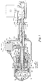
- the propeller system includes a hub 10 into which a plurality of propeller blades 20, of which only one is shown, are mounted. Each blade is mounted at its root end on bearings 12 in an socket 14 in the disc end of the hub 10 so as to be pivotably adjustable for pitch change about its longitudinal axis.
- the hub 10 has integral therewith a cylindrical housing 16 which extends axially and centrally forward of the disc portion of the hub 10.
- An eccentric roller 22 extends outwardly from the lower end of the root portion of the blade 20 and is received within a cam slot 24 of a desired shape provided in the blade actuation piston 30 in the rearward member 32 thereof which extends outwardly at the rearward end of longitudinally extending annular shaft 34 of the blade actuation piston 30.
- the bulkhead 40 of the piston 30 extends outwardly from the annular shaft 34 to the cylindrical hub housing 16 and provides a forward face 42 which is selectively pressurized with a fluid such as hydraulic oil in a manner to be described further hereinafter to cause the blade actuation piston 30 to move along its longitudinal axis in a rearward direction so as to impart coarse pitch, i.e. an increase in pitch, to the blade 20.
- a second annular piston 50 is disposed within the cylindrical hub housing 16 about the shaft 34 of the blade actuation piston 30.
- the second annular piston 50 also referred to herein as the pitchlock piston, has a forward face 52 which operates against the blade actuation piston 30 and a rearward face 54 which is selectively pressurized with fluid in a manner to be described further hereinafter to cause the pitchlock piston 50 to push against the blade actuation piston 30 to move the blade actuation piston 30 along its longitudinal axis in the forward direction so as to impart fine pitch to the blade 20.
- Bias spring means 60 is operatively disposed between the pitchlock piston 50 and the blade actuation piston 30 for exerting a preload force against the pitchlock piston 50 to bias the pitchlock piston 50 away from the blade actuation piston 30. In operation, when the fluid pressure exerted upon the rearward face 54 of the pitchlock piston 50 drops below the preload force and the pitchlock piston 50 backs away from and out of contact with the blade actuation piston 30.
- Hydraulic fluid is selectively passed into the cylindrical hub housing through an elongated conduit means 70 and directed against the either the blade actuation piston 30 or the pitchlock piston 50 to cause the movement necessary to change the pitch of the blades 20 to a desired setting.
- the conduit means 70 is operatively interconnected at its other end in fluid communication with a fluid supply control valve 100 which selectively meters hydraulic fluid from a supply pump (not shown) into either the coarse pitch passageway 72 or the fine pitch passageway 74 of the conduit means 70.
- the control valve means 100 advantageously comprises a conventional electrohydraulic four-way servoed beta valve of the type well-known in the art which selectively meters the hydraulic fluid from supply conduit 106 to either the coarse pitch passageway 72 or the fine pitch passageway 74 of the conduit means 70 through the coarse pitch conduit 102 or the fine pitch conduit 104, respectively.
- a conventional electrohydraulic four-way servoed beta valve of the type well-known in the art which selectively meters the hydraulic fluid from supply conduit 106 to either the coarse pitch passageway 72 or the fine pitch passageway 74 of the conduit means 70 through the coarse pitch conduit 102 or the fine pitch conduit 104, respectively.
- various control valves means of the electrohydraulic type or fluid mechanical type, or combinations thereof may be used with the pitch change actuator of the present invention.
- the bulkhead 40 of the blade actuation piston 30 extends outwardly from the forward end of the piston shaft 34 to the inner surface of the cylindrical hub housing 16 so as to form a first fluid chamber 36 within the housing 16 forward of the bulkhead 40 of the blade actuation piston 30.
- the annular pitchlock piston 50 is disposed about the blade actuation piston shaft 34 in spaced relationship therewith and just rearward of the blade actuation piston 30 so as to form an annular second fluid chamber 38 within the housing 16 rearward of the rearward face 54 of the pitchlock piston 50.
- the bias spring 60 is disposed in a cavity in the forward face 52 of the pitchlock piston 50 so as to operate between the rearward face 44 of the bulkhead 40 of the blade actuation piston 30 and the forward face 52 of the pitchlock piston 50.
- the conduit means 70 comprises a pair of coaxially disposed longitudinally extending tubular members 80 and 90 which pass axially through the interior of the longitudinally extending shaft 34 of the blade actuation piston 30.
- the inner tubular member 80 extends from the forward end of the cylindrical hub housing 16 rearwardly along the axis of and through the housing 16 and through the propeller gearbox 155 disposed aft of the hub housing 16, and defines a fine pitch fluid passageway 74 within its interior.
- the fine pitch fluid passageway 74 is connected at its forward end in fluid communication with the second fluid chamber 38 via conduit 18 in the wall of the hub housing 16 and is connected at its rearward end in fluid communication with the control valve 100 via conduit 104, channel 124 in oil bearing 120 disposed about the outer tubular member 90, and channels 114 which pass through both the wall of the outer tubular member 90 and that of the inner tubular member 80.
- the outer tubular member 90 is disposed about the inner tubular member 80 in spaced relationship therewith so as to define a coarse pitch fluid passageway 72 in the annular space formed therebetween.
- the coarse pitch fluid passageway 72 is connected at its outlet at its forward end directly in fluid communication with the first fluid chamber 36 and is connected at its rearward end in fluid communication with the control valve 100 via conduit 102, channel 122 in oil bearing 120 disposed about the outer tubular member 90, and ports 112 which pass through the wall of the outer tubular member 90.
- first annular screw member 130 operatively associated with the pitchlock piston 50
- second annular screw member 140 disposed on the outer surface of the shaft 34
- annular linking member 150 coaxially disposed about the shaft 34 between the first and second screw members.
- the pitchlock piston 50, the first annular screw member 130, the second annular screw member 140 and the intermediate annular linking member 150 function cooperatively to form a pitchlock mechanism which prevents the blades 20 from inadvertently going toward fine pitch.
- the first screw member advantageously comprises annular ballscrew means 130 rotatably mounted to an interior cylindrical extension 162 of the hub housing 16 via the ball race 132 of the ballscrew means 130 and coupled to the shaft 56 of the pitchlock piston 50 by means of bearing 134 so as to simultaneously translate with and rotate within the pitchlock piston 50.
- the ballscrew means 130 is operatively connected to the second screw member, which advantageously comprises acme screw 140 machined into the outer surface of the shaft 34, by the linking member 150 which comprises a cylindrical quill threaded at its forwarded end to the acme screw 140 and having spline means 152 on its outer surface which engage tab-like keys 136 depending from the ballscrew means.
- a pitchlock stop 154 extends outwardly from the rearward end of the quill 150 for engaging the inward extending flange 164 of the hub housing 16 so as to ground the pitchlock mechanism and prevent further movement of the blade actuation piston 34 toward fine pitch in the event of a hydraulic failure.
- hydraulic fluid is selectively passed from the fluid supply (not shown) into the first fluid chamber 36 via the control valve 100 through conduit 102, thence through channel 122 in oil bearing 120 and ports 112 into and through the annular coarse pitch fluid passageway 72 between the inner tubular member 80 and the outer tubular member 90.
- the resultant pressurization of the first fluid chamber 36 causes movement of the blade actuation piston 30 rearwardly (to the right in Figure 1) and a corresponding increase in pitch of the blades 20.
- the blade actuation piston 30 moves rearwardly, it also pushes the pitchlock piston 50 rearwardly with it and forces hydraulic fluid within the second fluid chamber 38 to drain therefrom under the control of the control valve 100 back to the fluid supply through conduit 18 and the fine pitch fluid passageway 74.
- the fluid pressure force exerted on the rearward face 54 of the pitchlock piston 50 decreases to an equilibrium valve at the new pitch setting.
- the coarse pitch pressure force acting to the right on the blade actuation piston 30 counter-balances the sum of the blade load and the net fine pitch pressure force on the pitchlock piston 50, both of which act to the left in Figure 1.
- the coarse pitch pressure and the fine pitch pressure must sum, at least approximately, to the supply pressure, and the coarse pitch pressure must adjust to counter changes in the blade load force, the fine pitch pressure will change accordingly.
- the fine pitch pressure could drop to near zero as the coarse pitch pressure increases to counter-balance an increase in blade load.
- the supply pressure would decrease as fluid leaks out of the system.
- the control valve 100 would shuttle in an attempt to maintain the pressure force exerted (to the right) on the blade actuation piston 30 and simultaneously reduce pressure to the second fluid chamber 38.
- the fine pitch flow will necessarily deteriorate rapidly.
- the coarse pitch pressure will follow and, if unchecked by a mechanical pitchlock mechanism, the blades will go to lower pitch and an inadvertent undesirable overspeed of the propeller system will occur.
- the ballscrew 130 When the pitchlock piston 50 is moving with the blade actuation piston 30 as in normal operation, the ballscrew 130 not only translates therewith but also rotates and causes the quill 150 keyed thereto to also rotate about the shaft 34 of the blade actuation piston 30. This rotation of the quill 150 causes the quill to move on the acme screw 140 to which it is threaded so as to maintain a desired pitchlock gap 166 between the pitchlock stop 154 extending outwardly from the rearward end of the quill 150 for engaging the inward extending flange 164 of the hub housing 16.
- the pitchlock piston 50 becomes disengaged from the blade actuation piston so as to no longer translate therewith. Consequently, the rotation of the ballscrew 130 also ceases. With the desired pitchlock gap 166 having been maintained, it is assured that the pitchlock stop 154 will quickly ground and prevent any inadvertent fine pitch change even if the blade load overcomes the coarse pitch pressure force such as would occur in the event of the loss of supply pressure.
- the bulkhead 40 of the blade actuation piston 30 extends outwardly from an intermediate location on the piston shaft 34 to the inner surface of the cylindrical rearwardly extending flange 216 of hub housing 16 so as to from a first fluid chamber 36 within the housing 16 forward of the bulkhead 40 of the blade actuation piston 30.
- the annular pitchlock piston 50 is disposed about the blade actuation piston shaft 34 in spaced relationship therewith and forward of the blade actuation piston 30 so as to form an annular second fluid chamber 38 within the housing 16 rearward of the rearward face 54 of the pitchlock piston 50.
- the bias spring 60 is disposed between the forward face 52 of the pitchlock piston 50 and an annular flange 234 extending outwardly from the shaft 34 forward of the pitchlock piston 50 so as to operate between the rearward face 244 of the annular flange 234 of the blade actuation piston 30 and the forward face 54 of the pitchlock piston 50.
- the conduit means 70 comprises a longitudinally extending cylindrical rod-like member 280 which extends axially into the interior of the longitudinally extending shaft 34 of the blade actuation piston 30.
- the member 280 extends from the second fluid chamber 38 of the cylindrical hub housing 16 rearwardly along the axis of and through the housing 16 and through the propeller gearbox 155 disposed aft of the hub housing 16.
- a coarse pitch fluid passageway 72 and a fine pitch fluid passageway 74 are formed within its interior.
- the coarse pitch fluid passageway 72 is connected at at its forward end in fluid communication with the first fluid chamber 36 via channel 236 and is connected at its rearward end in fluid communication with the control valve 100 via conduit 102, channel 222 in oil bearing 220 disposed about the member 280, and port 212.
- the fine pitch fluid passageway 74 is connected at its forward end in fluid communication with the second fluid chamber 38 via port 218 and is connected at its rearward end in fluid communication with the control valve 100 via conduit 104, channel 274 in oil bearing 270 disposed about the member 280, and channel 214.
- first annular screw member 230 operatively associated with the pitchlock piston 50
- second annular screw member 240 disposed on the outer surface of the shaft 34
- annular linking member 250 coaxially disposed about the shaft 34 between the first and second screw members.
- the pitchlock piston 50, the first annular screw member 230, the second annular screw member 240 and the intermediate annular linking member 250 function cooperatively to form a pitchlock mechanism which prevents the blades 20 from inadvertently going toward fine pitch.
- the first screw member advantageously comprises annular ballscrew means 230 rotatably mounted to the hub housing 16 by means of bearing 284 and coupled to the inner wall of the annular shaft 256 of the pitchlock piston 50 via the ball race 232 of the ballscrew means 230 so as to simultaneously translate with and rotate within the pitchlock piston 50.
- the ballscrew means 230 is operatively connected to the second screw member, which advantageously comprises acme screw 240 machined into the outer surface of the forward end of the shaft 34, by the linking member 250 which comprises a cylindrical quill threaded at its rearward end to the acme screw 240 and having spline means 252 on its outer surface which engage tab-like keys 238 depending from the ballscrew means.
- the forward-most end of the quill 250 serves as a pitchlock for engaging the inner wall of the forward end of the hub housing 16 so as to ground the pitchlock mechanism and prevent further movement of the blade actuation piston 34 toward fine pitch in the event of a hydraulic failure.
- hydraulic fluid is selectively passed from the fluid supply (not shown) into the first fluid chamber 36 via the control valve 100 through conduit 102, thence through channel 222 in oil bearing 220 and port 212 into and through the coarse pitch fluid passageway 72 and the channel 236 at the forward end thereof.
- the resultant pressurization of the first fluid chamber 36 generates a pressure force against the forward face of the bulkhead 40 which causes movement of the blade actuation piston 30 rearwardly (to the right in Figure 2) and a corresponding increase in pitch of the blades 20.
- the coarse pitch pressure force acting to the right on the forward face of the bulkhead 40 of the blade actuation piston 30 counter-balances the sum of the blade load and the net fine pitch pressure force on the pitchlock piston 50, both of which act to the left in Figure 1.
- the coarse pitch pressure and the fine pitch pressure must sum, at least approximately, to the supply pressure, and the coarse pitch pressure must adjust to counter changes in the blade load force, the fine pitch pressure will change accordingly.
- the fine pitch pressure could drop to near zero as the coarse pitch pressure increases to counter-balance an increase in blade load.
- the supply pressure would decrease as fluid leaks out of the system.
- the control valve 100 would shuttle in an attempt to maintain the pressure force exerted (to the right) on the forward face of the bulkhead 40 of the blade actuation piston 30 and simultaneously reduce pressure to the second fluid chamber 38.
- the fine pitch flow will necessarily deteriorate rapidly.
- the coarse pitch pressure will follow and, if unchecked by a mechanical pitchlock mechanism, the blades will go to lower pitch and an inadvertent undesirable overspeed of the propeller system will occur.
- the ballscrew 230 When the pitchlock piston 50 is moving with the blade actuation piston 30 as in normal operation, the ballscrew 230 not only translates therewith but also rotates and causes the quill 250 keyed thereto to also rotate about the shaft 34 of the blade actuation piston 30. This rotation of the quill 250 causes the quill to move on the acme screw 240 to which it is threaded so as to maintain a desired pitchlock gap 266 between the forward-most end of the quill 250 for engaging the inner wall of the forward end of the hub housing 16.
- the pitchlock piston 50 becomes disengaged from the blade actuation piston so as to no longer translate therewith. Therefore, the rotation of the ballscrew 230 also ceases. With the desired pitchlock gap 166 having been maintained, it is assured that the forward end of the quill 250 will quickly ground and prevent any inadvertent fine pitch change in the event of the loss of supply pressure.
Landscapes
- Engineering & Computer Science (AREA)
- Aviation & Aerospace Engineering (AREA)
- Actuator (AREA)
Claims (4)
- Blattverstellstellantrieb für ein Blattverstellbetätigungssystem zum Einstellen des Einstellwinkels eines Verstellpropellerblattes, das an einer Nabe des Propellers drehbar gelagert ist, wobei der Blattverstellstellantrieb in Wirkverbindung mit dem Propellerblatt (20) steht und wobei eine Steuerventileinrichtung in Wirkverbindung mit dem Blattverstellstellantrieb steht, um den Blattverstellstellantrieb wahlweise mit Druck zu beaufschlagen und eine gewünschte Änderung des Einstellwinkels des Propellerblattes hervorzurufen, wobei der Blattverstellstellantrieb aufweist:a. einen ringförmigen Blattbetätigungskolben (30), der mit dem Propellerblatt (20) in Wirkverbindung steht, wodurch eine Längsbewegung des Blattbetätigungskolbens eine Drehung des Propellerblattes bewirkt, wodurch sich eine Änderung des Einstellwinkels des Propellerblattes ergibt, und wobei der Blattbetätigungskolben ein sich nach außen erstreckendes Kopfteil (40) und eine sich von diesem aus in Längsrichtung erstreckende ringförmige Welle (34) hat, die mit einem Ende des Propellerblattes in Wirkverbindung steht;b. einen zweiten ringförmigen Kolben (50), der ein ringförmiges Kopfteil (52, 54) und eine sich von ihm aus erstreckende, in Längsrichtung gerichtete ringförmige Welle (56, 256) hat, welche mit Abstand um die Welle (34) des Blattbetätigungskolbens (30) angeordnet ist;c. eine Federeinrichtung (60), die wirkungsmäßig zwischen dem zweiten Kolben (50) und dem Blattbetätigungskolben (30) angeordnet ist, um eine Vorbelastungskraft auf den zweiten Kolben auszuüben, so daß der zweite Kolben weg von dem Blattbetätigungskolben vorgespannt wird, bis die Vorbelastungskraft überwunden wird;d. eine Einstellwinkelverriegelungseinrichtung (130, 140, 150, 230, 240, 256), die wirkungsmäßig zwischen den zweiten Kolben (50) und den Blattbetätigungskolben (30) geschaltet ist, um eine ungewollte Blatteinstellwinkelverringerung zu verhindern.e. eine Leitungseinrichtung (70), die in Wirk- und Fluidverbindung zwischen die Steuerventileinrichtung (100) und den Blattverstellstellantrieb geschaltet ist, um wahlweise ein Druckfluid zwischen die Steuerventileinrichtung (100) und den Blattbetätigungskolben (30) zu leiten und dadurch eine erste Druckkraft an dem Blattbetätigungskolben (30) zu erzeugen, und zwischen die Steuerventileinrichtung (100) und den zweiten Kolben (50), um dadurch eine zweite Druckkraft an dem zweiten Kolben (50) zu erzeugen.
- Blattverstellstellantrieb nach Anspruch 1, wobei die Leitungseinrichtung (70), die in Wirk- und Fluidverbindung zwischen die Steuerventileinrichtung und den Blattverstellstellantrieb geschaltet ist, ein axial langgestrecktes, stangenartiges Teil (80, 90, 280) aufweist, das so angeordnet ist, daß es longitudinal durch das Innere der Welle (34) des Blattbetätigungskolbens (30) hindurchgeht, und in dem ein erster, longitudinal gerichteter Durchlaß vorgesehen ist, um das Druckfluid zwischen die Steuerventileinrichtung (100) und den Blattbetätigungskolben (30) zu leiten, und in dem ein zweiter, longitudinal gerichteter Durchlaß vorgesehen ist, um das Druckfluid zwischen die Steuerventileinrichtung und den zweiten Kolben zu leiten.
- Blattverstellstellantrieb nach Anspruch 1, wobei die Leitungseinrichtung, die in Wirk- und Fluidverbindung zwischen die Steuerventileinrichtung und den Blattverstellstellantrieb geschaltet ist, ein erstes, axial langgestrecktes, rohrförmiges Teil (80) aufweist, das so angeordnet ist, daß es longitudinal durch das Innere des Blattverstellstellantriebskolbens hindurchführt, und ein zweites, axial langgestrecktes, rohrförmiges Teil (80), das koaxial mit Abstand innerhalb des ersten rohrförmigen Teils angeordnet ist und sich longitudinal durch dieses erstreckt, um dadurch einen ringförmigen ersten, longitudinal gerichteten Strömungsdurchlaß (72) zwischen dem ersten und zweiten rohrförmigen Teil zu bilden, um das Druckfluid zwischen die Steuerventileinrichtung und den Blattbetätigungskolben zu leiten, und um einen zweiten, longitudinal gerichteten Strömungsdurchlaß (74) innerhalb des zweiten rohrförmigen Teils zu bilden, um das Druckfluid zwischen die Steuerventileinrichtung und den zweiten Kolben zu leiten.
- Blattverstellstellantrieb nach Anspruch 1, wobei die Einstellwinkelverriegelungseinrichtung aufweist:a. ein erstes ringförmiges Schraubteil (130, 230), das dem zweiten Kolben wirkungsmäßig zugeordnet ist, wodurch eine Längsverschiebung des zweiten Kolbens eine entsprechende Drehung des ersten Schraubteils bewirkt;b. ein zweites ringförmiges Schraubteil (140, 240), das auf der Welle des Blattbetätigungskolbens angeordnet ist;c. ein ringförmiges Verbindungsteil (150, 250), das koaxial um die Welle des Blattbetätigungskolbens zwischen dem ersten und zweiten Schraubteil angeordnet ist, wobei das Verbindungsteil ein erstes Ende aufgeschraubt auf das zweite Schraubteil hat, das auf der Welle des Blattbetätigungskolbens angeordnet ist, und ein zweites Ende verbunden mit dem ersten Schraubteil, wodurch sich das Verbindungsteil mit dem ersten Schraubteil dreht, so daß es sich longitudinal längs des zweiten Schraubteils verschiebt, undd. eine Anschlageinrichtung integral mit (154) dem Verbindungsteil zum Verhindern einer weiteren longitudinalen Verschiebung des Blattbetätigungskolbens in der Richtung eines Feineinstellwinkels immer dann, wenn die zweite Druckkraft nicht ausreicht, um die Vorbelastungskraft zu überwinden.
Applications Claiming Priority (1)
| Application Number | Priority Date | Filing Date | Title |
|---|---|---|---|
| US07/600,644 US5141399A (en) | 1990-10-18 | 1990-10-18 | Pitch change control system |
Publications (2)
| Publication Number | Publication Date |
|---|---|
| EP0559990A1 EP0559990A1 (de) | 1993-09-15 |
| EP0559990B1 true EP0559990B1 (de) | 1995-09-06 |
Family
ID=24404472
Family Applications (1)
| Application Number | Title | Priority Date | Filing Date |
|---|---|---|---|
| EP92630032A Expired - Lifetime EP0559990B1 (de) | 1990-10-18 | 1992-03-13 | Steuersystem der Blatteinstellwinkelverstelleinrichtung |
Country Status (2)
| Country | Link |
|---|---|
| US (1) | US5141399A (de) |
| EP (1) | EP0559990B1 (de) |
Families Citing this family (21)
| Publication number | Priority date | Publication date | Assignee | Title |
|---|---|---|---|---|
| US5186608A (en) * | 1991-10-25 | 1993-02-16 | United Technologies Corporation | Hydraulic low pitch switch for propeller pitch change system |
| US5391055A (en) * | 1993-11-24 | 1995-02-21 | United Technologies Corporation | Propeller pitch change mechanism with impulse turbines |
| US5685694A (en) * | 1995-11-07 | 1997-11-11 | Sundstrand Corporation | Air driven turbine having a blade pitch changing mechanism including overspeed protection |
| RU2099241C1 (ru) * | 1996-10-17 | 1997-12-20 | Йелстаун Корпорейшн Н.В. | Система управления флюгерно-реверсивным воздушным винтом для самолетов местных авиалиний |
| RU2101212C1 (ru) * | 1996-10-17 | 1998-01-10 | Йелстаун Корпорейшн Н.В. | Система управления соосным реверсивным винтовентилятором |
| US5836743A (en) * | 1997-10-22 | 1998-11-17 | United Technologies Corporation | Variable pitch counterweighted propeller system with releasable hydraulic pitchlock |
| US6077040A (en) * | 1998-05-01 | 2000-06-20 | United Technologies Corporation | Control system for blades for a variable pitch propeller |
| US6389719B1 (en) | 2000-05-16 | 2002-05-21 | Robotic Displays Corporation | Display device |
| US7118336B2 (en) * | 2003-12-19 | 2006-10-10 | Pratt & Whitney Canada Corp. | Pressurized oil supply for propeller engine system |
| US8267656B2 (en) * | 2006-03-08 | 2012-09-18 | Hamilton Sundstrand Corporation | Propeller pitch lock system |
| US8545178B2 (en) * | 2006-03-08 | 2013-10-01 | Hamilton Sundstrand Corporation | Controlled propeller pitch lock actuation system |
| EP2050670A3 (de) * | 2008-01-11 | 2011-11-23 | MT-Propeller Entwicklung GmbH | Elektro-Hydraulischer Propellerregler |
| US8277182B2 (en) * | 2009-07-02 | 2012-10-02 | Hamilton Sundstrand Corporation | Remote pitch controller for a variable pitch propeller |
| FR3037922B1 (fr) * | 2015-06-23 | 2017-07-07 | Turbomeca | Dispositif de regulation d'une helice a pales a calage variable d'un turbopropulseur |
| JP6285500B2 (ja) * | 2015-07-08 | 2018-02-28 | ジーイー・アビエイション・システムズ・エルエルシー | ピッチ制御組立体及びプロペラ組立体並びにピッチを調整する方法 |
| US10393137B2 (en) | 2016-02-12 | 2019-08-27 | General Electric Company | Method and system for integrated pitch control mechanism actuator hydraulic fluid transfer |
| FR3048953B1 (fr) * | 2016-03-21 | 2018-04-06 | Arianegroup Sas | Helice d'aeronef comprenant des pales pliables et a calage variable |
| EP3431390B1 (de) * | 2017-07-17 | 2022-08-31 | Ratier-Figeac SAS | Hydraulischer aktuator |
| FR3072714B1 (fr) * | 2017-10-24 | 2019-09-27 | Safran Transmission Systems | Tube de transfert d'huile pour un systeme de commande de regulation du pas d'une helice de turbomachine |
| FR3141443B1 (fr) * | 2022-10-28 | 2025-04-04 | Safran Aircraft Engines | Mécanisme de changement de pas avec vérin de commande et dispositif de verrouillage de pas hors des chambres du vérin |
| FR3141442B1 (fr) * | 2022-10-28 | 2025-03-07 | Safran Aircraft Engines | Mécanisme de changement de pas avec dispositif de verrouillage de pas en porte-à-faux |
Family Cites Families (4)
| Publication number | Priority date | Publication date | Assignee | Title |
|---|---|---|---|---|
| US2501720A (en) * | 1943-12-24 | 1950-03-28 | Rotol Ltd | Screw propeller |
| DK111869B (da) * | 1961-10-26 | 1968-10-14 | N Liaaen | Servomekanisme til drejning af bladene i en skibspropel. |
| FR1395753A (fr) * | 1964-03-05 | 1965-04-16 | Ratier Figeac Soc | Système de sécurité pour vérins hydrauliques et son application aux hélices à pas variable |
| US4365937A (en) * | 1979-11-26 | 1982-12-28 | Hiebert Harold L | Adjustable pitch propeller drive |
-
1990
- 1990-10-18 US US07/600,644 patent/US5141399A/en not_active Expired - Lifetime
-
1992
- 1992-03-13 EP EP92630032A patent/EP0559990B1/de not_active Expired - Lifetime
Also Published As
| Publication number | Publication date |
|---|---|
| US5141399A (en) | 1992-08-25 |
| EP0559990A1 (de) | 1993-09-15 |
Similar Documents
| Publication | Publication Date | Title |
|---|---|---|
| EP0559990B1 (de) | Steuersystem der Blatteinstellwinkelverstelleinrichtung | |
| EP0598067B1 (de) | Blattwinkelverstellsteuerung | |
| US5186608A (en) | Hydraulic low pitch switch for propeller pitch change system | |
| US4523891A (en) | Propeller pitch change actuation system | |
| US5836743A (en) | Variable pitch counterweighted propeller system with releasable hydraulic pitchlock | |
| US4097189A (en) | Aircraft propeller and blade pitch control system | |
| EP1073583B1 (de) | Steuerungssystem für die blätter eines propellers mit verstellbaren anstellwinkel | |
| US6811376B2 (en) | Actuation system for a controllable pitch propeller | |
| US4037986A (en) | Bladed rotors having control means for effecting blade pitch adjustment | |
| US6261062B1 (en) | Actuation system for a controllable pitch propeller | |
| GB2260821A (en) | LVDT for propeller pitch change system | |
| US4588354A (en) | Engine speed control in propeller pitch control systems | |
| US3212586A (en) | Pitch control system | |
| EP0112793B1 (de) | Blatteinstellwinkelsteuerungssystem für eine verstellbare Luftschraube | |
| US3459267A (en) | Bladed rotors | |
| US20250051004A1 (en) | Hydraulic control circuit for controlling fan blade pitch | |
| US4893989A (en) | Variable propeller system incorporating a forward transfer bearing | |
| US2462932A (en) | Pitch changing mechanism | |
| US4822243A (en) | Bladed rotor assemblies and control means therefor | |
| US3240275A (en) | Hydraulically operable pitch aircraft propeller | |
| US2382389A (en) | Propeller mechanism | |
| US20250084836A1 (en) | Hydraulic control circuit for controlling fan blade pitch | |
| US3027949A (en) | Adjustable pitch propeller having integral control system | |
| US2704583A (en) | Adjustable hydraulic reverse stop | |
| US3672242A (en) | Crank with adjustable crank radius |
Legal Events
| Date | Code | Title | Description |
|---|---|---|---|
| PUAI | Public reference made under article 153(3) epc to a published international application that has entered the european phase |
Free format text: ORIGINAL CODE: 0009012 |
|
| AK | Designated contracting states |
Kind code of ref document: A1 Designated state(s): FR GB IT |
|
| 17P | Request for examination filed |
Effective date: 19940207 |
|
| 17Q | First examination report despatched |
Effective date: 19941115 |
|
| GRAA | (expected) grant |
Free format text: ORIGINAL CODE: 0009210 |
|
| AK | Designated contracting states |
Kind code of ref document: B1 Designated state(s): FR GB IT |
|
| ET | Fr: translation filed | ||
| ITF | It: translation for a ep patent filed | ||
| PG25 | Lapsed in a contracting state [announced via postgrant information from national office to epo] |
Ref country code: GB Effective date: 19960313 |
|
| PLBE | No opposition filed within time limit |
Free format text: ORIGINAL CODE: 0009261 |
|
| 26N | No opposition filed | ||
| GBPC | Gb: european patent ceased through non-payment of renewal fee |
Effective date: 19960313 |
|
| PG25 | Lapsed in a contracting state [announced via postgrant information from national office to epo] |
Ref country code: FR Effective date: 19961129 |
|
| REG | Reference to a national code |
Ref country code: FR Ref legal event code: ST |
|
| PG25 | Lapsed in a contracting state [announced via postgrant information from national office to epo] |
Ref country code: IT Free format text: LAPSE BECAUSE OF NON-PAYMENT OF DUE FEES;WARNING: LAPSES OF ITALIAN PATENTS WITH EFFECTIVE DATE BEFORE 2007 MAY HAVE OCCURRED AT ANY TIME BEFORE 2007. THE CORRECT EFFECTIVE DATE MAY BE DIFFERENT FROM THE ONE RECORDED. Effective date: 20050313 |