EP0560076A1 - Ensemble de guidage pour le coulissement d'un tiroir - Google Patents
Ensemble de guidage pour le coulissement d'un tiroir Download PDFInfo
- Publication number
- EP0560076A1 EP0560076A1 EP93102205A EP93102205A EP0560076A1 EP 0560076 A1 EP0560076 A1 EP 0560076A1 EP 93102205 A EP93102205 A EP 93102205A EP 93102205 A EP93102205 A EP 93102205A EP 0560076 A1 EP0560076 A1 EP 0560076A1
- Authority
- EP
- European Patent Office
- Prior art keywords
- pull
- rail
- support
- rails
- mounting
- Prior art date
- Legal status (The legal status is an assumption and is not a legal conclusion. Google has not performed a legal analysis and makes no representation as to the accuracy of the status listed.)
- Granted
Links
- 230000008878 coupling Effects 0.000 claims abstract description 3
- 238000010168 coupling process Methods 0.000 claims abstract description 3
- 238000005859 coupling reaction Methods 0.000 claims abstract description 3
- 230000000284 resting effect Effects 0.000 abstract 1
- 230000000717 retained effect Effects 0.000 abstract 1
- 230000006835 compression Effects 0.000 description 3
- 238000007906 compression Methods 0.000 description 3
- 238000010586 diagram Methods 0.000 description 2
- 238000004519 manufacturing process Methods 0.000 description 2
- 238000004026 adhesive bonding Methods 0.000 description 1
- 238000006073 displacement reaction Methods 0.000 description 1
- 238000004080 punching Methods 0.000 description 1
Images
Classifications
-
- A—HUMAN NECESSITIES
- A47—FURNITURE; DOMESTIC ARTICLES OR APPLIANCES; COFFEE MILLS; SPICE MILLS; SUCTION CLEANERS IN GENERAL
- A47B—TABLES; DESKS; OFFICE FURNITURE; CABINETS; DRAWERS; GENERAL DETAILS OF FURNITURE
- A47B88/00—Drawers for tables, cabinets or like furniture; Guides for drawers
- A47B88/40—Sliding drawers; Slides or guides therefor
- A47B88/423—Fastening devices for slides or guides
- A47B88/43—Fastening devices for slides or guides at cabinet side
-
- A—HUMAN NECESSITIES
- A47—FURNITURE; DOMESTIC ARTICLES OR APPLIANCES; COFFEE MILLS; SPICE MILLS; SUCTION CLEANERS IN GENERAL
- A47B—TABLES; DESKS; OFFICE FURNITURE; CABINETS; DRAWERS; GENERAL DETAILS OF FURNITURE
- A47B2210/00—General construction of drawers, guides and guide devices
- A47B2210/0002—Guide construction for drawers
- A47B2210/0029—Guide bearing means
- A47B2210/0032—Balls
-
- A—HUMAN NECESSITIES
- A47—FURNITURE; DOMESTIC ARTICLES OR APPLIANCES; COFFEE MILLS; SPICE MILLS; SUCTION CLEANERS IN GENERAL
- A47B—TABLES; DESKS; OFFICE FURNITURE; CABINETS; DRAWERS; GENERAL DETAILS OF FURNITURE
- A47B2210/00—General construction of drawers, guides and guide devices
- A47B2210/0002—Guide construction for drawers
- A47B2210/0051—Guide position
- A47B2210/0059—Guide located at the side of the drawer
Definitions
- the invention relates to a pull-out guide for drawers, each with a drawer-side pull-out rail and a body-side mounting rail on each side of the drawer and preferably one each arranged between the pull-out rail and the mounting rail, the mounting rails by means of coupling parts on mounting brackets, which in turn support the Body side walls are mounted and hooks are formed on the support brackets at the rear, under which support rails can be inserted, being held in the pushed-in position by rocker arms which are rotatably mounted on the support rails and bear against a locking edge of the support bracket.
- the rails of the pull-out guide sets In general, it is common for the rails of the pull-out guide sets to be attached to the cabinet side walls and the pull-out rails to be attached to the drawers when producing a piece of furniture.
- the rails of the pull-out guide assembly cannot be pulled apart during operation, so that it is not possible to separate the rails for assembly.
- the furniture parts in particular the side walls, are easy to stack and pack. This presupposes that no or only slightly protruding parts are mounted on the side walls of the furniture.
- a pull-out guide set for drawers is known, in which the mounting rail is attached to a mounting bracket attached to the side wall of the furniture.
- a disadvantage of the known pull-out guide set is that, due to inaccurate manufacture, excessive play can occur between the mounting rails and the mounting brackets, which questions the fit and the smooth running of the drawer. Furthermore, the drawer is not secured against lifting off the support brackets.
- the US-PS 4,423,914 shows a pull-out guide set, in which the pull-out rails are anchored to the bracket of the drawer.
- the pull-out rails are secured against shifting in their longitudinal direction by rocker arms.
- the pull-out guide set cannot be pre-assembled on the drawer before the furniture is assembled.
- the object of the invention is to improve a pull-out guide set so that the mounting rails, which are anchored to the drawers via the pull-out rails before the drawer is anchored in the furniture, are held firmly on the mounting brackets even with customary manufacturing tolerances.
- the pull-out guide set according to the invention is particularly suitable for full extensions, i.e. H. Excerpts in which a so-called central rail is arranged between the mounting rail and the pull-out rail.
- the object of the invention is achieved in that the rocker arms, which are acted upon by a spring, are mounted in a housing fastened to or in the mounting rail and in that horizontally displaceable balls or a locking bolt acted upon by a spring in the housing are arranged, which snap into the grooves formed on the support bracket or the like.
- the rocker arm is advantageously provided with steps that rest against the locking edge, which means that assembly tolerances can be better compensated for.
- the drawer can be torn up with the mounting rails and thus released from the mounting brackets without damaging the locking mechanism.
- the drawer with the pull-out guide sets is placed on the mounting brackets and pushed backwards until the rear ends of the mounting rails engage under the hooks of the mounting brackets. As soon as the rocker arm is behind the locking edge, it is moved into the rocking position by the spring and engages. The mounting rails are therefore secured against axial displacement.
- Both a spiral spring and a compression spring can be used to act on the rocker arm.
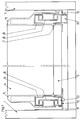
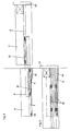
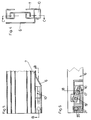
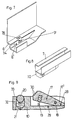
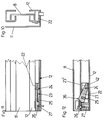
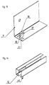
- FIG. 1 shows a cross section through a drawer, with a different embodiment of the pull-out guide assembly according to the invention on each side of the drawer is shown; 2 shows a side view of a drawer and a pull-out guide set in the pulled-out state of the drawer; 3 shows a similar side view in the inserted position of the drawer; FIG. 4 shows a cross section through one side of a pull-out guide set according to the right embodiment of FIG. 1; Fig. 5 shows a section along the line CC of Fig. 4; Fig. 6 shows a section along the line BB of Fig. 5; FIG. 7 shows a diagram of the front end of a mounting bracket, FIG. 8 shows a diagram of the front end of the mounting rail, FIG. 9 shows a horizontal section through a locking device and FIGS. 10 to 14 show analogous views of FIG. 4 to 8 according to the left embodiment of FIG. 1st
- Each pull-out guide set consists of the pull-out rail 9, the middle rail 8 and the body rail 7 or 12.
- Carriages 15 are mounted between the support rails 7, 12 and the middle rails 8 and the pull-out rails 9.
- the carriages 15 are manufactured according to the conventional state of the art and are not shown in detail in the figures of the drawings.
- the rails 7, 8, 9, 11 are inserted into the drawer side walls 5, while the support brackets 6, 11 are fastened to the body side walls 1.
- the drawer base is denoted by 3, the drawer rear wall by 4 and the front panel of the drawer by the reference number 13.
- FIG. 1 The right embodiment of FIG. 1 is described below with reference to FIGS. 4 to 9.
- a housing 10 is fastened at the front end.
- the attachment can be done by screwing, riveting or gluing.
- the rocker arm 17, which is rotatable about a vertical axis 18, is mounted in the housing 10.
- the rocker arm 17 is acted upon by a spring 19 and has a stop 28 on the rear lever arm 17 ′, which abuts the housing wall 29 and prevents the rocker arm 17 from projecting too far.
- the front of the rocker arm 17 is provided with steps 30 which rest in the mounting position on the locking edge 31 of the support bracket 6. 6 shows the rocker arm 17 in its locked position.
- a cylindrical opening 32 in which a ball 20 is mounted.
- the ball 20 is acted upon by a helical spring 21 and pressed outwards.
- the cylindrical opening 32 has at the front, i. H. on the release side of the rocker arm 17 has a taper 33 so that the ball 20 cannot fall out of the housing 10.
- the ball 20 engages in the mounting position in a groove 34 in the support bracket 6.
- the support bracket 6 is provided with a hook 16 at the rear.
- the drawer with the support rails 7 is placed on the support brackets 6. Then the drawer with the support rails 7 is pushed backwards until the rear ends of the horizontal webs of the support rails 7 are pushed under the hooks 16. In this situation, the rocker arm 17 is located next to the punching 35 in the side web 6 'of the support bracket 6 and is pressed by the coil spring 20 into the punch 35, so that it rests with a step 30 on the locking edge 31 of the recess 35. The support rails 7 are thus secured to the support bracket 6 in the axial direction. The strength of the spring 19 is sufficient to prevent the carrier rails 7 from being moved unintentionally. Because of the balls 20, which are pressed into the grooves 34 by the springs 21, the mounting rails 7 cannot be lifted off the mounting brackets 6 either.
- the mounting rails 7 are to be lifted off the mounting brackets 6, the mounting rails 7 are pressed upwards until the pressure of the compression spring 21 is overcome. So that the front ends of the mounting rails 7 are released.
- FIG. 1 In the left embodiment of FIG. 1, which is shown in more detail in FIGS. 10 to 14, the housing 22 is mounted directly in the mounting rail 12.
- a rocker arm 23 in turn is supported in the housing 22 on an axis 24, which is acted upon by a helical spring 25.
- the rocker arm 23 in turn has steps 36.
- the assembly of the pull-out guide sets on the support brackets 11 is carried out analogously to the previously described embodiment.
- the support rails 12 are placed on the horizontal webs of the support bracket 11 and pushed back until the rear ends come to rest under the hook 16.
- the rocker arm 23 is located directly in front of the latching edge 37, which is formed from a tab 38 punched out of the horizontal web of the support bracket 11.
- the tab 38 also has a groove 39.
- the housing 22 there is a bolt 26 with a conical tip instead of the ball 20.
- the bolt 26 is in turn acted upon by a compression spring 27 and to the outside, i. H. to the tab 38 and pressed into the groove 39 (with the mounting rail 12 installed).
- a downward-pointing tab 40 which, when the mounting rail 12 is mounted, projects into a punched-out portion 41 in the horizontal web of the mounting bracket 11.
- the bolt 26 in turn offers protection against unwanted lifting of the mounting rails 12 from the mounting brackets 11.
- the support rails 12 are pressed upward against the force of the springs 27 until the front ends of the support rails 12 are released. This is done without damaging the locking device formed by the bolts 26, the springs 27 and the groove 39.
- the rocker arm is designed as a two-armed lever and has a stop surface 42 on its rear lever arm 23 ′, which prevents the rocker arm 23 from being excessively released when the mounting rail 12 is not mounted.
Landscapes
- Drawers Of Furniture (AREA)
- Paper (AREA)
- Laser Surgery Devices (AREA)
- Semiconductor Lasers (AREA)
- Platform Screen Doors And Railroad Systems (AREA)
Applications Claiming Priority (2)
| Application Number | Priority Date | Filing Date | Title |
|---|---|---|---|
| AT0047492A AT399640B (de) | 1992-03-11 | 1992-03-11 | Ausziehführungsgarnitur für schubladen |
| AT474/92 | 1992-03-11 |
Publications (2)
| Publication Number | Publication Date |
|---|---|
| EP0560076A1 true EP0560076A1 (fr) | 1993-09-15 |
| EP0560076B1 EP0560076B1 (fr) | 1996-07-10 |
Family
ID=3491580
Family Applications (1)
| Application Number | Title | Priority Date | Filing Date |
|---|---|---|---|
| EP93102205A Expired - Lifetime EP0560076B1 (fr) | 1992-03-11 | 1993-02-12 | Ensemble de guidage pour le coulissement d'un tiroir |
Country Status (6)
| Country | Link |
|---|---|
| US (1) | US5292198A (fr) |
| EP (1) | EP0560076B1 (fr) |
| JP (1) | JP2569551Y2 (fr) |
| AT (2) | AT399640B (fr) |
| DE (1) | DE59303166D1 (fr) |
| ES (1) | ES2089602T3 (fr) |
Cited By (5)
| Publication number | Priority date | Publication date | Assignee | Title |
|---|---|---|---|---|
| US5570941A (en) * | 1994-02-25 | 1996-11-05 | Julius Blum Gesellschaft M.B.H. | Supporting rail fitting or assembly for drawer |
| AT408058B (de) * | 1997-06-27 | 2001-08-27 | Fulterer Gmbh | Ausziehvorrichtung für hochschränke |
| WO2006087048A1 (fr) * | 2005-02-16 | 2006-08-24 | Lautenschlaeger Horst | Dispositif destine a recevoir un tiroir |
| WO2013110598A1 (fr) * | 2012-01-27 | 2013-08-01 | Paul Hettich Gmbh & Co. Kg | Rail de guidage d'une coulisse |
| WO2017202048A1 (fr) * | 2016-05-25 | 2017-11-30 | 青岛海尔股份有限公司 | Mécanisme de rail coulissant et réfrigérateur en étant équipé |
Families Citing this family (32)
| Publication number | Priority date | Publication date | Assignee | Title |
|---|---|---|---|---|
| AT401717B (de) * | 1993-06-23 | 1996-11-25 | Blum Gmbh Julius | Schliessvorrichtung für schubladen |
| US5542759A (en) * | 1995-04-27 | 1996-08-06 | Snap-On Technologies, Inc. | Shock absorbing disconnect latch for drawer slides |
| US5671988A (en) * | 1995-05-24 | 1997-09-30 | Waterloo Furniture Components, Ltd. | Drawer slide latch |
| US5769517A (en) * | 1996-02-14 | 1998-06-23 | Carde; Felix | Drawer safety lock |
| ATA34396A (de) * | 1996-02-26 | 1998-10-15 | Blum Gmbh Julius | Ausziehführungsgarnitur für schubladen |
| DE19944640A1 (de) * | 1999-09-17 | 2001-03-22 | Hettich Paul Gmbh & Co | Ausziehführungsgarnitur |
| US6209979B1 (en) | 2000-02-22 | 2001-04-03 | General Devices Co., Ltd. | Telescoping slide with quick-mount system |
| US6749275B2 (en) * | 2002-06-21 | 2004-06-15 | General Devices Co., Inc. | Quick-mount support system for telescoping slide |
| WO2004000078A1 (fr) * | 2002-06-21 | 2003-12-31 | General Devices Co., Inc. | Systeme de support a montage rapide pour broche telescopique |
| US6601933B1 (en) | 2002-06-21 | 2003-08-05 | General Devices Co., Inc. | Telescoping slide with quick-mount system |
| WO2004016131A2 (fr) * | 2002-08-15 | 2004-02-26 | General Devices Co., Inc. | Ensemble coulissant |
| US7604307B2 (en) * | 2003-10-24 | 2009-10-20 | General Devices Co., Inc. | Telescoping slide assembly with quick-mount keyhole lock system |
| US6929339B1 (en) * | 2004-02-26 | 2005-08-16 | General Devices Co., Inc. | Latch controller for quick-mount support for telescoping slide |
| US6935711B1 (en) | 2004-02-26 | 2005-08-30 | General Devices Co., Inc. | Latch mover for quick-mount support for telescoping slide |
| US6957878B2 (en) * | 2004-02-26 | 2005-10-25 | General Devices Co., Inc. | Latch mover for quick-mount telescoping slide support system |
| EP1742556A1 (fr) * | 2004-05-07 | 2007-01-17 | Sca Hygiene Products Ab | Appareil de distribution en serie de produits en feuilles pliees |
| US7494101B2 (en) * | 2005-08-18 | 2009-02-24 | Protrend Co., Ltd | Hook-on type rail |
| TWM295704U (en) * | 2006-01-06 | 2006-08-11 | Jarllytec Co Ltd | Alignment mechanism for sliding track |
| US7925439B2 (en) * | 2006-10-19 | 2011-04-12 | Topcon Positioning Systems, Inc. | Gimbaled satellite positioning system antenna |
| CN201025748Y (zh) * | 2007-03-12 | 2008-02-20 | 鸿富锦精密工业(深圳)有限公司 | 滑轨 |
| US7695080B2 (en) * | 2007-06-05 | 2010-04-13 | King Slide Works Co., Ltd. | Securing device for a drawer slide |
| CN201115182Y (zh) * | 2007-07-27 | 2008-09-10 | 鸿富锦精密工业(深圳)有限公司 | 具有卡扣结构的滑轨 |
| AT506879B1 (de) * | 2008-06-10 | 2011-07-15 | Blum Gmbh Julius | Vorrichtung zum lösbaren kuppeln einer schublade mit einer schiene einer schubladenausziehführung |
| JP5224519B2 (ja) * | 2008-09-30 | 2013-07-03 | Thk株式会社 | 運動案内装置 |
| DE102012000551B4 (de) * | 2012-01-11 | 2014-12-31 | SSI Schäfer PEEM GmbH | Gleitführung für ein Lastaufnahmemittel |
| US20140367048A1 (en) * | 2013-07-15 | 2014-12-18 | Bps Engineering, Llc | Mechanical assembly for urging the circumferential segments of a tire-building drum into fully-expanded positions |
| KR101598842B1 (ko) * | 2014-07-08 | 2016-03-14 | 주식회사 전한슬라이드 | 물품 이송용 슬라이더 |
| EP3153830B1 (fr) * | 2015-10-06 | 2018-06-20 | Mettler-Toledo GmbH | Support de charge ayant un dispositif de verrouillage |
| US10247238B1 (en) * | 2018-03-28 | 2019-04-02 | Guy R. Chaifetz | Sliding track assembly |
| US11284719B2 (en) * | 2019-09-13 | 2022-03-29 | Greenheck Racing, Inc. | Drawer assembly having securable guides and related methods |
| CN111697474B (zh) * | 2020-06-30 | 2022-01-14 | 深圳市君安电气设备有限公司 | 一种建筑机械控制柜 |
| US11969088B2 (en) * | 2021-12-22 | 2024-04-30 | Grass America, Inc. | Guide rail, guide system and furniture item |
Citations (4)
| Publication number | Priority date | Publication date | Assignee | Title |
|---|---|---|---|---|
| US4440455A (en) * | 1982-06-03 | 1984-04-03 | Westinghouse Electric Corp. | Drawer glide mount |
| DE9002767U1 (de) * | 1990-03-09 | 1990-05-10 | Hagenhenrich Gmbh & Co Kg, 4837 Verl | Korpusschiene für eine Auszugführung |
| GB2226752A (en) * | 1989-01-09 | 1990-07-11 | Blum Gmbh Julius | A pull-out guide assembly for drawers |
| DE9113569U1 (de) * | 1991-10-31 | 1991-12-19 | Häfele KG, 7270 Nagold | Gefachboden, Schublade o.dgl. |
Family Cites Families (13)
| Publication number | Priority date | Publication date | Assignee | Title |
|---|---|---|---|---|
| US2496997A (en) * | 1944-11-20 | 1950-02-07 | Acme Metal Products Corp | Drawer slide construction |
| BE493952A (fr) * | 1949-02-23 | |||
| CH401394A (de) * | 1963-04-18 | 1965-10-31 | Rieben Fritz | Schubladenführung für Möbel |
| US3937531A (en) * | 1975-03-03 | 1976-02-10 | Hagen Magnus F | Telescoping drawer slide section for 2-member telescopic ball bearing slides affording full extension |
| GB1604813A (en) * | 1977-11-26 | 1981-12-16 | Lb Plastics Ltd | Drawers and drawer runners |
| US4274689A (en) * | 1979-09-10 | 1981-06-23 | Leslie Metal Arts Company | Drawer glide assembly |
| US4423914A (en) * | 1981-05-18 | 1984-01-03 | Knape & Vogt Manufacturing Co. | Drawer slide locking lever |
| AT379497B (de) * | 1981-10-30 | 1986-01-10 | Blum Gmbh Julius | Ausziehfuehrungsgarnitur fuer schubladen od. dgl. |
| US4473262A (en) * | 1982-01-11 | 1984-09-25 | Jacmorr Manufacturing Limited | Latching device for latching a drawer to a drawer slide |
| DE3641325A1 (de) * | 1986-12-03 | 1988-06-16 | Lautenschlaeger Kg Karl | Distanzstueck fuer schubladen-ausziehfuehrungen |
| DE3716923A1 (de) * | 1987-05-20 | 1988-12-08 | Lautenschlaeger Kg Karl | Ausziehfuehrung |
| AT399262B (de) * | 1989-02-22 | 1995-04-25 | Blum Gmbh Julius | Ausziehführungsgarnitur für eine schublade od. dgl. |
| US4998828A (en) * | 1989-10-02 | 1991-03-12 | General Devices Co., Inc. | Over and under telescoping slide assembly |
-
1992
- 1992-03-11 AT AT0047492A patent/AT399640B/de not_active IP Right Cessation
-
1993
- 1993-02-12 DE DE59303166T patent/DE59303166D1/de not_active Expired - Lifetime
- 1993-02-12 ES ES93102205T patent/ES2089602T3/es not_active Expired - Lifetime
- 1993-02-12 AT AT93102205T patent/ATE140135T1/de not_active IP Right Cessation
- 1993-02-12 EP EP93102205A patent/EP0560076B1/fr not_active Expired - Lifetime
- 1993-03-08 US US08/028,949 patent/US5292198A/en not_active Expired - Lifetime
- 1993-03-10 JP JP1993016003U patent/JP2569551Y2/ja not_active Expired - Lifetime
Patent Citations (4)
| Publication number | Priority date | Publication date | Assignee | Title |
|---|---|---|---|---|
| US4440455A (en) * | 1982-06-03 | 1984-04-03 | Westinghouse Electric Corp. | Drawer glide mount |
| GB2226752A (en) * | 1989-01-09 | 1990-07-11 | Blum Gmbh Julius | A pull-out guide assembly for drawers |
| DE9002767U1 (de) * | 1990-03-09 | 1990-05-10 | Hagenhenrich Gmbh & Co Kg, 4837 Verl | Korpusschiene für eine Auszugführung |
| DE9113569U1 (de) * | 1991-10-31 | 1991-12-19 | Häfele KG, 7270 Nagold | Gefachboden, Schublade o.dgl. |
Cited By (5)
| Publication number | Priority date | Publication date | Assignee | Title |
|---|---|---|---|---|
| US5570941A (en) * | 1994-02-25 | 1996-11-05 | Julius Blum Gesellschaft M.B.H. | Supporting rail fitting or assembly for drawer |
| AT408058B (de) * | 1997-06-27 | 2001-08-27 | Fulterer Gmbh | Ausziehvorrichtung für hochschränke |
| WO2006087048A1 (fr) * | 2005-02-16 | 2006-08-24 | Lautenschlaeger Horst | Dispositif destine a recevoir un tiroir |
| WO2013110598A1 (fr) * | 2012-01-27 | 2013-08-01 | Paul Hettich Gmbh & Co. Kg | Rail de guidage d'une coulisse |
| WO2017202048A1 (fr) * | 2016-05-25 | 2017-11-30 | 青岛海尔股份有限公司 | Mécanisme de rail coulissant et réfrigérateur en étant équipé |
Also Published As
| Publication number | Publication date |
|---|---|
| ES2089602T3 (es) | 1996-10-01 |
| US5292198A (en) | 1994-03-08 |
| EP0560076B1 (fr) | 1996-07-10 |
| ATE140135T1 (de) | 1996-07-15 |
| ATA47492A (de) | 1994-11-15 |
| DE59303166D1 (de) | 1996-08-14 |
| JP2569551Y2 (ja) | 1998-04-28 |
| AT399640B (de) | 1995-06-26 |
| JPH0572243U (ja) | 1993-10-05 |
Similar Documents
| Publication | Publication Date | Title |
|---|---|---|
| EP0560076B1 (fr) | Ensemble de guidage pour le coulissement d'un tiroir | |
| EP0421458B1 (fr) | Tiroir | |
| EP0814687B1 (fr) | Monture de guidage pour extraire un tiroir | |
| DE102013104829A1 (de) | Auszugsführung | |
| EP0580075A1 (fr) | Dispositif automatique d'emboîtement pour glissières de tiroirs | |
| DE102013101358B4 (de) | Auszugsführung für ein bewegbares Möbelteil | |
| DE4124535A1 (de) | Befestigungsanordnung fuer die fuehrungsschiene einer ausziehfuehrung | |
| EP1374733A1 (fr) | Glissière pour tiroir | |
| DE102017123613A1 (de) | Einzugsvorrichtung und Verfahren zum Öffnen und Schließen eines bewegbaren Möbelteils | |
| DE8610856U1 (de) | Vollauszugsgarnitur für Schubladen | |
| EP3922137A1 (fr) | Rail de tiroir pour un guidage d'extension de tiroir | |
| EP1647206B1 (fr) | Glissière télescopique pour une pièce de meuble coulissante | |
| EP2630320B1 (fr) | Armature de tiroir pour relier un tiroir à une serrure centrale | |
| EP3758553B1 (fr) | Meuble ou appareil ménager et procédé de montage d'une unité fonctionnelle d'un élément de tiroir dans un meuble ou un appareil ménager | |
| WO1998041124A2 (fr) | Garniture de guidage du deplacement de sortie pour tiroirs | |
| DE9204845U1 (de) | Montagebeschlag für Schubladen | |
| DE102018108647A1 (de) | Auszugsführung und Schubkastenserie | |
| DE4242717C2 (de) | Ausziehführungsgarnitur für Schubladen | |
| DE202010005503U1 (de) | Kupplungseinrichtung für Möbelauszüge | |
| EP3769645A1 (fr) | Dispositif de déplacement d'un élément de meuble mobile dans un sens d'ouverture par rapport à un corps d'un meuble | |
| DE102019124130A1 (de) | Deaktivierbarer Auszugmitnehmer zur Montage an einer mehrere Auszüge abdeckenden Frontblende | |
| DE19707741A1 (de) | Möbelscharnier | |
| EP1430810A1 (fr) | Dispositif d'éjection | |
| AT406329B (de) | Ausziehführung für eine schublade | |
| DE9215337U1 (de) | Schublade |
Legal Events
| Date | Code | Title | Description |
|---|---|---|---|
| PUAI | Public reference made under article 153(3) epc to a published international application that has entered the european phase |
Free format text: ORIGINAL CODE: 0009012 |
|
| AK | Designated contracting states |
Kind code of ref document: A1 Designated state(s): AT DE ES IT |
|
| 17P | Request for examination filed |
Effective date: 19930915 |
|
| 17Q | First examination report despatched |
Effective date: 19950321 |
|
| GRAG | Despatch of communication of intention to grant |
Free format text: ORIGINAL CODE: EPIDOS AGRA |
|
| GRAH | Despatch of communication of intention to grant a patent |
Free format text: ORIGINAL CODE: EPIDOS IGRA |
|
| GRAH | Despatch of communication of intention to grant a patent |
Free format text: ORIGINAL CODE: EPIDOS IGRA |
|
| GRAA | (expected) grant |
Free format text: ORIGINAL CODE: 0009210 |
|
| AK | Designated contracting states |
Kind code of ref document: B1 Designated state(s): AT DE ES IT |
|
| REF | Corresponds to: |
Ref document number: 140135 Country of ref document: AT Date of ref document: 19960715 Kind code of ref document: T |
|
| ITF | It: translation for a ep patent filed | ||
| REF | Corresponds to: |
Ref document number: 59303166 Country of ref document: DE Date of ref document: 19960814 |
|
| REG | Reference to a national code |
Ref country code: ES Ref legal event code: FG2A Ref document number: 2089602 Country of ref document: ES Kind code of ref document: T3 |
|
| REG | Reference to a national code |
Ref country code: ES Ref legal event code: FG2A Ref document number: 2089602 Country of ref document: ES Kind code of ref document: T3 |
|
| PG25 | Lapsed in a contracting state [announced via postgrant information from national office to epo] |
Ref country code: AT Free format text: LAPSE BECAUSE OF NON-PAYMENT OF DUE FEES Effective date: 19970212 |
|
| PLBE | No opposition filed within time limit |
Free format text: ORIGINAL CODE: 0009261 |
|
| STAA | Information on the status of an ep patent application or granted ep patent |
Free format text: STATUS: NO OPPOSITION FILED WITHIN TIME LIMIT |
|
| 26N | No opposition filed | ||
| PGFP | Annual fee paid to national office [announced via postgrant information from national office to epo] |
Ref country code: ES Payment date: 20100209 Year of fee payment: 18 |
|
| PGFP | Annual fee paid to national office [announced via postgrant information from national office to epo] |
Ref country code: IT Payment date: 20100225 Year of fee payment: 18 |
|
| PGFP | Annual fee paid to national office [announced via postgrant information from national office to epo] |
Ref country code: DE Payment date: 20100428 Year of fee payment: 18 |
|
| PG25 | Lapsed in a contracting state [announced via postgrant information from national office to epo] |
Ref country code: IT Free format text: LAPSE BECAUSE OF NON-PAYMENT OF DUE FEES Effective date: 20110212 |
|
| REG | Reference to a national code |
Ref country code: DE Ref legal event code: R119 Ref document number: 59303166 Country of ref document: DE Effective date: 20110901 |
|
| REG | Reference to a national code |
Ref country code: ES Ref legal event code: FD2A Effective date: 20120411 |
|
| PG25 | Lapsed in a contracting state [announced via postgrant information from national office to epo] |
Ref country code: ES Free format text: LAPSE BECAUSE OF NON-PAYMENT OF DUE FEES Effective date: 20110213 |
|
| PG25 | Lapsed in a contracting state [announced via postgrant information from national office to epo] |
Ref country code: DE Free format text: LAPSE BECAUSE OF NON-PAYMENT OF DUE FEES Effective date: 20110901 |