EP0560168B1 - Séquence d'impulsions pour un appareil à résonance magnétique nucléaire - Google Patents
Séquence d'impulsions pour un appareil à résonance magnétique nucléaire Download PDFInfo
- Publication number
- EP0560168B1 EP0560168B1 EP93103238A EP93103238A EP0560168B1 EP 0560168 B1 EP0560168 B1 EP 0560168B1 EP 93103238 A EP93103238 A EP 93103238A EP 93103238 A EP93103238 A EP 93103238A EP 0560168 B1 EP0560168 B1 EP 0560168B1
- Authority
- EP
- European Patent Office
- Prior art keywords
- phase
- gradient
- magnetic resonance
- nuclear magnetic
- excitation
- Prior art date
- Legal status (The legal status is an assumption and is not a legal conclusion. Google has not performed a legal analysis and makes no representation as to the accuracy of the status listed.)
- Expired - Lifetime
Links
- 238000005481 NMR spectroscopy Methods 0.000 title claims description 62
- 238000001208 nuclear magnetic resonance pulse sequence Methods 0.000 title claims description 28
- 230000005284 excitation Effects 0.000 claims description 66
- 238000000034 method Methods 0.000 claims description 44
- 239000011159 matrix material Substances 0.000 claims description 31
- 230000000694 effects Effects 0.000 claims description 9
- 230000009466 transformation Effects 0.000 claims description 7
- 238000003384 imaging method Methods 0.000 claims description 6
- 238000011156 evaluation Methods 0.000 claims description 4
- 230000003213 activating effect Effects 0.000 claims 2
- 230000000699 topical effect Effects 0.000 claims 2
- 238000005457 optimization Methods 0.000 claims 1
- 238000002592 echocardiography Methods 0.000 description 12
- 238000005259 measurement Methods 0.000 description 12
- 230000005415 magnetization Effects 0.000 description 9
- 230000008901 benefit Effects 0.000 description 3
- 230000001419 dependent effect Effects 0.000 description 3
- 238000002595 magnetic resonance imaging Methods 0.000 description 3
- 230000003321 amplification Effects 0.000 description 2
- 238000010586 diagram Methods 0.000 description 2
- 230000002349 favourable effect Effects 0.000 description 2
- 230000001788 irregular Effects 0.000 description 2
- 238000003199 nucleic acid amplification method Methods 0.000 description 2
- 238000012545 processing Methods 0.000 description 2
- 238000012935 Averaging Methods 0.000 description 1
- 230000009471 action Effects 0.000 description 1
- 230000008859 change Effects 0.000 description 1
- 238000013461 design Methods 0.000 description 1
- 238000011161 development Methods 0.000 description 1
- 230000018109 developmental process Effects 0.000 description 1
- 230000008030 elimination Effects 0.000 description 1
- 238000003379 elimination reaction Methods 0.000 description 1
- 230000006870 function Effects 0.000 description 1
- 230000006872 improvement Effects 0.000 description 1
- 238000005192 partition Methods 0.000 description 1
- 230000004044 response Effects 0.000 description 1
- 238000001228 spectrum Methods 0.000 description 1
- 230000002123 temporal effect Effects 0.000 description 1
Images






Classifications
-
- G—PHYSICS
- G01—MEASURING; TESTING
- G01R—MEASURING ELECTRIC VARIABLES; MEASURING MAGNETIC VARIABLES
- G01R33/00—Arrangements or instruments for measuring magnetic variables
- G01R33/20—Arrangements or instruments for measuring magnetic variables involving magnetic resonance
- G01R33/44—Arrangements or instruments for measuring magnetic variables involving magnetic resonance using nuclear magnetic resonance [NMR]
- G01R33/48—NMR imaging systems
- G01R33/54—Signal processing systems, e.g. using pulse sequences ; Generation or control of pulse sequences; Operator console
- G01R33/56—Image enhancement or correction, e.g. subtraction or averaging techniques, e.g. improvement of signal-to-noise ratio and resolution
- G01R33/561—Image enhancement or correction, e.g. subtraction or averaging techniques, e.g. improvement of signal-to-noise ratio and resolution by reduction of the scanning time, i.e. fast acquiring systems, e.g. using echo-planar pulse sequences
- G01R33/5615—Echo train techniques involving acquiring plural, differently encoded, echo signals after one RF excitation, e.g. using gradient refocusing in echo planar imaging [EPI], RF refocusing in rapid acquisition with relaxation enhancement [RARE] or using both RF and gradient refocusing in gradient and spin echo imaging [GRASE]
-
- G—PHYSICS
- G01—MEASURING; TESTING
- G01R—MEASURING ELECTRIC VARIABLES; MEASURING MAGNETIC VARIABLES
- G01R33/00—Arrangements or instruments for measuring magnetic variables
- G01R33/20—Arrangements or instruments for measuring magnetic variables involving magnetic resonance
- G01R33/44—Arrangements or instruments for measuring magnetic variables involving magnetic resonance using nuclear magnetic resonance [NMR]
- G01R33/48—NMR imaging systems
- G01R33/54—Signal processing systems, e.g. using pulse sequences ; Generation or control of pulse sequences; Operator console
- G01R33/56—Image enhancement or correction, e.g. subtraction or averaging techniques, e.g. improvement of signal-to-noise ratio and resolution
- G01R33/561—Image enhancement or correction, e.g. subtraction or averaging techniques, e.g. improvement of signal-to-noise ratio and resolution by reduction of the scanning time, i.e. fast acquiring systems, e.g. using echo-planar pulse sequences
- G01R33/5615—Echo train techniques involving acquiring plural, differently encoded, echo signals after one RF excitation, e.g. using gradient refocusing in echo planar imaging [EPI], RF refocusing in rapid acquisition with relaxation enhancement [RARE] or using both RF and gradient refocusing in gradient and spin echo imaging [GRASE]
- G01R33/5617—Echo train techniques involving acquiring plural, differently encoded, echo signals after one RF excitation, e.g. using gradient refocusing in echo planar imaging [EPI], RF refocusing in rapid acquisition with relaxation enhancement [RARE] or using both RF and gradient refocusing in gradient and spin echo imaging [GRASE] using RF refocusing, e.g. RARE
Definitions
- the invention relates to a pulse sequence for operating a nuclear magnetic resonance device.
- Short imaging times are of particular importance in magnetic resonance imaging. This applies not only to the highest possible patient throughput, but e.g. also to avoid movement artifacts.
- certain recording techniques e.g. Cine-mode (recording of moving images)
- short image recording times are essential.
- the shortest image acquisition times (30 to 100 ms) of the previously known methods can be achieved with the EPI method.
- the EPI method is described, for example, in European Patent 0 076 054.
- an RF excitation pulse RF is irradiated onto an examination object in a first direction under the influence of a slice selection gradient. Nuclear spins are excited in a slice of the examination object.
- a phase coding gradient is switched on in a second direction and a readout gradient in a third direction.
- the first, second and third directions are perpendicular to each other.
- the readout gradient consists of a pre-phasing pulse and partial pulses of alternating polarity. This alternating polarity of the readout gradient alternately dephases and rephases the nuclear spins, so that a sequence of nuclear magnetic resonance signals is produced. After a single excitation, so many signals are obtained that the entire Fourier k space is scanned, ie that the information available is sufficient to reconstruct a complete sectional image.
- phase coding gradient is switched on briefly. In this way, the phase position of the nuclear spins is switched one step each time.
- the resulting nuclear magnetic resonance signals are sampled and digitized in the time domain and the numerical values obtained in this way are entered in a raw data matrix.
- An image of the examination object is then reconstructed from this raw data matrix on the basis of a two-dimensional Fourier transformation.
- the speed advantage of the EPI method is based essentially on the fact that, after a single excitation, a large number of signals are obtained which are sufficient for the reconstruction of a complete sectional image. All signals that ultimately represent gradient echoes must be obtained within the T2 * decay. The readout gradient must therefore be switched to bipolar very quickly, so that considerable technological demands are placed on the system.
- a rapid imaging sequence is also known under the name "RARE", in which echo signals are generated after a 90 ° pulse by a plurality of successive 180 ° pulses.
- 180 ° pulses is associated with a high high-frequency exposure of the patient.
- the article J. Hennig, H. Friedburg, "Clinical Applications and Methodological Developments of the RARE Technique", Magnetic Resonance Imaging, Volume 6 (1988), pages 391 to 395 proposed refocusing radio frequency pulses to be used with a flip angle smaller than 180 °, e.g. 60 °.
- a phase coding gradient is also switched on after each refocusing pulse, the phase coding being reset again before the next refocusing pulse.
- a pulse sequence is known from DE-C2-38 23 398 in which a sequence of many equidistant RF pulses, a so-called pulse burst, is radiated in order to excite a sample.
- the RF pulses have an extremely small flip angle on the order of 0.1 ° to 2 °.
- a train of equidistant echo signals with an amplitude that is as constant as possible is obtained.
- the amplitude and phase of the RF pulses are influenced. For imaging selective excitation or refocusing as well as readout and phase coding gradients are provided.
- the omission of RF pulses in the sequence of basically equidistant RF pulses is, however, presented as disadvantageous, since the constancy of the amplitude of the echo signals is much more difficult to optimize than in the case of a pulse burst from a complete sequence of RF pulses.
- the non-equidistant high-frequency pulse sequence specified in the cited patent also has the disadvantage that several echoes coincide in the readout phase, so that a clean evaluation for image acquisition is practically impossible.
- the signal / noise ratio becomes very unfavorable due to the small flip angles during the excitation.
- the object of the invention is therefore to design a pulse sequence for operating a nuclear magnetic resonance device in such a way that short image acquisition times comparable to the EPI method are achieved, the technological requirements for the nuclear magnetic resonance device, in particular with regard to gradient electronics, remaining low.
- the gradient areas between two excitation pulses increase by at least a factor of 3. This ensures that the resulting echoes are separated. This avoids interference caused by overlapping echoes and the maximum number of echoes is obtained for a given time of the excitation phase.
- the excitation phase can be selected the shortest if the gradient area increases exactly according to the function 3 n .
- the different amplitudes of the resulting nuclear magnetic resonance signals can be scaled by obtaining reference values without phase coding.
- two sets of nuclear magnetic resonance signals can be obtained, only one of which is phase-coded and the non-phase-coded set of nuclear magnetic resonance signals is used as a reference value for the signal amplitude.
- only as many non-phase-coded nuclear magnetic resonance signals can be obtained in an advantageous embodiment using symmetries in the amplitude profile of the nuclear magnetic resonance signals as are necessary for detecting the amplitude distribution.
- read-out phases B1, B2
- B1 After an excitation phase (A), several read-out phases (B1, B2) can be carried out by switching on at least one further 180 ° HF pulse after the first read phase and after each further 180 ° HF pulse during a further one Readout phase nuclear magnetic resonance signals are recorded under a readout gradient which has at least one component in the first direction.
- the readout gradient can be reversed at least once after the first readout phase and nuclear magnetic resonance signals can be recorded under the effect of the readout gradient during at least one further readout phase.
- RF pulses RF1, RF2, RF3 and RF4 are successively irradiated onto the examination object at times t1, t2, t3 and t4 during an excitation phase A.
- the time interval between two RF pulses RF increases from RF pulse to RF pulse. If the RF pulses RF1 to RF4 have a flip angle of 90 °, the nuclear magnetic resonance signals have a maximum amplitude in the subsequent readout phase B.
- the first RF pulse RF1 has a flip angle of 90 ° and the other RF pulses RF2 to RF4 have a flip angle between 60 ° and 90 ° have.
- a further RF pulse RF5 with a flip angle of 180 ° follows at a time t5. The entire previously excited spin system is thus inverted in phase.
- the RF pulse RF5 is frequency selective. Since a slice selection gradient GS according to FIG. 3 is switched on at the same time, the RF pulse RF5 acts only on one slice of the examination object.
- gradients GR1 to GR4 in the readout direction are switched on between two RF pulses RF1 to RF5.
- a gradient GR5 in the readout direction is also switched on.
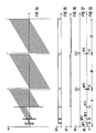
- the phase profile of the spins which results from the RF pulses RF1 to RF5 according to FIG. 1 and from the action of the gradient pulses GR1 to GR5, is shown in FIG. 6.
- the times t1 to t5 are also entered in FIG.
- the phase of the spins excited with the RF pulse RF1 at time t1 initially increases continuously under the effect of the gradient GR1.
- an RF pulse RF2 acts again on the already excited spins.
- the primary spin magnetization generated with the RF pulse RF1 according to the partition model by Woessner (described in J. Chem. Phys. 34, 2057, 1961) is split into three components with respect to the phase: in part the phase is inverted, in part remains it remains unchanged and in part the magnetization is brought into a z position which cannot be influenced by gradients.
- These three components of the spin magnetization are again subjected to excitation with the third RF pulse RF3 at time t3.
- a further RF pulse RF4 splits all components into three further components. Eighteen components with different phase positions are thus available at time t5.
- the FID signals generated by the RF pulses RF2 to RF4 were not considered for the sake of clarity. These signals can also be used for image generation.
- the 180 ° HF pulse RF5 all spin magnetizations inverted. Due to the selective connection of the 180 ° RF pulse RF5, this only applies to the selected layer.
- the phases of the individual components of the spin magnetization increase again linearly under the effect of the gradient GR5 which is switched on at the same time.
- the individual components of the spin magnetization have a phase zero crossing at different times.
- the phase zero crossing is synonymous with focusing, in which a nuclear magnetic resonance signal is generated.
- the nuclear magnetic resonance signals generated during the readout phase B are shown in FIG. 5.
- Eighteen signals were thus generated with four RF excitation pulses RF1 to RF4 and a 180 ° RF pulse RF5. Generally speaking, this is done by splitting up the respectively existing spin magnetization by means of the excitation pulses following the first excitation pulse and focussing the individual sub-groups thus created in a staggered manner.
- the resulting signals contain phase information relating to the direction of the read-out gradient GR5 due to the read-out gradient GR5 that is switched on during the readout phase. Due to the layer selectivity of the 180 ° RF pulse RF5, a local preselection for a specific layer has already been carried out.
- the read-out gradient GR5 is expediently perpendicular to the slice selection gradient GS, so that the read-out gradient GR5 is used for coding with respect to a direction within the selected slice with respect to the phase position.
- phase coding must also be carried out in a third spatial direction.
- a single pulse of a phase coding gradient GP can be switched on between the signals, so that phase coding with respect to the direction of the phase coding gradient, which is expediently perpendicular to the directions of the read-out gradient GR5 and the slice selection gradient GS.
- a pre-phase pulse GPV is provided in the excitation phase A so that the zero crossing of the phase coding lies in the middle line of the raw data matrix to be explained below.
- this pre-phasing pulse GPV is inverted by the 180 ° RF pulse RF5, so that a negative pre-phasing occurs, the effect of which is gradually canceled again during the readout phase B by the individual pulses of the phase coding gradient GP.
- the area of the pre-phasing pulse GPV is dimensioned such that it is equal to the sum of the individual pulses GP up to the middle of the readout phase B.
- the nuclear magnetic resonance signals S shown in FIG. 5 are sampled, digitized in the time domain and the numerical values obtained in this way are entered in a raw data matrix according to FIG.
- the raw data matrix can be viewed as a measurement data space, in the two-dimensional case present in the exemplary embodiment as a measurement data level.
- This measurement data space is generally referred to as "k-space" in magnetic resonance imaging.
- the information necessary for the image generation about the spatial origin of the signal contributions S is coded in the phase factors, the relationship between the location space (ie the image) and the k-space being mathematically related via a two-dimensional Fourier transformation.
- the relationship between the location space (ie the image) and the k-space being mathematically related via a two-dimensional Fourier transformation.
- each line corresponds to an individual signal S.
- An image matrix is obtained from the raw data matrix shown in FIG. 8 by means of two-dimensional Fourier transformation, on the basis of which an image reconstruction then takes place.
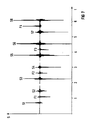
- FIG. 7 shows the signals generated during the readout phase, which are only shown schematically in FIG. 5, on the basis of an actually created plot.
- the evaluated signals are designated S1 to S8, the signals resulting from the FID signals of the RF pulses RF2 to RF4 are designated F1 to F4 and are not evaluated in the exemplary embodiment shown, although this would be possible in principle.
- the individual signals have an irregular amplitude distribution. Without further measures, this would lead to artifacts in the image reconstruction. In fact, scaling due to different attenuations or amplifications in signal processing is therefore necessary in order to achieve a uniform amplitude distribution. Such measures are associated with losses in the signal-to-noise ratio.
- the nuclear magnetic resonance signals generated are also possible by selecting the RF pulse strengths of the RF pulses RF1 to RF4 and their phases.
- the amplitude distribution can be improved by empirical procedures. For example, a flip-angle distribution of 90 ° -75 ° -75 ° -90 ° has proven to be favorable for four RF pulses, so that the smallest variation of the echo amplitudes of 6.96: 1 is obtained.
- phase coding gradients have a significantly smaller amplitude than read-out gradients, so that the requirements for the gradient electronics remain low.
- the recording time is approximately in the range of the EPI procedure.
- pure spin echoes arise which are insensitive to local field inhomogeneities.
- the phase coding can also take place during the excitation phase.
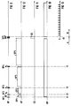
- a corresponding pulse sequence is shown in FIGS. 9 to 13.
- the excitation phase A there is a single pulse GP1 to GP4 of a phase coding gradient GP in the gaps between two RF pulses RF1 to RF5 switched on (FIG 12).
- a phase coding gradient GP is no longer switched on. Since the nuclear spins have a "phase memory", they retain the location-dependent phase information impressed during the excitation phase A even during the readout phase, so that this phase information can be evaluated for spatial resolution.
- This arrangement has the advantage that the switching times of the individual pulses of the phase coding gradient GP become longer than in the exemplary embodiment according to FIGS. 1 to 5.
- the gradient GR remains switched on during the entire excitation phase with the exception of the switch-on time of the RF pulse RF5 in the pulse sequence according to FIG.
- the RF pulses RF1 to RF4 must be very broadband.
- FIG. 6 the phases of the nuclear spins also pass through zero during the excitation phase A, that is to say that they are rephased.
- Nuclear resonance signals also arise here, but are not shown in FIG. 5, since they are not evaluated in the exemplary embodiment described there.
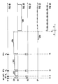
- Such an embodiment is shown in the pulse diagrams according to FIGS 14 to 18.
- the high-frequency pulses RF1 to RF5, the readout gradient GR and the slice selection gradient GS according to FIGS. 14 to 16 are switched as in the exemplary embodiment according to FIGS. 1 to 3.
- FIG. 18 also shows nuclear magnetic resonance signals S during the excitation phase A.
- phase coding gradient GP are also provided during the excitation phase A.
- the pre-phasing pulse GPV must be switched before the first of these single pulses.
- the nuclear spins are imprinted with the phase coding gradients GP1 to GP4, a location-dependent phase, which is stored at the beginning of the readout phase. This means that all signals have location-dependent phase information that is used for image calculation. With this pulse sequence, additional signals can be obtained with the measuring time remaining the same as in the exemplary embodiment according to FIGS.
- a rephasing of the nuclear spins can be achieved not only by a 180 ° HF pulse, but alternatively in a known manner also by a gradient reversal.
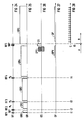
- An exemplary embodiment for a pulse sequence with gradient reversal is shown in FIGS. 19 to 23.
- the 180 ° pulse RF5 is omitted in the sequence of RF pulses RF ..
- the direction of the readout gradient GR5 is inverted with respect to the gradients GR1 to GR4.
- the nuclear magnetic resonance signals S according to FIG. 23 thus no longer arise as spin echoes, but rather as gradient echoes.
- the evaluation can be carried out as in the exemplary embodiment according to FIGS. 1 to 5.
- the slice selection gradient GS is also switched on for each RF pulse RF1 to RF4.
- Each RF pulse RF1 to RF4 is frequency-selective, so that it acts only on a predetermined layer of the examination object under the influence of the assigned slice selection gradient.
- the pre-phasing pulse GPV must also be compared to the individual pulses of the phase coding gradient GP are inverted since, in contrast to the exemplary embodiment according to FIGS. 1 to 5, its effect is not inverted by a 180 ° HF pulse.
- phase coding must also take place in a second direction.
- FIGS. 24 to 28 A first exemplary embodiment of a pulse sequence for generating three-dimensional image information is shown in FIGS. 24 to 28.
- this pulse sequence corresponds to the exemplary embodiment according to FIGS. 1 and 2.
- a pre-phasing gradient in the phase coding direction GPV is also provided.
- the phase coding gradient GP remains switched on during the readout phase. This is not necessarily related to the three-dimensional imaging, but is only intended to show an alternative to the step-wise progression of the phase according to FIGS. 4, 17 and 22.
- the sequence shown In order to obtain three-dimensional image information, the sequence shown must be repeated n times with different values of a phase coding gradient in a second direction. This is indicated in FIG. 26 by several stages of the second phase coding gradient GPS.
- the 180 ° HF pulse RF5 likewise interacts with a slice selection gradient GS. In this case, however, it must not only act on a thin layer, but on a thick layer or disc within which the three-dimensional resolution is to take place. This can be achieved by appropriate selection of the frequency bandwidth of the 180 ° RF pulse RF5.
- FIGS. 29 to 32 Such an exemplary embodiment is shown in FIGS. 29 to 32, the excitation phase being omitted here for the sake of clarity. This can, for example, coincide with the excitation phase A according to FIGS. 1 to 4, but here, too, the 180 ° RF pulse RF5 must act on a thick layer within which a three-dimensional resolution takes place.
- a phase coding pulse GP ' is switched on in a second direction. This will gradually change the phase of the nuclear spins in the second direction.
- the direction of the second phase coding gradient GP ' is perpendicular to the direction of the first phase coding gradient GP and the readout gradient GR.
- n * m location-coded signals are obtained in each case. This is carried out p times with the phase switched due to the second phase coding gradient GP ', so that finally a three-dimensional n * m * p raw data matrix is available, from which an image with three-dimensional location information can be obtained by three-dimensional Fourier transformation.
- FIG. 33 shows the high-frequency pulses RF
- FIG. 34 shows the phase response of the nuclear spins in analogy to FIG. 6
- FIG. 35 shows the course of the Auslegradgrad GR
- FIG 36 shows the course of the phase coding gradient GP
- FIG 37 shows the course of the slice selection gradient GS.
- the resulting nuclear magnetic resonance signals are not shown for reasons of clarity.
- the pulse sequence corresponds to that according to FIGS. 1 to 5 with the exception of the phase coding gradient GP, which is not switched in blips in FIG. 36 but continuously.
- a second 180 ° pulse RF6 is switched on together with a slice selection gradient GS2.
- the phase positions of the nuclear spins are thus inverted as shown in FIG. 34.
- the second 180 ° high-frequency pulse RF6 acts like the first 180 ° high-frequency pulse RF5 layer-selectively.
- a second readout phase B2 now follows, in which, under the effect of a readout gradient GR, the phase of the spins starts up again as shown in FIG.
- a nuclear magnetic resonance signal is generated at each zero crossing of the phase, but this is not shown in the figures for the sake of clarity.
- a phase coding gradient GP is also switched on, the direction of which is inverted with respect to the first readout phase B1.
- the same k-space can also be scanned again in the readout phase B2, for example in order to obtain images of the same slice that are close in time or to scan different slices selected by dimensioning the slice selection gradient GS.
- the signals generated during the readout phase were only shown schematically. 7 shows an example using an experimentally created plot for the actual waveform.
- the evaluated signals are designated S1 to S8, the signals resulting from the FID signals of the RF pulses RF2 to RF4 are designated F1 to F4 and are not evaluated in the exemplary embodiment shown, although this would be possible in principle.
- the individual signals have an irregular amplitude distribution. Without further measures, this would lead to artifacts in the image reconstruction. In fact, scaling due to different attenuations or amplifications in signal processing is therefore necessary in order to achieve a uniform amplitude distribution.
- the reference signals obtained in this way can be entered in a reference matrix.
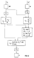
- This procedure is shown schematically in a flow diagram according to FIG. 43.
- the non-phase-coded nuclear magnetic resonance signals are denoted by S ij , the phase-coded nuclear magnetic resonance signals by S ij P.
- i indicates the row number, j the column number.
- the signals S ij are entered in a measurement matrix MR, the signals S ij P are entered in a measurement matrix M.
- Both matrices are Fourier transformed in the row direction (corresponding to the direction of the readout gradient), which is designated FT L in FIG. 43.
- Pixel a phase information of the measurement signals S ij-containing size P ij as the quotient of the phase-coded signals S ij P and the non-phase-coded signals S ij is formed.
- averaging over all rows i is carried out in the measurement matrix transformed in the Fourier direction, so that N signals are obtained with a measurement matrix with M rows and N columns S j receives. These signals correspond to an average over all projections.
- 2 for i 1 ... M.
- 2 ⁇ 16Q b ij 0 if the above condition is not met.
- an amplitude limitation is carried out, for example with the division S ij P / S ij being prevented from leading to random, meaningless values outside the object, for example due to noise.
- a Fourier transformation is then carried out in the column direction (denoted FT c ) in the matrix with the quantities b ij , so that the image matrix B is finally obtained, on the basis of which an image of the examined object can be built up.
- the signals S ij for creating the reference matrix MR can For example, can be obtained in a complete excitation readout cycle, but this leads to a corresponding extension of the measurement time. However, it is also possible to use the signals S obtained during the excitation phase A, as are shown, for example, in FIG. 18, to create the reference matrix MR, only any phase coding for these signals being omitted.
- the exemplary embodiments shown represent only individual possibilities of the large number of pulse sequences for realizing the invention. E.g. a combination of the pulse sequences shown is possible. For example, everywhere the phase coding gradient remains switched on as in FIG. 27 instead of being implemented in individual pulses. Furthermore, in all exemplary embodiments, the signals S can also be implemented by inversion of the readout gradient according to FIG. 20. As in FIG. 21, the slice selection can also relate to all HF pulses.
Landscapes
- Physics & Mathematics (AREA)
- Health & Medical Sciences (AREA)
- General Health & Medical Sciences (AREA)
- Nuclear Medicine, Radiotherapy & Molecular Imaging (AREA)
- Radiology & Medical Imaging (AREA)
- Engineering & Computer Science (AREA)
- Signal Processing (AREA)
- High Energy & Nuclear Physics (AREA)
- Condensed Matter Physics & Semiconductors (AREA)
- General Physics & Mathematics (AREA)
- Magnetic Resonance Imaging Apparatus (AREA)
Claims (28)
- Procédé pour exploiter un appareil à résonance magnétique nucléaire avec une séquence d'impulsions, comprenant une phase d'excitation (A) et une phase suivante de lecture (B), avec les étapes suivantes :a) pendant la phase d'excitation (A), on applique une suite d'impulsions d'excitation (F1 à F4), un premier gradient (GR1 à GR4) étant appliqué dans une première direction au moins pendant les pauses entre les impulsions d'excitation et les surfaces de ce gradient étant respectivement différentes entre deux impulsions respectives d'excitation (FR1 à FR4);b) on applique une impulsion HF à 180° (RF5);c) pendant la phase de lecture (B), on lit les signaux de résonance nucléaire apparus (S), sous un gradient de lecture (GR5), qui possède au moins une composante dans la première direction;d) on analyse les signaux de résonance nucléaire (S), du point de vue valeur absolue et phase, et à partir de là, on reconstitue une image.
- Procédé pour exploiter un appareil à résonance magnétique nucléaire avec une séquence d'impulsions, comprenant une phase d'excitation (A) et une phase suivante de lecture (B), avec les étapes suivantes :a) pendant la phase d'excitation (A), on applique une suite d'impulsions d'excitation (F1 à F4), un premier gradient (GR1 à GR4) étant appliqué dans une première direction au moins pendant les pauses entre les impulsions d'excitation et les surfaces de ce gradient étant respectivement différentes entre deux impulsions respectives d'excitation (FR1 à FR4);b) -c) pendant la phase de lecture (B), on lit les signaux de résonance nucléaire apparus (S), sous un gradient de lecture (GR5), qui possède au moins une composante en sens opposé de la première direction;d) on analyse les signaux de résonance nucléaire (S), du point de vue valeur absolue et phase, et à partir de là, on reconstitue une image.
- Procédé suivant la revendication 1 ou 2, caractérisé par le fait que les surfaces du gradient entre les impulsions d'excitation sont réparties de telle sorte que les signaux d'échos de résonance nucléaire, utilisés pour la formation de l'image, ne se superposent pas pendant la phase de lecture (B).
- Procédé suivant la revendication 3, caractérisé par le fait que les surfaces de gradient augmentent au moins du facteur 3, en étant triées en fonction de la taille, d'une impulsion d'excitation (FR1 à FR4) à la suivante.
- Procédé suivant l'une des revendications 1 à 4, caractérisé par le fait que la somme de l'angle de basculement (flip) des impulsions d'excitation (F1 à F4), introduites pendant la phase d'excitation (A), est nettement supérieure à 180°.
- Procédé suivant la revendication 5, caractérisé par le fait que l'angle de basculement de la première impulsion d'excitation (RF1) est égal à 90° et que l'angle de basculement des autres impulsions d'excitation est compris entre 60° et 90°.
- Procédé suivant l'une des revendications 1 à 6, caractérisé par le fait que pendant l'étape c), on applique un gradient de codage de phase (GP) perpendiculairement à la première direction.
- Procédé suivant la revendication 7, caractérisé par le fait qu'on applique le gradient de codage de phase (GP) uniquement entre les différents signaux de résonance nucléaire (S).
- Procédé suivant la revendication 7, caractérisé par le fait que le gradient de codage de phase (GP) reste appliqué pendant la phase de lecture (B).
- Procédé suivant l'une des revendications 1 à 9, caractérisé par le fait que pendant la phase d'excitation (A), on applique un gradient de codage de phase (GP1-GP4) perpendiculairement à la première direction.
- Procédé suivant l'une des revendications 1 à 10, caractérisé par le fait que également pendant la phase d'excitation (11), des signaux (S′) sont lus et sont utilisés pour la reconstitution de l'image.
- Procédé suivant l'une des revendications 1 ou 3 à 11, caractérisé par le fait que l'impulsion HF à 180° (RF5) est sélective du point de vue de la fréquence et est émise sous l'action d'un second gradient (GS) perpendiculaire au premier gradient et éventuellement au gradient de codage de phase, de sorte que seuls les spins sont inversés dans une couche sélectionnée.
- Procédé suivant l'une des revendications 1 à 12, caractérisé par le fait que toutes les impulsions d'excitation (RF1 à RF4) sont sélectives du point de vue des couches.
- Procédé suivant l'une des revendications 1 à 13, caractérisé par le fait que les surfaces du premier gradient sont en progression géométrique entre deux impulsions successives d'excitation (RF1 à RF4), à partir de la seconde impulsion d'excitation (RF2).
- Procédé suivant l'une des revendications 1 à 13, caractérisé par le fait que grâce au choix de l'angle de basculement des impulsions d'excitation HF (RF1 à RF4), on exécute une optimisation de la distribution d'amplitude des signaux de résonance nucléaire (RS) dans l'espace k pendant la phase de lecture (B).
- Procédé suivant l'une des revendications 1 à 15, caractérisé par le fait que le codage de phase est commandé de telle sorte que la distribution d'amplitude est optimisée dans l'espace k.
- Procédé suivant l'une des revendications 1 à 16, caractérisé par le fait que grâce à l'application d'un second gradient de codage de phase (GP′) perpendiculairement au premier gradient de codage de phase (GP) et au gradient de lecture (GR), on exécute, en supplément, un codage de phase dans la direction du second gradient de codage de phase (GP′), que le second gradient de codage de phase (GP′) prend n valeurs différentes pendant n phases successives d'excitation et de lecture, et que lors de la reconstitution d'une image, une résolution locale tridimensionnelle est exécutée.
- Procédé suivant l'une des revendications 1 à 16, caractérisé par le fait que sous l'effet de l'application d'un second gradient de codage de phase (GP′) perpendiculairement au premier gradient de codage de phase (GP) et au gradient de lecture (GR), on applique, en supplément, un codage de phase dans la direction du second gradient de codage de phase, que le second gradient de codage de phase (GP′) est appliqué pendant une seule phase d'excitation et de lecture avec n valeurs différentes, de sorte que la phase du signal de résonance nucléaire est codée dans la direction du second gradient de codage de phase (GP), et que lors de la reconstitution de l'image, on obtient une résolution locale tridimensionnelle.
- Procédé suivant l'une des revendications 1 à 18, caractérisé par le fait que des signaux de mesure possédant une distribution d'amplitude optimisée sont produits dans l'espace k, au moyen d'un cadrage d'échelle différent, à partir des différents signaux de résonance nucléaire (S).
- Procédé suivant l'une des revendications 1 à 19, caractérisé par le fait qu'on obtient deux ensembles de signaux de résonance nucléaire, dont seul un ensemble est codé selon un codage de phase et que l'ensemble, non codé selon un codage de phase, de signaux de résonance nucléaire est utilisé en tant que valeur de référence pour le cadrage d'échelle de l'amplitude des signaux.
- Procédé suivant la revendication 20, caractérisé par le fait qu'on forme deux séquences complètes d'impulsions possédant une phase d'excitation et une phase de lecture, les signaux de résonance nucléaire étant une fois codés, une fois non codés selon un codage de phase.
- Procédé suivant la revendication 20, caractérisé par le fait que l'ensemble de signaux de résonance nucléaire, non codés selon un codage de phase, est obtenu pendant la phase d'excitation.
- Procédé suivant l'une des revendications 1 à 20, caractérisé par le fait que dans le cas de l'utilisation de symétries dans la variation d'amplitude des signaux de résonance nucléaire, on obtient juste le nombre de signaux de résonance nucléaire non codés selon un codage de phase, qui est nécessaire pour une détection de la distribution d'amplitude.
- Procédé suivant l'une des revendications 1 à 23, caractérisé par le fait que l'ensemble, codé selon un codage de phase, de signaux de résonance nucléaire est introduit dans une matrice de données brutes (M), et l'ensemble, non codé selon un codage de phase, de signaux de résonance nucléaire est introduit dans une matrice de référence (MR), qu'une transformation de Fourier est exécutée dans le sens de la lecture dans les deux matrices (M, MR), que chaque signal individuel dans la matrice obtenue à partir de la matrice de données brutes (M) est divisé par le signal correspondant présent dans la matrice obtenue à partir de la matrice de référence (MR) et qu'une matrice d'image (B) est établie au moyen d'une transformation de Fourier dans le sens du codage de phase.
- Procédé suivant l'une des revendications 1 ou 3 à 24, caractérisé par le fait qu'après l'étape c), au moins une autre impulsion Hf à 180° est appliquée et qu'après chaque autre impulsion Hf à 180°, des signaux de résonance nucléaire sont détectés pendant respectivement une autre phase de lecture (B2), sous un gradient de lecture (GR), qui possède au moins une composante dans la première direction.
- Procédé suivant la revendication 25, caractérisé par le fait que pendant les autres phases de lecture (B1,B2) on applique un gradient de codage de phase (GP), dont le signe change d'une phase de lecture à la suivante.
- Procédé suivant l'une des revendications 1 à 24, caractérisé par le fait qu'après l'étape c), le gradient de lecture est inversé au moins une fois et que pendant au moins une autre phase de lecture, des signaux de résonance nucléaire sont détectés sous l'action du gradient de lecture.
- Procédé suivant la revendication 27, caractérisé par le fait qu'un gradient de codage de phase est appliqué pendant chaque phase de lecture (B1,B2).
Applications Claiming Priority (4)
| Application Number | Priority Date | Filing Date | Title |
|---|---|---|---|
| DE4207930 | 1992-03-12 | ||
| DE4207930 | 1992-03-12 | ||
| DE4226446 | 1992-08-10 | ||
| DE4226446 | 1992-08-10 |
Publications (2)
| Publication Number | Publication Date |
|---|---|
| EP0560168A1 EP0560168A1 (fr) | 1993-09-15 |
| EP0560168B1 true EP0560168B1 (fr) | 1995-07-26 |
Family
ID=25912737
Family Applications (1)
| Application Number | Title | Priority Date | Filing Date |
|---|---|---|---|
| EP93103238A Expired - Lifetime EP0560168B1 (fr) | 1992-03-12 | 1993-03-01 | Séquence d'impulsions pour un appareil à résonance magnétique nucléaire |
Country Status (4)
| Country | Link |
|---|---|
| US (1) | US5432448A (fr) |
| EP (1) | EP0560168B1 (fr) |
| JP (1) | JPH0622929A (fr) |
| DE (1) | DE59300388D1 (fr) |
Families Citing this family (15)
| Publication number | Priority date | Publication date | Assignee | Title |
|---|---|---|---|---|
| GB9217718D0 (en) * | 1992-08-20 | 1992-09-30 | British Tech Group | Method of and apparatus for nmr testing |
| US6034528A (en) * | 1994-03-31 | 2000-03-07 | Siemens Aktiengesellschaft | Method for operating a nuclear magnetic resonance tomography apparatus |
| DE4423806C2 (de) * | 1994-07-06 | 2000-08-24 | Siemens Ag | Verfahren zur MR-Bildgewinnung mit einer Folge von Einzelmessungen |
| DE4430460C2 (de) * | 1994-08-27 | 1999-06-17 | Hennig Juergen Prof Dr | Verfahren der bildgebenden Kernspintomographie zur simultanen Erzeugung mehrerer Schichtbilder |
| DE19511794B4 (de) * | 1995-03-30 | 2005-12-29 | Siemens Ag | Verfahren zur Gewinnung von Bilddaten in einem Kernspintomographiegerät und Kernspintomographiegerät zur Durchführung des Verfahrens |
| USRE48347E1 (en) | 2000-12-21 | 2020-12-08 | University Of Virginia Patent Foundation | Method and apparatus for spin-echo-train MR imaging using prescribed signal evolutions |
| USRE45725E1 (en) | 2000-12-21 | 2015-10-06 | University Of Virginia Patent Foundation | Method and apparatus for spin-echo-train MR imaging using prescribed signal evolutions |
| US6650115B2 (en) * | 2001-10-12 | 2003-11-18 | The Board Of Trustees Of The Leland Stanford Junior University | Variable density fourier velocity encoding MR imaging |
| DE102007021719B4 (de) * | 2007-05-09 | 2010-09-30 | Siemens Ag | Turbospinechobildgebungssequenz mit langen Echozügen und optimiertem T1-Kontrast |
| WO2010056749A1 (fr) * | 2008-11-12 | 2010-05-20 | Jang-Yeon Park | Séquence d'échantillonnage radiale en 3d à temps d'écho (te) court pour imagerie à résonance magnétique |
| DE102012208425B4 (de) | 2012-05-21 | 2013-12-12 | Siemens Aktiengesellschaft | Kontinuierliches Korrigieren von Phasenfehlern einer multidimensionalen, ortsselektiven Magnetresonanz-Messsequenz |
| DE102013100349B4 (de) * | 2013-01-14 | 2016-05-12 | Siemens Aktiengesellschaft | Echoplanare MR-Bildgebung mit zickzack-artigen k-Raum-Trajektorien |
| CN104280703B (zh) * | 2014-09-28 | 2017-01-18 | 中国石油大学(华东) | 一种基于脉冲梯度磁场的d‑t2脉冲施加方法 |
| US11307278B2 (en) * | 2020-01-02 | 2022-04-19 | General Electric Company | Reconstruction of MR image data |
| CN116359814A (zh) * | 2023-04-07 | 2023-06-30 | 深圳市联影高端医疗装备创新研究院 | 多核成像序列确定方法、装置和磁共振系统 |
Citations (1)
| Publication number | Priority date | Publication date | Assignee | Title |
|---|---|---|---|---|
| DE3823398A1 (de) * | 1988-07-09 | 1990-01-11 | Spectrospin Ag | Verfahren zur erzeugung einer folge von spinechosignalen, die verwendung dieses verfahrens bei der kernspintomographie und vorrichtung zum durchfuehren bzw. zur verwendung dieses verfahrens |
Family Cites Families (6)
| Publication number | Priority date | Publication date | Assignee | Title |
|---|---|---|---|---|
| GB2107469B (en) * | 1981-09-21 | 1985-09-18 | Peter Mansfield | Nuclear magnetic resonance methods |
| DE3434161A1 (de) * | 1984-09-18 | 1986-03-27 | Bruker Medizintechnik Gmbh, 7512 Rheinstetten | Verfahren zum messen der magnetischen kernresonanz |
| IL79076A (en) * | 1986-06-10 | 1989-10-31 | Elscint Ltd | Restricted volume imaging |
| US4847560A (en) * | 1986-08-15 | 1989-07-11 | Picker International, Inc. | Simultaneous multislice-multiangle images without saturation bands |
| DE3726932A1 (de) * | 1987-08-13 | 1989-02-23 | Spectrospin Ag | Verfahren zum kodieren von n parametern bei der mehrdimensionalen fourier-nmr-spektroskopie |
| DE4035410C2 (de) * | 1989-11-20 | 2000-03-16 | Siemens Ag | Pulssequenz nach dem Echoplanarverfahren |
-
1993
- 1993-03-01 EP EP93103238A patent/EP0560168B1/fr not_active Expired - Lifetime
- 1993-03-01 DE DE59300388T patent/DE59300388D1/de not_active Expired - Fee Related
- 1993-03-12 JP JP5051842A patent/JPH0622929A/ja active Pending
-
1994
- 1994-09-20 US US08/308,970 patent/US5432448A/en not_active Expired - Lifetime
Patent Citations (1)
| Publication number | Priority date | Publication date | Assignee | Title |
|---|---|---|---|---|
| DE3823398A1 (de) * | 1988-07-09 | 1990-01-11 | Spectrospin Ag | Verfahren zur erzeugung einer folge von spinechosignalen, die verwendung dieses verfahrens bei der kernspintomographie und vorrichtung zum durchfuehren bzw. zur verwendung dieses verfahrens |
Also Published As
| Publication number | Publication date |
|---|---|
| EP0560168A1 (fr) | 1993-09-15 |
| JPH0622929A (ja) | 1994-02-01 |
| DE59300388D1 (de) | 1995-08-31 |
| US5432448A (en) | 1995-07-11 |
Similar Documents
| Publication | Publication Date | Title |
|---|---|---|
| EP0074022B1 (fr) | Dispositif de tomographie à spin nucléaire | |
| DE3434161C2 (fr) | ||
| EP0184840B1 (fr) | Arrangement pour l'examen par résolution spatiale d'un échantillon à l'aide de la résonnance magnétique des moments de spin | |
| DE10246406B4 (de) | MRI mit sich bewegendem Tisch und einer Frequenzkodierung in der z-Richtung | |
| DE3331396C2 (fr) | ||
| DE69735291T2 (de) | Verfahren und vorrichtung zur bilderzeugung durch magnetresonanz | |
| EP0560168B1 (fr) | Séquence d'impulsions pour un appareil à résonance magnétique nucléaire | |
| DE102013100349B4 (de) | Echoplanare MR-Bildgebung mit zickzack-artigen k-Raum-Trajektorien | |
| DE19524184B4 (de) | Pulssequenz zur schnellen Bildgebung in der Kernspintomographie | |
| DE4024164A1 (de) | Verfahren zur verbesserung des signal-rausch-verhaeltnisses bei einem kernspin-tomographiegeraet | |
| EP0753158B1 (fr) | Sequence d'impulsions pour un appareil de remnographie | |
| EP0378628B1 (fr) | Procede et dispositif de generation d'une sequence de signaux d'echo du spin, et utilisation de ces procede et dispositif en tomographie a spin nucleaire | |
| DE68927874T2 (de) | Vorrichtung zur Bilderzeugung mittels magnetischer Resonanz | |
| DE4139509C2 (de) | Bildgebendes Verfahren für ein Kernspintomographiegerät, das eine Pulssequenz nach dem Echoplanarverfahren verwendet | |
| DE4415393B4 (de) | Verfahren zur Erzeugung von Bildern in einem Kernspintomographiegerät mit einer Spinecho-Pulssequenz | |
| DE4024161A1 (de) | Pulssequenz zur schnellen ermittlung von bildern der fett- und wasserverteilung in einem untersuchungsobjekt mittels der kernmagnetischen resonanz | |
| EP0357100A2 (fr) | Procédé tomographique à résonance nucléaire et tomographe à résonance nucléaire pour la mise en oeuvre de ce procédé | |
| EP0576712A1 (fr) | Séquence d'impulsions d'imagérie rapide pour la tomographie à spin nucléaire | |
| EP0199202A1 (fr) | Dispositif de résonance de spin nucléaire | |
| DE2936465A1 (de) | Verfahren zur erstellung von kernresonanzbildern | |
| DE3718344A1 (de) | Abbildungsverfahren fuer magnetische kernresonanz | |
| EP1107015B1 (fr) | Procédé de la résonance magnétique pour la génération d'impulsions navigatrices | |
| DE4219610C1 (de) | NMR-Bildgebungsverfahren mit Einzelpunktaufnahme (SPI) | |
| DE4423806C1 (de) | Verfahren zur MR-Bildgewinnung mit einer Folge von Einzelmessungen | |
| EP0413266B1 (fr) | Méthode pour mesurer simultanément des signaux RMN, en particulier pour déterminer les flux sanguins en tomographie RMN, avec l'aide de la méthode Multiple Slice Fourier Flow (= MUFF) |
Legal Events
| Date | Code | Title | Description |
|---|---|---|---|
| PUAI | Public reference made under article 153(3) epc to a published international application that has entered the european phase |
Free format text: ORIGINAL CODE: 0009012 |
|
| AK | Designated contracting states |
Kind code of ref document: A1 Designated state(s): DE ES FR GB IT |
|
| 17P | Request for examination filed |
Effective date: 19931020 |
|
| 17Q | First examination report despatched |
Effective date: 19940202 |
|
| GRAA | (expected) grant |
Free format text: ORIGINAL CODE: 0009210 |
|
| AK | Designated contracting states |
Kind code of ref document: B1 Designated state(s): DE ES FR GB IT |
|
| PG25 | Lapsed in a contracting state [announced via postgrant information from national office to epo] |
Ref country code: IT Free format text: LAPSE BECAUSE OF FAILURE TO SUBMIT A TRANSLATION OF THE DESCRIPTION OR TO PAY THE FEE WITHIN THE PRESCRIBED TIME-LIMIT;WARNING: LAPSES OF ITALIAN PATENTS WITH EFFECTIVE DATE BEFORE 2007 MAY HAVE OCCURRED AT ANY TIME BEFORE 2007. THE CORRECT EFFECTIVE DATE MAY BE DIFFERENT FROM THE ONE RECORDED. Effective date: 19950726 Ref country code: ES Free format text: THE PATENT HAS BEEN ANNULLED BY A DECISION OF A NATIONAL AUTHORITY Effective date: 19950726 |
|
| REF | Corresponds to: |
Ref document number: 59300388 Country of ref document: DE Date of ref document: 19950831 |
|
| GBT | Gb: translation of ep patent filed (gb section 77(6)(a)/1977) |
Effective date: 19950908 |
|
| ET | Fr: translation filed | ||
| PLBE | No opposition filed within time limit |
Free format text: ORIGINAL CODE: 0009261 |
|
| STAA | Information on the status of an ep patent application or granted ep patent |
Free format text: STATUS: NO OPPOSITION FILED WITHIN TIME LIMIT |
|
| 26N | No opposition filed | ||
| PGFP | Annual fee paid to national office [announced via postgrant information from national office to epo] |
Ref country code: GB Payment date: 19970224 Year of fee payment: 5 |
|
| PGFP | Annual fee paid to national office [announced via postgrant information from national office to epo] |
Ref country code: FR Payment date: 19970321 Year of fee payment: 5 |
|
| PG25 | Lapsed in a contracting state [announced via postgrant information from national office to epo] |
Ref country code: GB Free format text: LAPSE BECAUSE OF NON-PAYMENT OF DUE FEES Effective date: 19980301 |
|
| PG25 | Lapsed in a contracting state [announced via postgrant information from national office to epo] |
Ref country code: FR Free format text: THE PATENT HAS BEEN ANNULLED BY A DECISION OF A NATIONAL AUTHORITY Effective date: 19980331 |
|
| GBPC | Gb: european patent ceased through non-payment of renewal fee |
Effective date: 19980301 |
|
| REG | Reference to a national code |
Ref country code: FR Ref legal event code: ST |
|
| PGFP | Annual fee paid to national office [announced via postgrant information from national office to epo] |
Ref country code: DE Payment date: 20040517 Year of fee payment: 12 |
|
| PG25 | Lapsed in a contracting state [announced via postgrant information from national office to epo] |
Ref country code: DE Free format text: LAPSE BECAUSE OF NON-PAYMENT OF DUE FEES Effective date: 20051001 |