EP0560195A2 - Indicateur du temps de travail réel - Google Patents
Indicateur du temps de travail réel Download PDFInfo
- Publication number
- EP0560195A2 EP0560195A2 EP93103385A EP93103385A EP0560195A2 EP 0560195 A2 EP0560195 A2 EP 0560195A2 EP 93103385 A EP93103385 A EP 93103385A EP 93103385 A EP93103385 A EP 93103385A EP 0560195 A2 EP0560195 A2 EP 0560195A2
- Authority
- EP
- European Patent Office
- Prior art keywords
- voltage
- power
- operating time
- actual operating
- input power
- Prior art date
- Legal status (The legal status is an assumption and is not a legal conclusion. Google has not performed a legal analysis and makes no representation as to the accuracy of the status listed.)
- Granted
Links
Images


Classifications
-
- G—PHYSICS
- G01—MEASURING; TESTING
- G01R—MEASURING ELECTRIC VARIABLES; MEASURING MAGNETIC VARIABLES
- G01R21/00—Arrangements for measuring electric power or power factor
- G01R21/133—Arrangements for measuring electric power or power factor by using digital technique
Definitions
- the present invention relates to an actual operating time indicator, more particularly, it relates to an actual operating time indicator for indicating an actual operating time of a hoist apparatus on a digital display.
- the present invention is advantageously used for an electric hoist apparatus which lifts a load up/down by using a motor, for example, a three-phase induction motor.
- a hoist apparatus for lifting a load up/down is widely used in various fields, for example, in a factory, a warehouse, construction and the like.
- the present invention relates to the electric hoist apparatus.
- an electric hoist apparatus has two motors, i.e., one is a lifting motor for lifting a load up/down, and the other is a travelling motor for moving the hoist apparatus in a traverse direction on a beam.
- the lifting motor is usually formed by a three-phase induction motor because of a simple/firm structure, relatively low cost and high power.
- the lifting motor is defined by at least a rating load indicating a weight of a load in normal use, output power at the rating load, rating time for indicating a range of continuous use time, and a test load for indicating a maximum load.
- the hoist apparatus may be temporarily used in an overload state or over-time state. Accordingly, it is necessary to obtain precise data which can be utilized for maintenance of the apparatus after use for a certain time period. For example, it is necessary to precisely measure a relationship between a load and an operating time from a start point of use.
- the actual operating time of the hoist apparatus is displayed by either an integrating wattmeter or a counter.
- the former merely indicates a so-called “total power-on time” for a certain period of time, and the latter merely indicates a number of times the hoist apparatus is operated.
- the influence of a load during actual use of the hoist apparatus is not considered, for example, in an overload state or over-time state, so that it is impossible to precisely measure the actual operating time while taking the load into consideration.
- the life span of a mechanism varies depending on the load during use
- the relationship between the life span of the mechanism and the load when measuring the actual operating time of the hoist apparatus is not considered. Accordingly, in the conventional art, the data are insufficient for maintenance so that it is impossible to efficiently maintain the hoist apparatus.
- the object of the present invention is to provide an actual operating time indicator enabling precise measurement of an actual operating time of a hoist apparatus, particularly, a lifting motor for lifting a load up/down.
- an actual operating time indicator including: a lifting motor for lifting a load up/down; a power detection unit for detecting an input power based on a current and a voltage supplied to the motor, and converting the input power into a first voltage proportional to the input power; a voltage-to-periodic pulse conversion unit connected to the power detection unit for receiving the first voltage and converting the first voltage into a periodic pulse proportional to the first voltage; a counter unit connected to the voltage-to-periodic pulse conversion unit for counting and integrating the periodic pulse to obtain an integrated power; and a display operatively connected to the counter unit for indicating the integrated power as an actual operating time of the motor.
- the actual operating time indicator further includes a divider connected to the counter unit for dividing the integrated power by a power rating which is equivalent to the input power per unit hour when lifting up a rated load.
- the actual operating time indicator further includes a BCD unit operatively connected to the counter unit for converting a binary number into a decimal number to display the actual operating time on the display unit.
- an actual operating time indicator including: a lifting motor for lifting a load up/down; a power detection unit for detecting an input power based on a current and a voltage supplied to the motor, converting the input power into a first voltage proportional to the input power, and further converting the first voltage into a second voltage which is converted based on a predetermined formula defined by relationship between a rating load and a life span of a mechanism; a voltage-to-periodic pulse conversion unit connected to the power detection unit for receiving the second voltage and converting the second voltage into the periodic pulse proportional to the second voltage; a counter unit connected to the voltage-to-periodic pulse conversion unit for counting and integrating the periodic pulse to obtain an integrated power; and a display operatively connected to the counter unit for indicating the integrated power as an actual operating time of the motor.
- the predetermined formula is expressed by Lh ⁇ (1/P) n where, Lh is a life span of a mechanism, P is a weight of a load, and n is an integer determined by a material of the mechanism.
- the power detection unit includes an input voltage conversion unit for obtaining the second voltage
- the input voltage conversion unit is formed by: a first calculation unit inputting the first voltage Vb and a rating voltage VaH which is given by the voltage proportional to the rating input power of the lifting motor during the high speed lifting up operation, and calculates the formula (Vb/VaH)2; a second calculation unit inputting the first voltage Vb and a rating voltage VaL which is given by the voltage proportional to the rated input power of the lifting motor during the low speed lifting up operation, and calculates the formula (Vb/VaL)2; the first voltage being given by half of the rating voltage VaH or VaL so that the formula (Vb/VaH or VaL)2 is given by (1/2)2; a selector for selecting either an output of the first calculation unit or an
- the actual operating time indicator includes: a lifting motor for lifting a load up/down; a power detection unit for detecting an input power based on a current and a voltage supplied to the motor, and converting the input power into a first voltage proportional to the input power; a microcomputer connected to the power detection unit for receiving the first voltage and outputting an integrated power; and a display connected to the microcomputer indicating the integrated power as an actual operating time of the motor.
- the microcomputer includes an analog-to-digital converter, an input port, a central processing unit (CPU), a read only memory (ROM) for storing a basic program for calculation by the CPU, a random access memory (RAM) for temporarily storing a result of the calculation by the CPU, a backup memory, and an output port;
- the A/D converter converts the first voltage Vb into a digital value, and further converts a rating voltage VaH or VaL into a digital value;
- the CPU calculates the following; first, digitized Vb/VaH or Vb/VaL; second, digitized (Vb/VaH)2 or (Vb/VaL)2, and third, digitized Vb ⁇ (Vb/VaH)2 or Vb ⁇ (Vb/VaL)2;
- the CPU counts the result of the calculation and obtains the total number of the count, and divides the total number of the count by a constant (K) which corresponds to an input power rating; and the display indicates
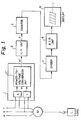
- FIG. 1 is a block diagram of an actual operating time indicator according to a first embodiment of the present invention.
- M denotes a three-phase induction motor used as the lifting motor and operated by AC 200 (v) commercial power.
- Reference number 1 denotes a power detection unit including an ampere meter A, a volt meter V, and a power-to-voltage conversion unit 11.
- Reference number 2 denotes a voltage-to-periodic pulse conversion unit V/F
- 3 denotes a counter for counting periodic pulses
- 4 denotes a divider
- 5 denotes a BCD (binary coded decimal) unit
- 6 denotes a display unit for indicating an actual operating time.
- the lifting motor M has three phases i.e., "T”, "S” and “R” phases.
- the ampere meter A is connected in series to the T phase, and the volt meter V is connected in parallel between the T and S phases to detect the current and voltage applied to the lifting motor M.
- the power-to-voltage conversion unit 11 is provided for obtaining a first voltage "e1" proportional to an input power W to the lifting motor M.
- the input power W of the lifting motor M can be obtained by multiplying the current A by the voltage V and a power-factor since the power is alternating current.
- the change of the current A is converted to the change of a voltage V A (not shown) by flowing the current A through a predetermined constant resistor (not shown), and the voltage V A is multiplied by the voltage V using a known multiplier (not shown) so that it is possible to obtain the voltage "e1" proportional to the input power W to the lifting motor M.
- the voltage-to-frequency conversion unit 2 is provided for converting the voltage "e1" from the power-to-voltage conversion unit 11 into a periodic pulse "f".
- a known digital volt meter utilizes voltage-to-frequency conversion. That is, the digital volt meter counts the periodic pulses to obtain the voltage. This is because that the periodic pulse obtained by the voltage-to-frequency conversion unit is proportional to the measured voltage. Accordingly, the voltage-to-frequency conversion unit 2 outputs a periodic pulse proportional to the input power.
- the counter 3 is provided for counting the periodic pulse "f" from the voltage-to-frequency conversion unit 2. Accordingly, the total count of the counter 3 corresponds to the integrated power.
- the divider 4 is provided for dividing the integrated power by a power rating.
- the power rating is equivalent to the power per unit hour (i.e., a unit power) when lifting up a rated load.
- the integrated power is divided by the unit power, it is possible to obtain the "total power-on time" which is converted to the load rating.
- the “total power-on time” of the above is different from the conventional "power-on time", and it becomes the “total power-on time” taking the use of the hoist apparatus into consideration. Accordingly, it is possible to obtain precise data for maintenance.
- the BCD unit 5 is provided for converting the binary number from the divider 4 into a decimal number to display the actual operating time on the display unit 6.
- FIG. 2 is a block diagram of an actual operating time indicator according to a second embodiment of the present invention.
- the same reference numbers as used in Fig. 1 are attached to the same components in this drawing. Since the components 2 to 6 have already been explained in relation to Fig. 1, the explanation will be omitted for this drawing.
- the power detection unit 1' of this embodiment further includes an input voltage conversion unit 12.
- the input voltage conversion unit 12 is provided for converting the voltage "e1" into a voltage "e2" taking the life span of the mechanism into consideration as explained in detail below. That is, the voltage "e1" from the power-to-voltage conversion unit 11 is converted to the voltage "e2" based on a predetermined formula indicating the relationship between the load and the life span of the mechanism. Then, the voltage "e2" is sent to the voltage-to-periodic pulse conversion unit 2, and the same processes as explained in relation to Fig. 1 are performed in the components 3 to 6.
- the integer “n” is defined in the Japanese Industrial Standard (JIS B 8815 (electric chain-block)) and the European Machine Conveyance Association (FEM). In these documents, the integer “n” is experimentally given by the numeral "3".
- the formula (1) becomes as follows. Lh ⁇ (1/P)3 (2) Accordingly, the input voltage conversion unit 12 of the present invention is formed based on the formula (2) as explained below.
- Figure 3 is a detailed block diagram of an input voltage conversion unit shown in Fig. 2.
- reference number 121 denotes a first calculation unit
- 122 denotes a second calculation unit
- 123 denotes a third calculation unit
- 124 denotes a selector.
- the voltage VaH is given by a voltage proportional to the rated input power of the lifting motor at the high speed
- the voltage VaL is given by the voltage proportional to the rated input power of the lifting motor at the low speed
- the voltage Vb corresponds to the voltage "e1" from the power-to-voltage conversion unit 11.
- the selector 124 is provided for selecting either the high speed or the low speed (HIGH/LOW) of the lifting up/down operation. In general, this selector is switched by an operator from a control box shown in Fig. 6. As shown in the drawing, the selector switches either the output of the first calculation unit 121 or the output of the second calculation unit 122.
- FIG. 4 is another block diagram of an actual operating time indicator shown in Fig. 2.
- the same reference numbers as used in Figs. 1 and 2 are attached to the same components in this drawing.
- "M” denotes a microcomputer.
- the microcomputer M includes an analog-to-digital converter (A/D), an input port (IP), a central processing unit (CPU), a read only memory (ROM), a random access memory (RAM), a backup memory, and an output port (OP).
- A/D analog-to-digital converter
- IP input port
- CPU central processing unit
- ROM read only memory
- RAM random access memory
- OP output port
- the microcomputer has functions of the input voltage conversion unit 12, the counter 3, the divider 4 and the BCD unit 5.
- the ROM stores a basic program for the calculation by the CPU, and the RAM temporarily stores the result of the calculation by the CPU.
- the backup memory has a backup function for the RAM.
- the input port and the output port are provided as terminals. The operation of the
- FIG. 5 is a flowchart for explaining an operation of the structure of Fig. 4.
- the A/D converter converts the voltage "e1" (Vb) from the power-to-voltage conversion unit 11 into a digital value, and further converts the voltage VaH or the voltage VaL into a digital value.
- the CPU calculates digitized Vb/VaH (or, Vb/VaL), and further calculates digitized (Vb/VaH)2 (or, (Vb/VaL)2).
- the CPU calculates digitized Vb ⁇ (Vb/VaH)2 (or, Vb ⁇ (Vb/VaL)2).
- step S4 the CPU counts the result of the above calculation of the step S4 and obtains the total number of the count.
- step S5 the CPU divides the total number of the count by a constant K.
- K corresponds to the rated input power explained in relation to the divider 4. That is, this calculation corresponds to that of the divider 4 in Fig. 2.
- step S6 the display 6 indicates the result of the division as the actual operating time.
- Figure 6 is a schematic view of a hoist apparatus and a control box including an actual operating time indicator according to the present invention.
- the electric hoist apparatus has two motors, i.e., the lifting motor for lifting a load up/down and the travelling motor for moving the hoist apparatus toward the traverse direction of the beam.
- the control box has selection buttons, i.e., "up”, “down”, "high” and “low” each of which is manually operated by an operator.
- the control box includes the display used as the actual operating time indicater according to the present invention.
Landscapes
- Power Engineering (AREA)
- Physics & Mathematics (AREA)
- General Physics & Mathematics (AREA)
- Engineering & Computer Science (AREA)
- Control And Safety Of Cranes (AREA)
- Forklifts And Lifting Vehicles (AREA)
- Control Of Electric Motors In General (AREA)
- Soil Working Implements (AREA)
- Electrical Discharge Machining, Electrochemical Machining, And Combined Machining (AREA)
- Direct Air Heating By Heater Or Combustion Gas (AREA)
- Filling Or Discharging Of Gas Storage Vessels (AREA)
- Electrotherapy Devices (AREA)
- Lifting Devices For Agricultural Implements (AREA)
- Inorganic Compounds Of Heavy Metals (AREA)
- Diaphragms For Electromechanical Transducers (AREA)
- Control Of Ac Motors In General (AREA)
- Catalysts (AREA)
- Financial Or Insurance-Related Operations Such As Payment And Settlement (AREA)
Applications Claiming Priority (4)
| Application Number | Priority Date | Filing Date | Title |
|---|---|---|---|
| JP5379392 | 1992-03-12 | ||
| JP53793/92 | 1992-03-12 | ||
| JP4266217A JP2635491B2 (ja) | 1992-03-12 | 1992-10-05 | 作動実績表示装置 |
| JP266217/92 | 1992-10-05 |
Publications (3)
| Publication Number | Publication Date |
|---|---|
| EP0560195A2 true EP0560195A2 (fr) | 1993-09-15 |
| EP0560195A3 EP0560195A3 (en) | 1994-06-15 |
| EP0560195B1 EP0560195B1 (fr) | 1999-01-20 |
Family
ID=26394507
Family Applications (1)
| Application Number | Title | Priority Date | Filing Date |
|---|---|---|---|
| EP93103385A Expired - Lifetime EP0560195B1 (fr) | 1992-03-12 | 1993-03-04 | Indicateur du temps de travail réel |
Country Status (13)
| Country | Link |
|---|---|
| US (1) | US5329468A (fr) |
| EP (1) | EP0560195B1 (fr) |
| AT (1) | ATE176053T1 (fr) |
| AU (1) | AU657394B2 (fr) |
| CA (1) | CA2091003C (fr) |
| DE (1) | DE69323102T2 (fr) |
| DK (1) | DK0560195T3 (fr) |
| ES (1) | ES2129049T3 (fr) |
| FI (1) | FI105242B (fr) |
| GR (1) | GR3029604T3 (fr) |
| MX (1) | MX9301338A (fr) |
| MY (1) | MY106905A (fr) |
| NZ (1) | NZ247030A (fr) |
Cited By (2)
| Publication number | Priority date | Publication date | Assignee | Title |
|---|---|---|---|---|
| RU2338210C1 (ru) * | 2007-01-17 | 2008-11-10 | Владимир Григорьевич Бартенев | Способ контроля и учета времени наработки электроэнергетического оборудования и устройство для его реализации |
| RU179019U1 (ru) * | 2017-11-07 | 2018-04-25 | Федеральное государственное бюджетное образовательное учреждение высшего образования "Омский государственный университет путей сообщения" | Устройство учета времени наработки электрооборудования |
Families Citing this family (3)
| Publication number | Priority date | Publication date | Assignee | Title |
|---|---|---|---|---|
| US6910553B1 (en) * | 1998-02-07 | 2005-06-28 | Herman Steinweg Gmbh Co. & Kg Baumaschinenfabrik | Building elevator |
| DE102010060506A1 (de) * | 2010-11-11 | 2012-05-16 | Demag Cranes & Components Gmbh | Verfahren und Einrichtung zur Überwachung einer Schalteinrichtung |
| US8825237B2 (en) | 2012-04-26 | 2014-09-02 | Bell Helicopter Textron Inc. | System and method for economic usage of an aircraft |
Family Cites Families (9)
| Publication number | Priority date | Publication date | Assignee | Title |
|---|---|---|---|---|
| US4027470A (en) * | 1975-04-04 | 1977-06-07 | Friedman Eliot I | Digital timer circuit |
| CH641921B (fr) * | 1980-02-19 | Berney Sa Jean Claude | Piece d'horlogerie avec un dispositif de controle du moteur pas a pas. | |
| JPS5985513A (ja) * | 1982-11-06 | 1984-05-17 | Ricoh Co Ltd | サ−ボ系の動作時間調整装置 |
| EP0272504A1 (fr) * | 1986-12-11 | 1988-06-29 | Siemens Aktiengesellschaft | Compteur électronique d'électricité avec afficheur électromagnétique de comptage |
| US4870351A (en) * | 1987-07-07 | 1989-09-26 | General Electric Company | Electronic watt-hour meter with up and down integration for error correction |
| SU1500769A1 (ru) * | 1987-10-14 | 1989-08-15 | Neftyanoj Nii Tekhn Bezopasnos | Способ контроля времени наработки талевого каната |
| JPH0792257B2 (ja) * | 1988-08-09 | 1995-10-09 | 株式会社東芝 | 空気調和装置 |
| DE3832561A1 (de) * | 1988-09-24 | 1990-03-29 | Kuehnezug Hebezeuge Gmbh | Verfahren zum bestimmen der masse schwerer koerper und schaltungsanordnung zur durchfuehrung dieses verfahrens |
| JPH0348120A (ja) * | 1989-07-17 | 1991-03-01 | Japan Servo Co Ltd | 位置検出装置 |
-
1993
- 1993-03-01 US US08/024,727 patent/US5329468A/en not_active Expired - Lifetime
- 1993-03-01 NZ NZ247030A patent/NZ247030A/en not_active IP Right Cessation
- 1993-03-02 AU AU33878/93A patent/AU657394B2/en not_active Ceased
- 1993-03-03 MY MYPI93000382A patent/MY106905A/en unknown
- 1993-03-04 DK DK93103385T patent/DK0560195T3/da active
- 1993-03-04 DE DE69323102T patent/DE69323102T2/de not_active Expired - Fee Related
- 1993-03-04 ES ES93103385T patent/ES2129049T3/es not_active Expired - Lifetime
- 1993-03-04 EP EP93103385A patent/EP0560195B1/fr not_active Expired - Lifetime
- 1993-03-04 AT AT93103385T patent/ATE176053T1/de not_active IP Right Cessation
- 1993-03-04 CA CA002091003A patent/CA2091003C/fr not_active Expired - Fee Related
- 1993-03-10 MX MX9301338A patent/MX9301338A/es not_active IP Right Cessation
- 1993-03-11 FI FI931093A patent/FI105242B/fi active
-
1999
- 1999-03-08 GR GR990400691T patent/GR3029604T3/el unknown
Cited By (2)
| Publication number | Priority date | Publication date | Assignee | Title |
|---|---|---|---|---|
| RU2338210C1 (ru) * | 2007-01-17 | 2008-11-10 | Владимир Григорьевич Бартенев | Способ контроля и учета времени наработки электроэнергетического оборудования и устройство для его реализации |
| RU179019U1 (ru) * | 2017-11-07 | 2018-04-25 | Федеральное государственное бюджетное образовательное учреждение высшего образования "Омский государственный университет путей сообщения" | Устройство учета времени наработки электрооборудования |
Also Published As
| Publication number | Publication date |
|---|---|
| CA2091003A1 (fr) | 1993-09-13 |
| FI931093A7 (fi) | 1993-09-13 |
| ATE176053T1 (de) | 1999-02-15 |
| FI105242B (fi) | 2000-06-30 |
| US5329468A (en) | 1994-07-12 |
| AU657394B2 (en) | 1995-03-09 |
| FI931093A0 (fi) | 1993-03-11 |
| AU3387893A (en) | 1993-09-16 |
| CA2091003C (fr) | 2002-08-20 |
| MX9301338A (es) | 1994-07-29 |
| EP0560195B1 (fr) | 1999-01-20 |
| DE69323102D1 (de) | 1999-03-04 |
| MY106905A (en) | 1995-08-30 |
| EP0560195A3 (en) | 1994-06-15 |
| DK0560195T3 (da) | 1999-09-13 |
| NZ247030A (en) | 1995-09-26 |
| DE69323102T2 (de) | 1999-07-15 |
| ES2129049T3 (es) | 1999-06-01 |
| GR3029604T3 (en) | 1999-06-30 |
Similar Documents
| Publication | Publication Date | Title |
|---|---|---|
| US5124624A (en) | Arrangement for electrical measurement | |
| US5859373A (en) | Apparatus and process for determining the instantaneous and continuous loads on a lifting mechanism | |
| US6483291B1 (en) | Apparatus for measuring electrical power consumption | |
| US5329468A (en) | Actual operating time indicator | |
| JP2002082152A (ja) | 電子式電力量計及びその誤差試験装置 | |
| JP2000168557A (ja) | 電気転てつ機用負荷トルク測定器及びその測定器への負荷トルク判定値の設定方法 | |
| KR0165872B1 (ko) | 실작업 시간 표시기 | |
| JP7246342B2 (ja) | 燃料消費量取得装置、燃料消費量算出方法、及び、エンジン駆動発電装置 | |
| EP0204873A1 (fr) | Circuit de surveillance d'un disjoncteur | |
| FI57847C (fi) | Foerfarande foer bestaemning av foerskjutningsvinkeln i en elektrisk motor och anordning foer utfoerande av foerfarandet | |
| JPH06241879A (ja) | デジタル表示重量計 | |
| JP2000014003A (ja) | デマンド監視装置 | |
| JP3101152B2 (ja) | 電子式電力量計 | |
| JPH0652277B2 (ja) | 演算機能付標準器 | |
| JPS6037410B2 (ja) | クレ−ン等における巻上機の荷重検出方法 | |
| JPH04188084A (ja) | コンデンサの寿命予報装置 | |
| GB2171212A (en) | Circuit breaker monitor | |
| JPH0227627B2 (fr) | ||
| SU902195A1 (ru) | Способ настройки автоматического регул тора дл трехфазной синхронной машины | |
| JP3120883B2 (ja) | 計数秤 | |
| JP2001083191A (ja) | 電力量計 | |
| RU2306535C1 (ru) | Способ оценивания массы полезного груза, поднимаемого грузоподъемной установкой, приводимой асинхронным двигателем с фазным ротором, и устройство для его реализации | |
| RU2156981C1 (ru) | Переносной измеритель больших постоянных токов | |
| US3466543A (en) | Electrical meter system employing electrolytic coulometers as measuring instruments | |
| SU788078A1 (ru) | Интегрирующий индикатор межремонтного ресурса контактной системы |
Legal Events
| Date | Code | Title | Description |
|---|---|---|---|
| PUAI | Public reference made under article 153(3) epc to a published international application that has entered the european phase |
Free format text: ORIGINAL CODE: 0009012 |
|
| AK | Designated contracting states |
Kind code of ref document: A2 Designated state(s): AT BE CH DE DK ES FR GB GR IE IT LI LU NL PT SE |
|
| PUAL | Search report despatched |
Free format text: ORIGINAL CODE: 0009013 |
|
| AK | Designated contracting states |
Kind code of ref document: A3 Designated state(s): AT BE CH DE DK ES FR GB GR IE IT LI LU NL PT SE |
|
| 17P | Request for examination filed |
Effective date: 19941202 |
|
| 17Q | First examination report despatched |
Effective date: 19970820 |
|
| GRAG | Despatch of communication of intention to grant |
Free format text: ORIGINAL CODE: EPIDOS AGRA |
|
| GRAG | Despatch of communication of intention to grant |
Free format text: ORIGINAL CODE: EPIDOS AGRA |
|
| GRAH | Despatch of communication of intention to grant a patent |
Free format text: ORIGINAL CODE: EPIDOS IGRA |
|
| GRAH | Despatch of communication of intention to grant a patent |
Free format text: ORIGINAL CODE: EPIDOS IGRA |
|
| GRAA | (expected) grant |
Free format text: ORIGINAL CODE: 0009210 |
|
| AK | Designated contracting states |
Kind code of ref document: B1 Designated state(s): AT BE CH DE DK ES FR GB GR IE IT LI LU NL PT SE |
|
| REF | Corresponds to: |
Ref document number: 176053 Country of ref document: AT Date of ref document: 19990215 Kind code of ref document: T |
|
| REG | Reference to a national code |
Ref country code: CH Ref legal event code: EP |
|
| REG | Reference to a national code |
Ref country code: IE Ref legal event code: FG4D |
|
| ET | Fr: translation filed | ||
| REF | Corresponds to: |
Ref document number: 69323102 Country of ref document: DE Date of ref document: 19990304 |
|
| ITF | It: translation for a ep patent filed | ||
| REG | Reference to a national code |
Ref country code: PT Ref legal event code: SC4A Free format text: AVAILABILITY OF NATIONAL TRANSLATION Effective date: 19990209 Ref country code: CH Ref legal event code: NV Representative=s name: BUGNION S.A. |
|
| REG | Reference to a national code |
Ref country code: ES Ref legal event code: FG2A Ref document number: 2129049 Country of ref document: ES Kind code of ref document: T3 |
|
| REG | Reference to a national code |
Ref country code: DK Ref legal event code: T3 |
|
| PLBE | No opposition filed within time limit |
Free format text: ORIGINAL CODE: 0009261 |
|
| STAA | Information on the status of an ep patent application or granted ep patent |
Free format text: STATUS: NO OPPOSITION FILED WITHIN TIME LIMIT |
|
| 26N | No opposition filed | ||
| REG | Reference to a national code |
Ref country code: GB Ref legal event code: IF02 |
|
| PGFP | Annual fee paid to national office [announced via postgrant information from national office to epo] |
Ref country code: IT Payment date: 20060331 Year of fee payment: 14 |
|
| PGFP | Annual fee paid to national office [announced via postgrant information from national office to epo] |
Ref country code: PT Payment date: 20070206 Year of fee payment: 15 |
|
| PGFP | Annual fee paid to national office [announced via postgrant information from national office to epo] |
Ref country code: IE Payment date: 20070207 Year of fee payment: 15 |
|
| PGFP | Annual fee paid to national office [announced via postgrant information from national office to epo] |
Ref country code: LU Payment date: 20070214 Year of fee payment: 15 |
|
| PGFP | Annual fee paid to national office [announced via postgrant information from national office to epo] |
Ref country code: ES Payment date: 20070222 Year of fee payment: 15 |
|
| PGFP | Annual fee paid to national office [announced via postgrant information from national office to epo] |
Ref country code: GB Payment date: 20070228 Year of fee payment: 15 |
|
| PGFP | Annual fee paid to national office [announced via postgrant information from national office to epo] |
Ref country code: BE Payment date: 20070301 Year of fee payment: 15 |
|
| PGFP | Annual fee paid to national office [announced via postgrant information from national office to epo] |
Ref country code: SE Payment date: 20070308 Year of fee payment: 15 |
|
| PGFP | Annual fee paid to national office [announced via postgrant information from national office to epo] |
Ref country code: CH Payment date: 20070322 Year of fee payment: 15 |
|
| PGFP | Annual fee paid to national office [announced via postgrant information from national office to epo] |
Ref country code: AT Payment date: 20070323 Year of fee payment: 15 |
|
| PGFP | Annual fee paid to national office [announced via postgrant information from national office to epo] |
Ref country code: DK Payment date: 20070327 Year of fee payment: 15 |
|
| PGFP | Annual fee paid to national office [announced via postgrant information from national office to epo] |
Ref country code: NL Payment date: 20070330 Year of fee payment: 15 |
|
| PGFP | Annual fee paid to national office [announced via postgrant information from national office to epo] |
Ref country code: DE Payment date: 20070423 Year of fee payment: 15 |
|
| PGFP | Annual fee paid to national office [announced via postgrant information from national office to epo] |
Ref country code: GR Payment date: 20070213 Year of fee payment: 15 |
|
| PGFP | Annual fee paid to national office [announced via postgrant information from national office to epo] |
Ref country code: FR Payment date: 20070213 Year of fee payment: 15 |
|
| REG | Reference to a national code |
Ref country code: PT Ref legal event code: MM4A Free format text: LAPSE DUE TO NON-PAYMENT OF FEES Effective date: 20080904 |
|
| BERE | Be: lapsed |
Owner name: *KITO K.K. Effective date: 20080331 |
|
| PG25 | Lapsed in a contracting state [announced via postgrant information from national office to epo] |
Ref country code: PT Free format text: LAPSE BECAUSE OF NON-PAYMENT OF DUE FEES Effective date: 20080904 |
|
| REG | Reference to a national code |
Ref country code: CH Ref legal event code: PL |
|
| REG | Reference to a national code |
Ref country code: DK Ref legal event code: EBP |
|
| EUG | Se: european patent has lapsed | ||
| GBPC | Gb: european patent ceased through non-payment of renewal fee |
Effective date: 20080304 |
|
| PG25 | Lapsed in a contracting state [announced via postgrant information from national office to epo] |
Ref country code: NL Free format text: LAPSE BECAUSE OF NON-PAYMENT OF DUE FEES Effective date: 20081001 Ref country code: AT Free format text: LAPSE BECAUSE OF NON-PAYMENT OF DUE FEES Effective date: 20080304 |
|
| NLV4 | Nl: lapsed or anulled due to non-payment of the annual fee |
Effective date: 20081001 |
|
| REG | Reference to a national code |
Ref country code: FR Ref legal event code: ST Effective date: 20081125 |
|
| REG | Reference to a national code |
Ref country code: IE Ref legal event code: MM4A |
|
| PG25 | Lapsed in a contracting state [announced via postgrant information from national office to epo] |
Ref country code: SE Free format text: LAPSE BECAUSE OF NON-PAYMENT OF DUE FEES Effective date: 20080305 Ref country code: LI Free format text: LAPSE BECAUSE OF NON-PAYMENT OF DUE FEES Effective date: 20080331 Ref country code: IE Free format text: LAPSE BECAUSE OF NON-PAYMENT OF DUE FEES Effective date: 20080304 Ref country code: DE Free format text: LAPSE BECAUSE OF NON-PAYMENT OF DUE FEES Effective date: 20081001 Ref country code: CH Free format text: LAPSE BECAUSE OF NON-PAYMENT OF DUE FEES Effective date: 20080331 |
|
| PG25 | Lapsed in a contracting state [announced via postgrant information from national office to epo] |
Ref country code: BE Free format text: LAPSE BECAUSE OF NON-PAYMENT OF DUE FEES Effective date: 20080331 |
|
| PG25 | Lapsed in a contracting state [announced via postgrant information from national office to epo] |
Ref country code: FR Free format text: LAPSE BECAUSE OF NON-PAYMENT OF DUE FEES Effective date: 20080331 Ref country code: DK Free format text: LAPSE BECAUSE OF NON-PAYMENT OF DUE FEES Effective date: 20080331 |
|
| REG | Reference to a national code |
Ref country code: ES Ref legal event code: FD2A Effective date: 20080305 |
|
| PG25 | Lapsed in a contracting state [announced via postgrant information from national office to epo] |
Ref country code: GR Free format text: LAPSE BECAUSE OF NON-PAYMENT OF DUE FEES Effective date: 20081002 Ref country code: GB Free format text: LAPSE BECAUSE OF NON-PAYMENT OF DUE FEES Effective date: 20080304 |
|
| PG25 | Lapsed in a contracting state [announced via postgrant information from national office to epo] |
Ref country code: ES Free format text: LAPSE BECAUSE OF NON-PAYMENT OF DUE FEES Effective date: 20080305 |
|
| PG25 | Lapsed in a contracting state [announced via postgrant information from national office to epo] |
Ref country code: IT Free format text: LAPSE BECAUSE OF NON-PAYMENT OF DUE FEES Effective date: 20070304 |
|
| PG25 | Lapsed in a contracting state [announced via postgrant information from national office to epo] |
Ref country code: LU Free format text: LAPSE BECAUSE OF NON-PAYMENT OF DUE FEES Effective date: 20080304 |