EP0560281A1 - Séparateur à filtre dynamique - Google Patents
Séparateur à filtre dynamique Download PDFInfo
- Publication number
- EP0560281A1 EP0560281A1 EP93103753A EP93103753A EP0560281A1 EP 0560281 A1 EP0560281 A1 EP 0560281A1 EP 93103753 A EP93103753 A EP 93103753A EP 93103753 A EP93103753 A EP 93103753A EP 0560281 A1 EP0560281 A1 EP 0560281A1
- Authority
- EP
- European Patent Office
- Prior art keywords
- filtrate
- partially permeable
- dynamic filter
- permeable wall
- filter separator
- Prior art date
- Legal status (The legal status is an assumption and is not a legal conclusion. Google has not performed a legal analysis and makes no representation as to the accuracy of the status listed.)
- Granted
Links
Images


Classifications
-
- B—PERFORMING OPERATIONS; TRANSPORTING
- B01—PHYSICAL OR CHEMICAL PROCESSES OR APPARATUS IN GENERAL
- B01D—SEPARATION
- B01D65/00—Accessories or auxiliary operations, in general, for separation processes or apparatus using semi-permeable membranes
- B01D65/08—Prevention of membrane fouling or of concentration polarisation
-
- B—PERFORMING OPERATIONS; TRANSPORTING
- B01—PHYSICAL OR CHEMICAL PROCESSES OR APPARATUS IN GENERAL
- B01D—SEPARATION
- B01D29/00—Filters with filtering elements stationary during filtration, e.g. pressure or suction filters, not covered by groups B01D24/00 - B01D27/00; Filtering elements therefor
- B01D29/01—Filters with filtering elements stationary during filtration, e.g. pressure or suction filters, not covered by groups B01D24/00 - B01D27/00; Filtering elements therefor with flat filtering elements
- B01D29/05—Filters with filtering elements stationary during filtration, e.g. pressure or suction filters, not covered by groups B01D24/00 - B01D27/00; Filtering elements therefor with flat filtering elements supported
- B01D29/055—Filters with filtering elements stationary during filtration, e.g. pressure or suction filters, not covered by groups B01D24/00 - B01D27/00; Filtering elements therefor with flat filtering elements supported ring shaped
-
- B—PERFORMING OPERATIONS; TRANSPORTING
- B01—PHYSICAL OR CHEMICAL PROCESSES OR APPARATUS IN GENERAL
- B01D—SEPARATION
- B01D29/00—Filters with filtering elements stationary during filtration, e.g. pressure or suction filters, not covered by groups B01D24/00 - B01D27/00; Filtering elements therefor
- B01D29/60—Filters with filtering elements stationary during filtration, e.g. pressure or suction filters, not covered by groups B01D24/00 - B01D27/00; Filtering elements therefor integrally combined with devices for controlling the filtration
- B01D29/603—Filters with filtering elements stationary during filtration, e.g. pressure or suction filters, not covered by groups B01D24/00 - B01D27/00; Filtering elements therefor integrally combined with devices for controlling the filtration by flow measuring
-
- B—PERFORMING OPERATIONS; TRANSPORTING
- B01—PHYSICAL OR CHEMICAL PROCESSES OR APPARATUS IN GENERAL
- B01D—SEPARATION
- B01D29/00—Filters with filtering elements stationary during filtration, e.g. pressure or suction filters, not covered by groups B01D24/00 - B01D27/00; Filtering elements therefor
- B01D29/60—Filters with filtering elements stationary during filtration, e.g. pressure or suction filters, not covered by groups B01D24/00 - B01D27/00; Filtering elements therefor integrally combined with devices for controlling the filtration
- B01D29/606—Filters with filtering elements stationary during filtration, e.g. pressure or suction filters, not covered by groups B01D24/00 - B01D27/00; Filtering elements therefor integrally combined with devices for controlling the filtration by pressure measuring
-
- B—PERFORMING OPERATIONS; TRANSPORTING
- B01—PHYSICAL OR CHEMICAL PROCESSES OR APPARATUS IN GENERAL
- B01D—SEPARATION
- B01D29/00—Filters with filtering elements stationary during filtration, e.g. pressure or suction filters, not covered by groups B01D24/00 - B01D27/00; Filtering elements therefor
- B01D29/76—Handling the filter cake in the filter for purposes other than for regenerating
- B01D29/86—Retarding cake deposition on the filter during the filtration period, e.g. using stirrers
-
- B—PERFORMING OPERATIONS; TRANSPORTING
- B01—PHYSICAL OR CHEMICAL PROCESSES OR APPARATUS IN GENERAL
- B01D—SEPARATION
- B01D61/00—Processes of separation using semi-permeable membranes, e.g. dialysis, osmosis or ultrafiltration; Apparatus, accessories or auxiliary operations specially adapted therefor
- B01D61/14—Ultrafiltration; Microfiltration
- B01D61/20—Accessories; Auxiliary operations
-
- B—PERFORMING OPERATIONS; TRANSPORTING
- B01—PHYSICAL OR CHEMICAL PROCESSES OR APPARATUS IN GENERAL
- B01D—SEPARATION
- B01D63/00—Apparatus in general for separation processes using semi-permeable membranes
- B01D63/08—Flat membrane modules
- B01D63/087—Single membrane modules
-
- B—PERFORMING OPERATIONS; TRANSPORTING
- B01—PHYSICAL OR CHEMICAL PROCESSES OR APPARATUS IN GENERAL
- B01D—SEPARATION
- B01D65/00—Accessories or auxiliary operations, in general, for separation processes or apparatus using semi-permeable membranes
-
- B—PERFORMING OPERATIONS; TRANSPORTING
- B01—PHYSICAL OR CHEMICAL PROCESSES OR APPARATUS IN GENERAL
- B01D—SEPARATION
- B01D2321/00—Details relating to membrane cleaning, regeneration, sterilization or to the prevention of fouling
- B01D2321/20—By influencing the flow
Definitions
- the invention relates to an apparatus and a method for separating a feed fluid, particularly a suspension into a less concentrated or even pure phase (filtrate fluid) and a more concentrated phase (concentrate fluid).
- Previously known dynamic filter separators work with a two chamber system.
- the feed fluid is impelled in a first chamber, called concentrate chamber which is separated from a second chamber, the filtrate chamber, by a partially permeable wall (semi-permeable membrane).
- the filtrate is collected from the whole plane of the membrane.
- Said concentrate chamber is connected to a feed fluid entering means and a concentrate fluid exiting means, the filtrate chamber is connected to a filtrate fluid exiting means.
- Such a filter is called dynamic, when a relative motion of the suspension in the concentrate chamber along the membrane is induced by any means, for example a rotatable disc. Thus, clogging of the membrane pores is avoided or at least diminished.
- One of the objects of the invention is to provide a dynamic filter separator with improved separation characteristics other than total separation efficiency.
- a further object of this invention is to provide a dynamic filter separator permitting obtaining more information about a dynamic separation process.
- a yet further object of this invention is to provide a dynamic filter separator as a tool for the development of a dynamic filter separator and process specifically adapted to a particular separation problem.
- the invention provides a separator and method in which partial filtrate fluids are collected as a plurality of filtrate fluid streams in a plurality of separate parallel filtrate chambers.
- the filtrate chamber is divided into several partial filtrate chambers, each of them connected to a different portion of the partially permeable wall or membrane and receiving that portion of the filtrate which passes therethrough.
- This multi-chamber system provides a different kind of separation for a partial filtrate fluid in comparison to the mixed filtrate fluid that is received by a two-chamber system. Partial filtrate fluids then can e.g. differ in the degree of separation. Thus, the feed fluid is separated differentially into a multitude of filtrate fluids with generally different concentration, flow rates or other properties being different from one partial filtrate stream to the next.
- a higher degree of separation for a partial stream can be obtained.
- the separation process itself can be investigated by analyzing the degree of separation depending on the location at the membrane where the filtrate fluid is connected as well as depending on other parameters, e.g. geometrical parameters (gap shape, surface structure of rotatable element). It is preferred to install one or more sensors at the filtrate and/or concentrate chambers in order to monitor physical or chemical properties of the fluids, such as concentration, temperature, pressure or flow rate depending on the location in said chambers. In this case a differential separation process does not have to be run by trial and error but can be controlled and predetermined systematically.
- the housing of the filter separator of at least two parts, such that relevant parts (membrane, relative motion inducing means) for the separation process can easily be changed.
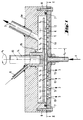
- Figures 1 and 2 show a preferred embodiment of a differential dynamic filter separator, Fig. 2 being a cross-sectional view along line II-II of the separator of Fig. 1.
- An apparatus according to Figures 1 and 2 shows a ring channel differential rotational shearing gap filter separator.
- a feed fluid is fed into the concentrate chamber 4, which is formed by lid 4a and bottom 4b, via the central feed fluid entering means 1, a hollow shaft.
- a rotatable disc 11 In the concentrate chamber 4 there is installed a rotatable disc 11. It forms a gap 12 with the semi-permeable membrane 6. Rotating the disc 11 induces a relative motion of the feed fluid in the gap 12 along the membrane 6, one of the possible effects being in to avoid or diminish clogging of the membrane pores.
- the filtrate chamber 5 of the system is divided into several partial filtrate chambers 51 to 5 n which are arranged in this preferred embodiment as concentric rings in the bottom 4b around the rotational axis 10 of the rotatable disc 11. The suspension that was fed near the middle of the rotatable disc 11 is led to the outer edge of the concentrate chamber 4.
- the feed fluid is concentrated each time when passing a ring channel with a membrane and a connected partial filtrate chamber.
- the different filtrate fluids which are collected in said ring channels 5 are drained by filtrate exiting means 3.
- the different collected filtrate fluids can have different properties, e.g. different concentration of particles.
- the remaining concentrate fluid is expelled by the concentrate exiting means 2.
- the housing of the filter separator is horizontally divided into two parts. Preferably, these two parts are connected by bolts 8 and a sealing 7.
- sensors 13 are provided in each partial filtrate chamber 51, ... , 5 n or the outlet conduit 3 thereof. These sensors 13 may e.g. be flow rate sensors, concentration sensors, pH sensors, viscosity sensors, pressure sensors.
- the filter separator may also in a further embodiment have radial sectors of membrane portions with different properties instead of the ring channel arrangements of Figure 1. Several membranes can thus be installed and tested under the same circumstances.
Landscapes
- Chemical & Material Sciences (AREA)
- Chemical Kinetics & Catalysis (AREA)
- Engineering & Computer Science (AREA)
- Water Supply & Treatment (AREA)
- Separation Using Semi-Permeable Membranes (AREA)
- Centrifugal Separators (AREA)
- Amplifiers (AREA)
- Oscillators With Electromechanical Resonators (AREA)
Applications Claiming Priority (2)
| Application Number | Priority Date | Filing Date | Title |
|---|---|---|---|
| DE4207614A DE4207614C1 (fr) | 1992-03-10 | 1992-03-10 | |
| DE4207614 | 1992-03-10 |
Publications (2)
| Publication Number | Publication Date |
|---|---|
| EP0560281A1 true EP0560281A1 (fr) | 1993-09-15 |
| EP0560281B1 EP0560281B1 (fr) | 1996-09-18 |
Family
ID=6453706
Family Applications (1)
| Application Number | Title | Priority Date | Filing Date |
|---|---|---|---|
| EP93103753A Expired - Lifetime EP0560281B1 (fr) | 1992-03-10 | 1993-03-09 | Séparateur à filtre dynamique |
Country Status (5)
| Country | Link |
|---|---|
| US (1) | US5415781A (fr) |
| EP (1) | EP0560281B1 (fr) |
| JP (1) | JPH067647A (fr) |
| AT (1) | ATE142896T1 (fr) |
| DE (2) | DE4207614C1 (fr) |
Cited By (1)
| Publication number | Priority date | Publication date | Assignee | Title |
|---|---|---|---|---|
| EP0902723A4 (fr) * | 1995-11-27 | 1999-07-21 | Membrex Inc | Dispositif de filtration a disques rotatifs immerges |
Families Citing this family (24)
| Publication number | Priority date | Publication date | Assignee | Title |
|---|---|---|---|---|
| US5679249A (en) * | 1991-12-24 | 1997-10-21 | Pall Corporation | Dynamic filter system |
| US6117322A (en) * | 1993-06-23 | 2000-09-12 | Pall Corporation | Dynamic filter system |
| DE4340218C1 (de) * | 1993-11-25 | 1994-09-22 | Enderle Guenther Dipl Ing Fh | Filtervorrichtung |
| US5897771A (en) * | 1994-09-14 | 1999-04-27 | Able Co., Ltd. | Apparatus for aerobic treatment of waste water |
| US5476586A (en) * | 1994-12-29 | 1995-12-19 | A+ Corp | Housing for sheet of phase-separating material |
| US5614093A (en) * | 1995-08-23 | 1997-03-25 | Aerojet-General Corporation | Discrete pore platelet filter manufactured by electropolishing |
| US5772879A (en) * | 1995-12-11 | 1998-06-30 | Jaikaran; Allan | Self-cleaning fluid strainer |
| FI106298B (sv) * | 1996-03-04 | 2001-01-15 | Valmet Flootek Oy | Separationsförfarande och -anordning |
| DE19649661A1 (de) * | 1996-11-29 | 1998-06-04 | Pall Corp | Maischeverfahren |
| US6916425B2 (en) | 1996-11-29 | 2005-07-12 | Pall Corporation | Mashing process |
| US5919376A (en) * | 1997-06-10 | 1999-07-06 | Cae Ransohoff Inc. | Filtration apparatus and method |
| GB2365511B (en) * | 1997-07-16 | 2002-03-27 | Pall Corp | Valves for filters |
| AUPP081397A0 (en) | 1997-12-09 | 1998-01-08 | Mcgrath, Kevin Douglas | Filtration apparatus |
| DE10014586C1 (de) * | 2000-03-27 | 2001-10-18 | Guenter Slowik | Verfahren und Vorrichtung zur dynamischen Filtration |
| WO2005053824A2 (fr) | 2003-12-07 | 2005-06-16 | Ben-Gurion University Of The Negev Research And Development Authority | Procede et systeme pour augmenter la recuperation et empecher l'encrassement de precipitation dans des processus a membrane soumise a pression |
| KR100501524B1 (ko) * | 2004-03-11 | 2005-07-18 | 주식회사 환경비젼이십일 | 와류 발생용 로터 및 이를 채용한 여과장치 |
| US7276155B1 (en) * | 2006-05-04 | 2007-10-02 | Wastewater Technology, Inc. | Waste treatment apparatus with integral membrane apparatus |
| JP4929269B2 (ja) * | 2008-11-13 | 2012-05-09 | 三菱重工業株式会社 | 膜容器 |
| US20140318230A1 (en) * | 2013-04-26 | 2014-10-30 | Pall Corporation | Stirrer cell module and method of using |
| WO2015066803A1 (fr) * | 2013-11-08 | 2015-05-14 | Hugues Wanlin | Système rotatif à vide et tamis et procédés de séparation de solides et liquides |
| US10646828B2 (en) | 2014-05-08 | 2020-05-12 | Georgia Tech Research Corporation | Cyclic filtration system |
| WO2016131071A2 (fr) * | 2015-02-19 | 2016-08-25 | Next Generation Analytics Gmbh | Dispositif et procede de filtration |
| CN111916656B (zh) * | 2020-07-21 | 2025-05-13 | 合肥通用机械研究院有限公司 | 一种用于三元材料的集成式生产系统 |
| US20230103973A1 (en) * | 2021-09-24 | 2023-04-06 | Hamilton Sundstrand Corporation | Passive phase separator with liquid removal chamber |
Citations (2)
| Publication number | Priority date | Publication date | Assignee | Title |
|---|---|---|---|---|
| EP0238335A2 (fr) * | 1986-03-20 | 1987-09-23 | Toray Industries, Inc. | Appareil pour plasmaphérèse |
| WO1992021426A1 (fr) * | 1991-05-30 | 1992-12-10 | Membrex, Inc. | Dispositif de filtration a disques rotatifs |
Family Cites Families (9)
| Publication number | Priority date | Publication date | Assignee | Title |
|---|---|---|---|---|
| US2784843A (en) * | 1954-08-10 | 1957-03-12 | American Viscose Corp | Filter construction |
| US3631654A (en) * | 1968-10-03 | 1972-01-04 | Pall Corp | Gas purge device |
| US3499533A (en) * | 1968-11-19 | 1970-03-10 | American Nat Bank & Trust | Automatically cleaned,pivotable,filter assembly |
| US3838774A (en) * | 1973-01-02 | 1974-10-01 | N Ball | Apparatus for monitoring water purification system |
| US3984317A (en) * | 1975-06-05 | 1976-10-05 | Artisan Industries Inc. | Apparatus and process for continuous concentration and washing of solids from a solids-containing fluid |
| US4303522A (en) * | 1978-05-15 | 1981-12-01 | Ducasse Joseph C V | Continuous separation system |
| JPS61178900A (ja) * | 1985-01-22 | 1986-08-11 | 三菱重工業株式会社 | ロ−デイングア−ム緊急液抜き装置 |
| JPH0236359B2 (ja) * | 1985-12-23 | 1990-08-16 | Fukuda Kinzoku Hakufun Kogyo Kk | Kokodokojinseifeecokinikumorigokin |
| DE3803886A1 (de) * | 1988-02-09 | 1989-08-10 | Geesthacht Gkss Forschung | Vorrichtung zum filtern und trennen von stroemungsmedien |
-
1992
- 1992-03-10 DE DE4207614A patent/DE4207614C1/de not_active Expired - Fee Related
-
1993
- 1993-03-09 US US08/029,049 patent/US5415781A/en not_active Expired - Fee Related
- 1993-03-09 EP EP93103753A patent/EP0560281B1/fr not_active Expired - Lifetime
- 1993-03-09 DE DE69304744T patent/DE69304744T2/de not_active Expired - Fee Related
- 1993-03-09 AT AT93103753T patent/ATE142896T1/de active
- 1993-03-10 JP JP5049423A patent/JPH067647A/ja active Pending
Patent Citations (2)
| Publication number | Priority date | Publication date | Assignee | Title |
|---|---|---|---|---|
| EP0238335A2 (fr) * | 1986-03-20 | 1987-09-23 | Toray Industries, Inc. | Appareil pour plasmaphérèse |
| WO1992021426A1 (fr) * | 1991-05-30 | 1992-12-10 | Membrex, Inc. | Dispositif de filtration a disques rotatifs |
Cited By (1)
| Publication number | Priority date | Publication date | Assignee | Title |
|---|---|---|---|---|
| EP0902723A4 (fr) * | 1995-11-27 | 1999-07-21 | Membrex Inc | Dispositif de filtration a disques rotatifs immerges |
Also Published As
| Publication number | Publication date |
|---|---|
| JPH067647A (ja) | 1994-01-18 |
| DE69304744D1 (de) | 1996-10-24 |
| DE4207614C1 (fr) | 1993-09-23 |
| EP0560281B1 (fr) | 1996-09-18 |
| US5415781A (en) | 1995-05-16 |
| ATE142896T1 (de) | 1996-10-15 |
| DE69304744T2 (de) | 1997-01-30 |
Similar Documents
| Publication | Publication Date | Title |
|---|---|---|
| EP0560281B1 (fr) | Séparateur à filtre dynamique | |
| EP0165992B1 (fr) | Appareil et procede de filtrage | |
| US4790942A (en) | Filtration method and apparatus | |
| US4911847A (en) | Process for controlling the permeate composition in a rotary filtration device | |
| JP3577460B2 (ja) | 軸力の減少手段を備えた回転円板型濾過装置 | |
| EP0586591B1 (fr) | Dispositif de filtration a disques rotatifs | |
| CA2237061C (fr) | Dispositif de filtration a disques rotatifs immerges | |
| Jaffrin | Dynamic filtration with rotating disks, and rotating and vibrating membranes: an update | |
| Jaffrin et al. | A hydrodynamic comparison between rotating disk and vibratory dynamic filtration systems | |
| JP2003506208A (ja) | 遠心加圧式分離器およびその制御方法 | |
| WO1992021425A1 (fr) | Dispositif rotatif de filtrage et element filtrant associe | |
| Ding et al. | High shear skim milk ultrafiltration using rotating disk filtration systems | |
| Maybury et al. | The performance of a scaled down industrial disc stack centrifuge with a reduced feed material requirement | |
| Postlethwaite et al. | Flux and transmission characteristics of a vibrating microfiltration system operated at high biomass loading | |
| WO2011091281A2 (fr) | Dispositifs de filtration à tourbillons améliorés | |
| EP0277660A2 (fr) | Procédé et appareil de filtration | |
| AU2014277687B2 (en) | Method for sized-based cell separation using spinning membrane filtration | |
| Whittington | Fermentation broth clarification techniques | |
| JP2004255283A (ja) | 回転型膜分離装置の濃度制御方法及びその濃度制御装置 | |
| JPH06285389A (ja) | 液液分離用遠心分離装置 | |
| WO2024103186A1 (fr) | Appareil de filtration de fluide et procédés associés | |
| Vyas | CROSSFLOW MICROFILTRATION OF SUSPENSIONS CONTAINING LACTALBUMIN PARTICLES | |
| Hashim et al. | A study on the effect of operating parameters on the cross-flow microfiltration of yeasts | |
| MXPA00008180A (en) | Rotary disc filtration device with means to reduce axial forces | |
| Yelshin | Taking steps to meet the wideranging demand for membranes |
Legal Events
| Date | Code | Title | Description |
|---|---|---|---|
| PUAI | Public reference made under article 153(3) epc to a published international application that has entered the european phase |
Free format text: ORIGINAL CODE: 0009012 |
|
| AK | Designated contracting states |
Kind code of ref document: A1 Designated state(s): AT BE CH DE FR IE IT LI NL |
|
| 17P | Request for examination filed |
Effective date: 19940224 |
|
| 17Q | First examination report despatched |
Effective date: 19950220 |
|
| GRAG | Despatch of communication of intention to grant |
Free format text: ORIGINAL CODE: EPIDOS AGRA |
|
| GRAH | Despatch of communication of intention to grant a patent |
Free format text: ORIGINAL CODE: EPIDOS IGRA |
|
| GRAH | Despatch of communication of intention to grant a patent |
Free format text: ORIGINAL CODE: EPIDOS IGRA |
|
| GRAA | (expected) grant |
Free format text: ORIGINAL CODE: 0009210 |
|
| AK | Designated contracting states |
Kind code of ref document: B1 Designated state(s): AT BE CH DE FR IE IT LI NL |
|
| REF | Corresponds to: |
Ref document number: 142896 Country of ref document: AT Date of ref document: 19961015 Kind code of ref document: T |
|
| ET | Fr: translation filed | ||
| REG | Reference to a national code |
Ref country code: CH Ref legal event code: NV Representative=s name: HEPP, WENGER & RYFFEL AG |
|
| ITF | It: translation for a ep patent filed | ||
| REF | Corresponds to: |
Ref document number: 69304744 Country of ref document: DE Date of ref document: 19961024 |
|
| REG | Reference to a national code |
Ref country code: IE Ref legal event code: FG4D Free format text: 69881 |
|
| PGFP | Annual fee paid to national office [announced via postgrant information from national office to epo] |
Ref country code: AT Payment date: 19970227 Year of fee payment: 5 |
|
| PGFP | Annual fee paid to national office [announced via postgrant information from national office to epo] |
Ref country code: FR Payment date: 19970313 Year of fee payment: 5 |
|
| PGFP | Annual fee paid to national office [announced via postgrant information from national office to epo] |
Ref country code: DE Payment date: 19970314 Year of fee payment: 5 |
|
| PGFP | Annual fee paid to national office [announced via postgrant information from national office to epo] |
Ref country code: CH Payment date: 19970320 Year of fee payment: 5 |
|
| PGFP | Annual fee paid to national office [announced via postgrant information from national office to epo] |
Ref country code: IE Payment date: 19970326 Year of fee payment: 5 |
|
| PGFP | Annual fee paid to national office [announced via postgrant information from national office to epo] |
Ref country code: NL Payment date: 19970327 Year of fee payment: 5 |
|
| PGFP | Annual fee paid to national office [announced via postgrant information from national office to epo] |
Ref country code: BE Payment date: 19970521 Year of fee payment: 5 |
|
| PLBE | No opposition filed within time limit |
Free format text: ORIGINAL CODE: 0009261 |
|
| 26N | No opposition filed | ||
| PG25 | Lapsed in a contracting state [announced via postgrant information from national office to epo] |
Ref country code: IE Free format text: LAPSE BECAUSE OF NON-PAYMENT OF DUE FEES Effective date: 19980309 Ref country code: AT Free format text: LAPSE BECAUSE OF NON-PAYMENT OF DUE FEES Effective date: 19980309 |
|
| PG25 | Lapsed in a contracting state [announced via postgrant information from national office to epo] |
Ref country code: LI Free format text: LAPSE BECAUSE OF NON-PAYMENT OF DUE FEES Effective date: 19980331 Ref country code: FR Free format text: THE PATENT HAS BEEN ANNULLED BY A DECISION OF A NATIONAL AUTHORITY Effective date: 19980331 Ref country code: CH Free format text: LAPSE BECAUSE OF NON-PAYMENT OF DUE FEES Effective date: 19980331 Ref country code: BE Free format text: LAPSE BECAUSE OF NON-PAYMENT OF DUE FEES Effective date: 19980331 |
|
| BERE | Be: lapsed |
Owner name: PALL CORP. Effective date: 19980331 |
|
| PG25 | Lapsed in a contracting state [announced via postgrant information from national office to epo] |
Ref country code: NL Free format text: LAPSE BECAUSE OF NON-PAYMENT OF DUE FEES Effective date: 19981001 |
|
| REG | Reference to a national code |
Ref country code: CH Ref legal event code: PL |
|
| NLV4 | Nl: lapsed or anulled due to non-payment of the annual fee |
Effective date: 19981001 |
|
| PG25 | Lapsed in a contracting state [announced via postgrant information from national office to epo] |
Ref country code: DE Free format text: LAPSE BECAUSE OF NON-PAYMENT OF DUE FEES Effective date: 19981201 |
|
| REG | Reference to a national code |
Ref country code: FR Ref legal event code: ST |
|
| PG25 | Lapsed in a contracting state [announced via postgrant information from national office to epo] |
Ref country code: IT Free format text: LAPSE BECAUSE OF NON-PAYMENT OF DUE FEES;WARNING: LAPSES OF ITALIAN PATENTS WITH EFFECTIVE DATE BEFORE 2007 MAY HAVE OCCURRED AT ANY TIME BEFORE 2007. THE CORRECT EFFECTIVE DATE MAY BE DIFFERENT FROM THE ONE RECORDED. Effective date: 20050309 |