EP0560392A1 - Vorrichtung zur Herstellung und Wickeln eines Riemes - Google Patents
Vorrichtung zur Herstellung und Wickeln eines Riemes Download PDFInfo
- Publication number
- EP0560392A1 EP0560392A1 EP93104090A EP93104090A EP0560392A1 EP 0560392 A1 EP0560392 A1 EP 0560392A1 EP 93104090 A EP93104090 A EP 93104090A EP 93104090 A EP93104090 A EP 93104090A EP 0560392 A1 EP0560392 A1 EP 0560392A1
- Authority
- EP
- European Patent Office
- Prior art keywords
- belt
- shaped member
- taking
- transport section
- unit
- Prior art date
- Legal status (The legal status is an assumption and is not a legal conclusion. Google has not performed a legal analysis and makes no representation as to the accuracy of the status listed.)
- Withdrawn
Links
Images


Classifications
-
- B—PERFORMING OPERATIONS; TRANSPORTING
- B65—CONVEYING; PACKING; STORING; HANDLING THIN OR FILAMENTARY MATERIAL
- B65H—HANDLING THIN OR FILAMENTARY MATERIAL, e.g. SHEETS, WEBS, CABLES
- B65H19/00—Changing the web roll
- B65H19/22—Changing the web roll in winding mechanisms or in connection with winding operations
-
- B—PERFORMING OPERATIONS; TRANSPORTING
- B65—CONVEYING; PACKING; STORING; HANDLING THIN OR FILAMENTARY MATERIAL
- B65H—HANDLING THIN OR FILAMENTARY MATERIAL, e.g. SHEETS, WEBS, CABLES
- B65H2801/00—Application field
- B65H2801/93—Tyres
Definitions
- the present invention relates to a forming and taking-up apparatus in which a belt-shaped member formed by a calender unit is taken up onto a first and a second takeup unit which can be changed over, as necessary.
- This apparatus comprises: a calender unit 13 for coating both upper and lower sides of a cord fabric formed by a multiplicity of reinforcement cords 11 with rubber so as to form a belt-shaped member 12; a cooling unit 15 disposed downstream of this calender unit 13 and having a plurality of cooling drums 14 around which the belt-shaped member 12 discharged from the calender unit 13 is consecutively wound; an accumulation unit 18 disposed downstream of the cooling unit 15 and constituted by a plurality of upper rollers 16 and a plurality of lower rollers 17 which form pairs therewith and are adapted to move vertically, wherein the belt-shaped member 12 which has passed around the cooling drums 14 is consecutively threaded around each of the pairs of upper and lower rollers 16, 17; a guide roller 19 disposed downstream of the accumulation unit 18 and adapted to change the direction of travel of the belt-shaped member 12 which has passed through the accumulation unit 18, to a downward direction
- the operation of the first takeup unit 21 is stopped to stop the taking-up operation of the first takeup unit 21. Then, after cutting the belt-shaped member 12 in the widthwise direction thereof by means of the cutter 20, the first takeup unit 21 is operated again to allow a trailing end of the belt-shaped member 12 to be taken up onto a takeup roll 23 of the first takeup unit 21.
- a liner 25 is paid out from a liner roll 24, and its leading end is wound around the takeup roll 23 in advance.
- a roll 26 of the second takeup unit 22 is moved forward toward the first takeup unit 21, and the liner 25 is caused to project beyond a position of intersection with a perpendicular line including the cutter 20. Then, a leading end of the belt-shaped member 12 is fed onto the liner 25 of the second takeup unit 22, and by operating the second takeup unit 22, the leading end of the belt-shaped member 12 together with the liner 25 is taken up onto the takeup roll 23 of the second takeup unit 22.
- the belt-shaped member 12 is taken up at a speed higher than a normal taking-up speed until the amount of the belt-shaped member 12 accumulated in the accumulation unit 18 becomes normal.
- an apparatus for forming and taking up a belt-shaped member comprising: a calender unit for continuously forming the belt-shaped member; first taking-up means for taking up the formed belt-shaped member and second taking-up means for taking up the belt-shaped member instead of the first taking-up means; cutting means for cutting the belt-shaped member in a widthwise direction thereof; and transporting means for transporting the formed belt-shaped member to the taking-up means.
- the transporting means are comprised of first transporting means including a first transport section disposed between the calender unit and the first taking-up means and extending substantially in a horizontal direction and a second transport section extending substantially in a downward direction from a rear end of the first transport section toward the first taking-up means, and second transporting means including a third transport section which is disposed between the rear end of the first transport section and the second taking-up means and whose front end is spaced apart a predetermined distance from the rear end of the first transport section and a fourth transport section extending toward the second taking-up means from a rear end of the third transport section.
- the apparatus further comprises guiding means for guiding the belt-shaped member from the rear end of the first transport section to the front end of the third transport section when a taking-up operation of the belt-shaped member is changed over from the first taking-up means to the second taking-up means.
- the first to fourth transport sections are preferably provided with a belt conveyor disposed on a frame, respectively.
- the guiding means includes a guide rail laid on the frame, a movable base which is movable along the guide rail, a pair of rollers which are supported rotatably on the movable base and rotate in opposite directions to each other when a conveyor belt of the belt conveyor trained around the pair of rollers moves and one of which constitutes a front end of the belt conveyor, and a moving mechanism for moving the movable base.
- the moving mechanism is adapted to move the movable base toward the rear end of the second transport section to allow the front end of the third transport section to approach the rear end of the first transport section when the taking-up operation of the belt-shaped member is changed over from the first taking-up means to the second taking-up means.
- the apparatus may preferably comprise an accumulation unit which is disposed between the cutting means and the calender unit and includes a guide rail extending in a direction perpendicular to a direction of travel of the belt-shaped member, a sliding member slidably supported on the guide rail and for rotatably supporting a dancer roll around which the belt-shaped member is wound, a piston coupled to the sliding member and adapted to urge the dancer roll in a direction in which the dancer roll moves away from a path of travel of the belt-shaped member, and a cylinder for the piston.
- an accumulation unit which is disposed between the cutting means and the calender unit and includes a guide rail extending in a direction perpendicular to a direction of travel of the belt-shaped member, a sliding member slidably supported on the guide rail and for rotatably supporting a dancer roll around which the belt-shaped member is wound, a piston coupled to the sliding member and adapted to urge the dancer roll in a direction in which the dancer roll moves away from a path
- the cutting means may be provided with moving means for moving the cutting means in the direction of travel of the belt-shaped member at a substantially identical speed to the traveling speed of the belt-shaped member when the belt-shaped member is cut.
- the apparatus can be configured without the accumulation unit.
- the first transport section and the third transport section are preferably disposed with a distance therebetween such as to allow the belt-shaped member to be suspended downward before a leading end of the belt-shaped member reaches the front end of the third transport section from the rear end of the first transport section at times other than when the taking-operation of the belt-shaped member is changed over from the first taking-up means to the second taking-up means.
- the forming and taking-up apparatus in accordance with the present invention may preferably further comprise assisting means for assisting the approach of the belt-shaped member from the rear end of the first transport section toward a front portion of the second transport section when the belt-shaped member is taken up onto the first taking-up means.
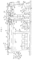
- FIG. 1 shows a conceptual diagram of an embodiment of a forming and taking-up apparatus in accordance with the present invention.
- This apparatus mainly comprises a calender unit 31, a first transporting unit 51, a first takeup unit 55, a second transporting unit 103, a second takeup unit 85, and a guiding unit 110.
- the calender unit 31 is disposed on the upstream side in a transporting direction (i.e., from the left-hand side to the right-hand side in the drawing), and this calender unit 31 has two pairs of calender rolls 32a, 32b, and 32c, 32d, the pairs being spaced apart from each other in a substantially vertical direction.
- a cord fabric formed by a multiplicity of reinforcement cords 33 is fed into a nip between the calender rolls 32b, 32c.
- a rubber material is fed into a nip between the calender rolls 32a, 32b and a nip between the calender rolls 32c, 32d and is formed into rubber sheets.
- the rubber sheets thus formed are attached to both the upper and lower sides of the cords 33, respectively, with a result that rubberized cords, i.e., a belt-shaped member 34, is formed continuously.
- a front frame 37 is disposed in the rear of the calender unit 31 (hereafter, the right-hand side (the downstream side) of the drawing will be called the rear side of the apparatus, and the left-hand side (the upstream side) of the drawing the front side of the apparatus).
- a plurality of, in this case eight, cooling drums 38 are rotatably supported below the front frame 37. After passing around a guide roller 39, the belt-shaped member 34 is consecutively threaded around the outer sides of the cooling drums 38 so as to be cooled.
- two pairs of rollers 40 are rotatably supported on top of the front frame 37, one pair being located on the front side and the other on the rear side.
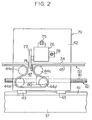
- FIG. 2 shows an enlarged view of a cutter unit 79 disposed movably on the front frame 37.
- a pair of horizontal guide rails 41 extending in the longitudinal direction of the apparatus are laid on the upper surface of the front frame 37.
- Slide bearings 43 attached to the bottom of a movable frame 42 are slidably engaged on these guide rails 41.
- Two pairs of rollers 44a, 44b, and 44c, 44d, which are spaced apart from each other in the longitudinal direction of the apparatus, are rotatably supported by this movable frame 42, a conveyor belt 45 being wound around the aforementioned rollers 40 and the rollers 44a to 44d.
- the conveyor belt 45 transports the belt-shaped member 34 toward the downstream side after the belt-shaped member 34 has passed around the cooling drums 38 and a plurality of guide rollers 46.
- the belt conveyor 45 is curved downward at the positions of these rollers 44a, 44b, 44c, 44d, thereby defining a substantially rectangular space 47. As shown in Fig.
- a roller conveyor 49 constituted by a plurality of small rollers 48 having axes parallel with the axes of the rollers 40 is disposed on the front frame 37 at a position immediately following this conveyor belt 45.
- a shift roller 50 having an axis parallel with the axes of the rollers 40 is rotatably supported on the front frame 37 at a position immediately following this roller conveyor 49.
- the rollers 40, 44a, 44b, 44c, 44d, the conveyor belt 45, the roller conveyor 49, and the shift roller 50 as a whole constitute a first transport section 52 of the first transporting unit 51.
- This first transport section 52 extends in the longitudinal direction of the apparatus, and transports the belt-shaped member 34 in the rearward direction.
- the first takeup unit 55 is disposed downstream of the calender unit 31 and below the shift roller 50.
- This first takeup unit 55 is rotatably supported by a support base 56, and has a takeup roll 57 which is rotatively driven by an unillustrated motor.
- a liner roll 59 around which a liner 58 has been wound is rotatably supported above the support base 56.
- the liner 58 paid out from this liner roll 59 passes around a plurality of guide rollers 60, and is then taken up onto the takeup roll 57.
- a final guide roller 60a is located rearwardly of the takeup roll 57, the liner 58 is taken up onto the takeup roll 57 while traveling toward the calender unit 31.
- Two rollers 63 which are spaced apart from each other in the vertical direction, are rotatably supported on the front frame 37 at positions below the aforementioned shift roller 50.
- a conveyor belt 65 extending substantially downward from the shift roller 50 toward the first takeup unit 55 is trained between these rollers 63 and around a plurality of guide rollers 64 supported rotatably by the front frame 37.
- this conveyor belt 65 travels in the direction of the arrow at the same speed as that of the conveyor belt 45 so as to substantially downwardly transport the belt-shaped member 34, which has undergone a shift in direction by passing around the shift roller 50 located at the rear end of the first transport section 52.
- Reference numeral 66 denotes an inclined conveyor which extends diagonally from a vicinity of a lower end of the conveyor belt 65 to immediately behind the takeup roll 57.
- This inclined conveyor 66 is driven by the unillustrated motor so as to transport the belt-shaped member 34, which has passed along the conveyor belt 65, at the same speed as that of the conveyor belt 65 and feed the same to the takeup roll 57.
- the belt-shaped member 34 together with the liner 58 is taken up onto the takeup roll 57.
- the aforementioned rollers 63, guide rollers 64, conveyor belt 65, and inclined conveyor 66 as a whole constitute a second transport section 67 extending substantially downward from the rear end of the first transport section 52 toward the first takeup unit 55.
- the inclined conveyor 66 may not be provided, in which case the conveyor belt 65 is extended up to a vicinity of the liner 58 of the first takeup unit 55.
- the second transport section 67 and the first transport section 52 constitute the aforementioned first transporting unit 51 disposed between the calender unit 31 and the first takeup unit 55.
- This first transporting unit 51 is capable of transporting the belt-shaped member 34 formed by the calender unit 31 up to the first takeup unit 55.
- a pushing conveyor 70 is disposed in the rear of the first transport section 52 and adapted to travel at the same speed as the conveyor belt 65.
- This pushing conveyor 70 is adapted to push the belt-shaped member 34 being transported by the conveyor belt 65 against the conveyor belt 65.
- a swing arm 72 having a pressing roller 71, serving as a direction-shifting means, is mounted above the pushing conveyor 70.
- this swing arm 72 with the pressing roller is not required since such a belt-shaped member droops down by its own weight.
- the swing arm 72 with the pressing roller is effective in bending the belt-shaped member 34 downward from the roller 50.
- a nozzle adapted to inject air in the downward direction from above may be mounted at the position of the swing arm 72 so as to downwardly direct the belt-shaped member 34 projecting rearwardly from the roller 50.
- a horizontal lower blade 74 extending in the widthwise direction of the belt-shaped member 34 is mounted on the movable frame 42.
- This lower blade 74 is located within the space 47 immediately below the belt-shaped member 34 being transported by the conveyor belt 45.
- a guide rail 75 parallel with the lower blade 74 is fixed in the movable frame 42, and a carriage 76 located above the lower blade 74 and above the belt-shaped member 34 is slidably supported on this guide rail 75.
- a disc-like upper blade 77 is supported by this carriage 76 in such a manner as to be rotatable and vertically movable. This upper blade 77 is rotatively driven by an unillustrated motor incorporated in the carriage 76.
- a screw shaft 78 parallel with the guide rail 75 is screwed into the carriage 76, and this screw shaft 78 is rotatively driven by an unillustrated motor.
- the screw shaft 78 rotates with the upper blade 77 rotating, and the carriage 76 is thereby moved along the guide rail 75 in the widthwise direction of the belt-shaped member 34, the belt-shaped member 34 is cut in the widthwise direction by the upper blade 77 at its lowered position and the lower blade 74.
- the aforementioned movable frame 42, lower blade 74, guide rail 75, carriage 76, upper blade 77, and screw shaft 78 as a whole constitute the cutter unit 79 disposed in the first transport section 52 of the first transporting unit 51 and capable of cutting the belt-shaped member 34 in the widthwise direction.
- a threaded member 80 is mounted in the movable frame 42 of this cutter unit 79, and a screw shaft 81, which is disposed in parallel with the guide rail 41 and is rotatively driven by an unillustrated motor, is screwed into the threaded member 80.
- the cutter unit 79 moves in the direction of travel, i.e., in the rearward direction (to the downstream side) at the same speed as the traveling speed of the belt-shaped member 34, so that the cutting of the belt-shaped member 34 by the cutter unit 79 is effected in a state in which the relative speed of the belt-shaped member 34 vis-a-vis the speed of the cutter unit 79 is zero.
- the aforementioned guide rails 41, slide bearings 43, threaded member 80, and screw shaft 81 as a whole constitute a moving unit 82 for moving the cutter unit 79 in the direction of travel at the same speed as the traveling speed of the belt-shaped member 34 when the belt-shaped member 34 is cut.
- the second takeup unit 85 is disposed in the rear of the first takeup unit 55.
- this second takeup unit 85 has a support base 86, a takeup roll 87, and a liner roll 88.
- a liner 89 paid out from this liner roll 88 passes around a plurality of guide rollers 90, and is then taken up onto the takeup roll 87 while traveling from the rear side toward the front side.
- reference numeral 93 denotes a rear frame disposed in the rear of the front frame 37 in such a manner as to surround the second takeup unit 85.
- a pair of guide rails 94 extending in the longitudinal direction of the apparatus are laid on top of this rear frame 93.
- Numeral 95 denotes a movable base in a lower portion of which slide bearings 96 slidably engage on the guide rails 94.
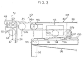
- Fig. 3 shows an enlarged view of this movable base 95 and its vicinity.
- a roller 97a and a roller 97b are rotatably supported on a front-end upper portion of this movable base 95 and on a rear-end lower portion thereof, respectively.
- a roller 97c and a roller 97d are rotatably supported on a front-end upper portion of the rear frame 93 located substantially immediately below the roller 97a and in a rear-end upper portion of the rear frame 93 at the same height of the roller 97a, respectively. Furthermore, a roller 97e and a roller 97f are rotatably supported on a rear-end lower portion of the rear frame 93 immediately below the roller 97d and in a rear-end central portion of the frame 93 between the roller 97d and the roller 97e, respectively.
- a conveyor belt 98 is trained around these rollers 97a, 97d, 97e, 97f, 97c, 97b.
- the conveyor belt 98 is made to travel in the direction of the arrow, so as to transport the belt-shaped member 34, fed from the first transport section 52 of the first transporting unit 51, toward the second takeup unit 85.
- Upper surfaces of the rollers 97a, 97d are located at positions slightly lower than an upper surface of the shift roller 50, as shown in Figs. 1 and 3, so as to facilitate the transfer of the belt-shaped member 34 from the first transport section 52.
- roller 97a and the roller 97d are spaced apart from each other in the longitudinal direction of the apparatus at the same height, and the roller 97d and the roller 97e are vertically spaced apart from each other, as described before, a portion of the conveyor belt 98 between the rollers 97a and 97d extends in the longitudinal direction of the apparatus, while a portion of the conveyor belt 98 between the rollers 97d and 97e extends substantially vertically.
- Numeral 99 denotes an inclined conveyor which extends diagonally from a vicinity of a lower end of the conveyor belt 98 to immediately behind the takeup roll 87.
- This inclined conveyor 99 is driven by the unillustrated motor so as to transport the belt-shaped member 34, which has passed along the conveyor belt 98, at the same speed as that of the conveyor belt 98 and feed the same to the takeup roll 87.
- the first and second transport sections are arranged with a distance therebetween such as to allow the leading end of the belt-shaped member to droop down before it reaches the front end of the third transport section from the rear end of the first transport section. Accordingly, this distance is adjusted, as required, depending on the type of material transported.
- the aforementioned third and fourth transport sections 101, 102 as a whole constitute the second transporting unit 103 which is disposed between the first transport 52 of the first transporting unit 51 and the second takeup unit 85 and is capable of transporting the belt-shaped member 34, delivered from the first transport section 52 of the first transporting unit 51, up to the second takeup unit 85.
- Reference numeral 105 denotes a pushing conveyor which is disposed in the rear of the rear frame 93 and travels at the same speed as that of the conveyor belt 98. This pushing conveyor 105 is brought into close contact with the portion of the conveyor belt 98 located in the fourth transport section 102. As the pushing conveyor 105 pushes the belt-shaped member 34 being transported by the conveyor belt 98 against the conveyor belt 98, the pushing conveyor 105 shifts the direction of the belt-shaped member 34 to the downward direction at the position of the roller 97d, and at the same time prevents the trailing end thereof from falling down.
- a cylinder 106 is mounted on top of the rear frame 93 and extends in the longitudinal direction of the apparatus.
- a distal end of a piston rod 107 of this cylinder 106 is coupled to a lower portion of the movable base 95.
- the movable base 95 moves toward the front in such a manner as to approach the rear end of the first transport section 52 of the first transporting unit 51, i.e., the shift roller 50, and the roller 97a moves from the standby position T indicated by the solid lines in Fig. 3 up to a guiding position Y indicated by the phantom lines.
- the conveyor belt 98 When the roller 97a thus moves toward the front, the conveyor belt 98 is extended toward the front, and an extended portion 98a of the conveyor belt 98 bridges the first transport section 52 of the first transporting unit 51 and the third transport section 101 of the second transporting unit 103 (i.e., the portion of the conveyor belt 98 between the roller 97a at the standby position T and the roller 97d).
- the conveyor belt 98 is capable of guiding the belt-shaped member 34, released from the rear end of the first transport section 52, up to the third transport section 101.
- the aforementioned movable base 95, the extended portion 98a of the conveyor belt 98, and the cylinder 106 as a whole constitute the guiding unit 110 for guiding the belt-shaped member 34 from the rear end of the first transport section 52 of the first transporting unit 51 up to the front end of the third transport section 101 of the second transporting unit 103 only when the belt-shaped member 34 is taken up onto the second takeup unit 85.
- the belt-shaped member 34 is continuously formed as rubber sheets formed by the calender rolls 32a, 32b and 32c, 32d are respectively attached to the upper and lower sides of the cords 33 fed into a nip between the calender rolls 32b, 32c. After the belt-shaped member 34 thus formed is cooled by the cooling drums 38, the belt-shaped member 34 is transported to the first takeup unit 55 by the first transporting unit 51, and is taken up onto the takeup roll 57 of the first takeup unit 55 together with the liner 58.
- the taking-up operation of the belt-shaped member 34 is changed over from the first takeup unit 55 to the second takeup unit 85.
- the movable frame 42 remains at a standby position indicated by the solid lines in Fig. 1, the pressing roller 71 is at its raised position, and the roller 97a is at the guiding position Y shown in Fig. 3.
- the belt-shaped member 34 being transported is cut in the widthwise direction thereof by the cutter unit 79 as follows: Namely, the screw shaft 81 (shown in Fig. 2) is rotated by operating the motor, and the cutter unit 79 is moved in the direction of travel at the same speed as the traveling speed of the belt-shaped member 34.
- the screw shaft 78 is rotated by the motor to move the carriage 76 along the guide rail 75, and the upper blade 77, which is at its lowered position and is in contact with the lower blade 74, is rotated by the motor.
- the belt-shaped member 34 is cut in the widthwise direction thereof at a predetermined position by means of the upper and lower blades 77, 74. If the belt-shaped member 34 is cut in the state in which the relative speed thereof vis-a-vis the speed of the cutter unit 79 is zero, it is unnecessary to stop the traveling of the belt-shaped member 34 during cutting. Accordingly, if the combination adopted in this embodiment is used, it becomes possible to eliminate the accumulation unit.
- the conveyor belt 98 and the pushing conveyor 105 are made to travel at the same speed by operating the motor, and the leading end of the liner 89 paid out from the liner roll 88 is taken up onto the takeup roll 87.
- the leading end of the belt-shaped member 34 reaches the rear end of the first transport section 52, this leading end projects substantially in the horizontal direction from the shift roller 50 toward the rear owing to the rigidity of the belt-shaped member 34, as indicated by the phantom lines in Fig. 3.
- the extended portion 98 of the conveyor belt 98 is at a position slightly lower than that of the first transport section 52, and bridges the first transport section 52 of the first transporting unit 51 and the third transport section 101 of the second transporting unit 103.
- the leading end of the belt-shaped member 34 projecting rearwardly from the shift roller 50 rides onto the extended portion 98a of the conveyor belt 98
- the leading end of the belt-shaped member 34 is guided to the third transport section 101 of the second transporting unit 103.
- the leading end of the belt-shaped member 34 is transported in the rearward direction by the third transport section 101, and upon reaching the rear end of the third transport section 101, i.e., the roller 97d, the leading end of the belt-shaped member 34 undergoes a shift in the direction to the downward direction.
- the leading end of the belt-shaped member 34 is transported substantially in the downward direction while being nipped by the pushing conveyor 105 and the fourth transport section 102, and is further transported diagonally toward the front by means of the inclined conveyor 99 before it is taken up onto the takeup roll 87.
- the leading end of the belt-shaped member 34 is taken up onto the takeup roll 87 of the second takeup unit 85.
- the movable base 95 moves in the rearward direction, so that the roller 97a moves up to the standby position T indicated by the solid lines in Fig. 3.
- the taking-up operation of the belt-shaped member 34 is changed over from the first takeup unit 55 to the second takeup unit 85, and the belt-shaped member 34 is then transported by the first transport section 52 of the first transporting unit 51, guiding unit 110, and the third and fourth transport sections 101, 102 of the second transporting unit 103.
- the belt-shaped member 34 is then fed to the second takeup unit 85 so as to be consecutively taken up thereby. Meanwhile, the trailing end of the belt-shaped member 34, after being transported by the second transport section 67 of the first transporting unit 51, is taken up onto the first takeup unit 55, and this completes the taking-up operation by the first takeup unit 55.
- the taking-up operation of the belt-shaped member 34 is changed over from the second takeup unit 85 to the first takeup unit 55.
- the belt-shaped member 34 is cut in the widthwise direction thereof by the cutter unit 79 in the state in which the relative speed is zero.
- a space with a predetermined distance is formed between the front end of the third transport section 101 and the rear end of the first transport section 52.
- the leading end of the cut belt-shaped member 34 reaches the rear end of the first transport section 52 and projects rearwardly from the rear end of the first transport section 52, the leading end of the belt-shaped member 34 cannot reach the front end of the third transport section 101 of the second transporting unit 103. Hence, the leading end of the belt-shaped member 34 droops down by its own weight and is transported by the second transport section 67 of the first transporting unit 51.
- the arrangement provided is such that immediately before the leading end of the belt-shaped member 34 reaches the rear end of the first transport section 52, the swing arm 72 is swung downward to cause the pressing roller 71 to press the leading end of the belt-shaped member 34 against the shift roller 50, thereby assisting the bending downward of the belt-shaped member 34.
- the leading end of the belt-shaped member 34 thus bent downward is then guided into the nip between the pushing conveyor 70 and the conveyor belt 65, and is transported while being nipped by the same on both sides thereof.
- the taking-up operation of the belt-shaped member 34 is changed over from the second takeup unit 85 to the first takeup unit 55, and the belt-shaped member 34 is taken up onto the first takeup unit 55.
- the taking-up operation by the second takeup unit 85 is completed when the trailing end of the belt-shaped member 34 is transported to the second takeup unit 85 by the second transporting unit 103 is taken up onto the same.
- the taking-up operation between the first and second takeup units 55, 85 can be changed over instantaneously without temporarily stopping the first and second takeup units 55, 85, i.e., without stopping the traveling of the belt-shaped member 34 in the vicinity of the takeup units. Accordingly, it is possible to make the accumulation unit as compact as possible or to eliminate it, so that the apparatus can be made compact, and the cost of the equipment can be made low.
- Fig. 4 is a diagram illustrating a second embodiment of the present invention.
- the guide rails 41, the screw shaft 81, the motor and the like are omitted, and the cutter unit 120 is fixed on the front frame 37 and is made stationary.
- a compact accumulation unit 121 for accumulating the belt-shaped member 34 during a short period of cutting needs to be disposed between the calender unit 31 and the first transporting unit 51.
- a dancer roll 124 is rotatably supported on a sliding member 123 which is slidably supported on a pair of guide rails extending in a direction perpendicular to the direction of travel of the belt-shaped member 34.
- the belt-shaped member 34 is wound around this dancer roll 124, a piston rod 126 of an air cylinder 125 is coupled to the sliding member 123 by means of a chain 127, whereby the dancer roll 124 is urged with a fixed force in a direction in which the dancer roll 124 moves away from the traveling path of the belt-shaped member 34.
- the guiding unit may be constituted by a swing conveyor adapted to swing about a vicinity of the front end of the third transport section 101 and by a swinging mechanism, e.g., a cylinder, for causing the swing conveyor to swing upward to the horizontal position for bridging the first and third transport sections 52, 101 during guiding, and to swing downward to a suspended position during non-guiding.
- the guiding unit may be constituted by a nozzle disposed downwardly of the rear end of the first transport section between the first and third transport sections 52, 101 and adapted to inject air upwardly from below only during guiding.
- the rear frame 93 and the second takeup unit may be disposed on a base which is slidable in the longitudinal direction of the apparatus via rails and the like by means of a motor or the like.
- this base is moved toward the front, and when it is taken up onto the first takeup unit, the base is moved toward the rear, thereby making it possible to guide the belt-shaped member 34 to either the third or second transport section.
- the accumulation unit can be made as small as possible or can be eliminated, the overall apparatus becomes compact, and the cost of the equipment can be reduced.
Landscapes
- Replacement Of Web Rolls (AREA)
- Casting Or Compression Moulding Of Plastics Or The Like (AREA)
Applications Claiming Priority (2)
| Application Number | Priority Date | Filing Date | Title |
|---|---|---|---|
| JP04089834A JP3128316B2 (ja) | 1992-03-13 | 1992-03-13 | 帯状部材の成形巻取り装置 |
| JP89834/92 | 1992-03-13 |
Publications (1)
| Publication Number | Publication Date |
|---|---|
| EP0560392A1 true EP0560392A1 (de) | 1993-09-15 |
Family
ID=13981797
Family Applications (1)
| Application Number | Title | Priority Date | Filing Date |
|---|---|---|---|
| EP93104090A Withdrawn EP0560392A1 (de) | 1992-03-13 | 1993-03-12 | Vorrichtung zur Herstellung und Wickeln eines Riemes |
Country Status (2)
| Country | Link |
|---|---|
| EP (1) | EP0560392A1 (de) |
| JP (1) | JP3128316B2 (de) |
Families Citing this family (1)
| Publication number | Priority date | Publication date | Assignee | Title |
|---|---|---|---|---|
| JP5425873B2 (ja) * | 2011-11-22 | 2014-02-26 | 住友ゴム工業株式会社 | 未加硫ゴムシートの生産方法 |
Citations (9)
| Publication number | Priority date | Publication date | Assignee | Title |
|---|---|---|---|---|
| US2006499A (en) * | 1933-05-22 | 1935-07-02 | Paper Patents Co | Paper metering, cutting, and reeling |
| US2449234A (en) * | 1947-05-20 | 1948-09-14 | Roofing Machinery Mfg Company | Winder apparatus |
| DE2249367A1 (de) * | 1971-10-11 | 1973-04-26 | Hitachi Ltd | Aufwickelvorrichtung fuer insbesondere duenne metallbaender |
| US3856226A (en) * | 1972-01-10 | 1974-12-24 | Westvaco Corp | Method and apparatus for coreless spool production |
| EP0094784A2 (de) * | 1982-05-15 | 1983-11-23 | General Engineering Radcliffe 1979 Limited | Spulvorrichtung |
| DE3601956A1 (de) * | 1986-01-23 | 1987-07-30 | Maier Christian Masch | Vorrichtung zum aufwickeln von warenbahnen in rollen |
| US4695005A (en) * | 1985-05-13 | 1987-09-22 | Custom Machinery Design, Inc. | Coreless winder for strips of pliable material |
| EP0295230A1 (de) * | 1987-06-12 | 1988-12-14 | Nokia-Maillefer Holding S.A. | Kabelschaltanordnung |
| DE3736755C1 (en) * | 1987-10-30 | 1989-03-30 | Bwg Bergwerk Walzwerk | Device for deflecting a strip, in particular a metal strip, unrolling vertically |
-
1992
- 1992-03-13 JP JP04089834A patent/JP3128316B2/ja not_active Expired - Fee Related
-
1993
- 1993-03-12 EP EP93104090A patent/EP0560392A1/de not_active Withdrawn
Patent Citations (9)
| Publication number | Priority date | Publication date | Assignee | Title |
|---|---|---|---|---|
| US2006499A (en) * | 1933-05-22 | 1935-07-02 | Paper Patents Co | Paper metering, cutting, and reeling |
| US2449234A (en) * | 1947-05-20 | 1948-09-14 | Roofing Machinery Mfg Company | Winder apparatus |
| DE2249367A1 (de) * | 1971-10-11 | 1973-04-26 | Hitachi Ltd | Aufwickelvorrichtung fuer insbesondere duenne metallbaender |
| US3856226A (en) * | 1972-01-10 | 1974-12-24 | Westvaco Corp | Method and apparatus for coreless spool production |
| EP0094784A2 (de) * | 1982-05-15 | 1983-11-23 | General Engineering Radcliffe 1979 Limited | Spulvorrichtung |
| US4695005A (en) * | 1985-05-13 | 1987-09-22 | Custom Machinery Design, Inc. | Coreless winder for strips of pliable material |
| DE3601956A1 (de) * | 1986-01-23 | 1987-07-30 | Maier Christian Masch | Vorrichtung zum aufwickeln von warenbahnen in rollen |
| EP0295230A1 (de) * | 1987-06-12 | 1988-12-14 | Nokia-Maillefer Holding S.A. | Kabelschaltanordnung |
| DE3736755C1 (en) * | 1987-10-30 | 1989-03-30 | Bwg Bergwerk Walzwerk | Device for deflecting a strip, in particular a metal strip, unrolling vertically |
Also Published As
| Publication number | Publication date |
|---|---|
| JPH05254701A (ja) | 1993-10-05 |
| JP3128316B2 (ja) | 2001-01-29 |
Similar Documents
| Publication | Publication Date | Title |
|---|---|---|
| EP1142787B1 (de) | Verfahren und Vorrichtung zum Umhüllen von Gegenständen | |
| EP0427408B1 (de) | Vorrichtung zum kontinuierlichen Aufwickeln von Bahnen | |
| EP0514226A1 (de) | Verfahren und Vorrichtung zum Wickeln einer Bahn | |
| JP4871439B2 (ja) | 個別に運ばれる平坦な物体を重なった形態で前進コンベア上に堆積させる装置 | |
| US3567144A (en) | Apparatus for winding sheet material | |
| EP0519666A2 (de) | System zum Aufwickeln eines bandförmigen Materials | |
| JPH0834549A (ja) | ストリップコンベヤのためのループ緩衝器 | |
| SE451374B (sv) | Anordning for genomforande av en flygande vexling av rullar | |
| JPH0358988B2 (de) | ||
| CN1572487B (zh) | 纸的导向装置 | |
| US4084761A (en) | Roll support assembly | |
| JPS63180661A (ja) | 帯状材料の搬送装置 | |
| KR100353139B1 (ko) | 슬리터 리와인더 | |
| US4934621A (en) | Device for continuously feeding a web of material from a stock roll | |
| CN1123541A (zh) | 从连续循环带上剥离产品的装置 | |
| US4130206A (en) | Sheet piling machine with classifier and multiple piling arrangements | |
| JP3128316B2 (ja) | 帯状部材の成形巻取り装置 | |
| EP4594228A2 (de) | Bahnaufnahme- und -übertragungssystem für ein bahnverarbeitungssystem | |
| JP2001522767A (ja) | ロールを形成するためのシート状連続製品の巻き取り装置 | |
| US3970261A (en) | Handling tire making materials | |
| CN120462994B (zh) | 一种动态协同的卫生用品塑料包装膜加工设备及其加工方法 | |
| JP3194348B2 (ja) | 車の搬送方法および装置 | |
| JPH0618739Y2 (ja) | 走間切断機用切断品取り出し装置 | |
| US3055659A (en) | Sheet piler for handling odd shaped materials | |
| US20040245366A1 (en) | Device for continuous winding of webs |
Legal Events
| Date | Code | Title | Description |
|---|---|---|---|
| PUAI | Public reference made under article 153(3) epc to a published international application that has entered the european phase |
Free format text: ORIGINAL CODE: 0009012 |
|
| AK | Designated contracting states |
Kind code of ref document: A1 Designated state(s): DE ES FR GB IT |
|
| 17P | Request for examination filed |
Effective date: 19931209 |
|
| 18W | Application withdrawn |
Withdrawal date: 19940519 |