EP0560404B1 - Verfahren und Vorrichtung zur Herstellung eines Rohrbündels - Google Patents
Verfahren und Vorrichtung zur Herstellung eines Rohrbündels Download PDFInfo
- Publication number
- EP0560404B1 EP0560404B1 EP93106707A EP93106707A EP0560404B1 EP 0560404 B1 EP0560404 B1 EP 0560404B1 EP 93106707 A EP93106707 A EP 93106707A EP 93106707 A EP93106707 A EP 93106707A EP 0560404 B1 EP0560404 B1 EP 0560404B1
- Authority
- EP
- European Patent Office
- Prior art keywords
- sheath
- bundle
- tubes
- python
- pig
- Prior art date
- Legal status (The legal status is an assumption and is not a legal conclusion. Google has not performed a legal analysis and makes no representation as to the accuracy of the status listed.)
- Expired - Lifetime
Links
Images

Classifications
-
- B—PERFORMING OPERATIONS; TRANSPORTING
- B29—WORKING OF PLASTICS; WORKING OF SUBSTANCES IN A PLASTIC STATE IN GENERAL
- B29C—SHAPING OR JOINING OF PLASTICS; SHAPING OF MATERIAL IN A PLASTIC STATE, NOT OTHERWISE PROVIDED FOR; AFTER-TREATMENT OF THE SHAPED PRODUCTS, e.g. REPAIRING
- B29C63/00—Lining or sheathing, i.e. applying preformed layers or sheathings of plastics; Apparatus therefor
- B29C63/18—Lining or sheathing, i.e. applying preformed layers or sheathings of plastics; Apparatus therefor using tubular layers or sheathings
- B29C63/20—Lining or sheathing, i.e. applying preformed layers or sheathings of plastics; Apparatus therefor using tubular layers or sheathings using pressure difference, e.g. vacuum
-
- B—PERFORMING OPERATIONS; TRANSPORTING
- B67—OPENING, CLOSING OR CLEANING BOTTLES, JARS OR SIMILAR CONTAINERS; LIQUID HANDLING
- B67D—DISPENSING, DELIVERING OR TRANSFERRING LIQUIDS, NOT OTHERWISE PROVIDED FOR
- B67D1/00—Apparatus or devices for dispensing beverages on draught
- B67D1/08—Details
- B67D1/0857—Cooling arrangements
- B67D1/0858—Cooling arrangements using compression systems
- B67D1/0861—Cooling arrangements using compression systems the evaporator acting through an intermediate heat transfer means
- B67D1/0865—Cooling arrangements using compression systems the evaporator acting through an intermediate heat transfer means by circulating a cooling fluid along beverage supply lines, e.g. pythons
- B67D1/0867—Cooling arrangements using compression systems the evaporator acting through an intermediate heat transfer means by circulating a cooling fluid along beverage supply lines, e.g. pythons the cooling fluid being a liquid
-
- F—MECHANICAL ENGINEERING; LIGHTING; HEATING; WEAPONS; BLASTING
- F16—ENGINEERING ELEMENTS AND UNITS; GENERAL MEASURES FOR PRODUCING AND MAINTAINING EFFECTIVE FUNCTIONING OF MACHINES OR INSTALLATIONS; THERMAL INSULATION IN GENERAL
- F16L—PIPES; JOINTS OR FITTINGS FOR PIPES; SUPPORTS FOR PIPES, CABLES OR PROTECTIVE TUBING; MEANS FOR THERMAL INSULATION IN GENERAL
- F16L11/00—Hoses, i.e. flexible pipes
- F16L11/22—Multi-channel hoses
-
- F—MECHANICAL ENGINEERING; LIGHTING; HEATING; WEAPONS; BLASTING
- F16—ENGINEERING ELEMENTS AND UNITS; GENERAL MEASURES FOR PRODUCING AND MAINTAINING EFFECTIVE FUNCTIONING OF MACHINES OR INSTALLATIONS; THERMAL INSULATION IN GENERAL
- F16L—PIPES; JOINTS OR FITTINGS FOR PIPES; SUPPORTS FOR PIPES, CABLES OR PROTECTIVE TUBING; MEANS FOR THERMAL INSULATION IN GENERAL
- F16L59/00—Thermal insulation in general
- F16L59/14—Arrangements for the insulation of pipes or pipe systems
- F16L59/153—Arrangements for the insulation of pipes or pipe systems for flexible pipes
-
- B—PERFORMING OPERATIONS; TRANSPORTING
- B67—OPENING, CLOSING OR CLEANING BOTTLES, JARS OR SIMILAR CONTAINERS; LIQUID HANDLING
- B67D—DISPENSING, DELIVERING OR TRANSFERRING LIQUIDS, NOT OTHERWISE PROVIDED FOR
- B67D2210/00—Indexing scheme relating to aspects and details of apparatus or devices for dispensing beverages on draught or for controlling flow of liquids under gravity from storage containers for dispensing purposes
- B67D2210/00028—Constructional details
- B67D2210/00031—Housing
- B67D2210/00044—Insulation
Definitions
- This invention relates to methods and apparatus for making a python, that is to say a bundle of tubes encased in a foam sheath such as is used for the conveyance of beverages from cellar or cool store to a dispensing point such as a bar or soft drinks counter.
- Such bundles of tubes are required to be of surprisingly substantial length, and are used normally in lengths up to and exceeding 100 metres.
- the tube bundles are sheathed in a foam insulating material so as to maintain their low temperature up to the dispensing point, where they may need "flash” cooling or maybe heating immediately prior to dispensing in order to be served at the correct temperature.
- the tube bundles of "food grade” plastics material for the conveyance of beverages and such additional “service", e.g. coolant tubes such as may be required, are assembled into a bundle and wrapped, usually in a cling-film material.
- the bundles are assembled to particular requirements, some at least being standard or substantially so by virtue of their being widely specified by brewery chains or like enterprises.
- the repaired slit constitutes a continous line of impaired thermal resistance along which condensate forms in considerable quantity.
- the condensate drips from the outer wrapping of the python and has obvious deleterious effects on the structure through which the python passes.
- US-A-4,529,009 discloses a multiple core hose assembly comprising a plurality of discrete hose assemblies, each including a primary hose formed from a flexible synthetic plastics material, having a fluid passage extending generally longitudinally therethrough, and a plurality of generally longitudinally extending recesses adapted to seat secondary hoses; a plurality of secondary hoses formed from a flexible synthetic plastics material, seated in the primary hose recesses, the secondary hoses having fluid passages extending generally longitidunally therethrough in heat transfer relation with the primary hose passage; and a flexible tubular sheath of a thermally insulating material, the primary/secondary hose assemblies being assembled together, side-by-side, with the seated secondary hoses disposed around the primary hose passages, within the sheath.
- the sheath may be expanded during insertion of the hose assemblies, for example by applying a partial vacuum to the exterior of the shea partial vacuum to the exterior of the shea partial vacuum to the exterior of
- the present invention provides such a satisfactory method.
- the invention comprises a method for making a python by inserting a bundle of tubes into an elongate foam sheath and expanding the sheath during insertion of the bundle of tubes to increase the length of sheath which may be applied in a single operation, the sheath being expanded during the insertion of the bundle of tubes by applying an overpressure to the interior of the sheath, characterised in that the leading end of the tube bundle to be inserted into the sheath is attached to a pig for guiding its passage through the sheath and the pig may comprise a bullet shaped member having a rearwardly open cavity into which the leading end of the tube bundle fits, and is thus slightly larger in diameter than the tube bundle.
- the bundle of tubes may be introduced through one end of the sheath via a funnel, and the sheath may be clamped around the funnel.
- the internal diameter of the sheath may be enlarged by 5 mm and even up to 20 mm in some cases.
- the bundle of tubes may be wrapped prior to being inserted into the foam sheath, and may be wrapped continuously with the insertion of the wrapped bundle into the sheath.
- the invention also comprises a python made by a method according to the invention.
- Figure 1 illustrates in cross-section a python as may be used for conveying beverages from a cellar or cold store to a bar in a public house, hotel, restaurant or like establishment.
- the python comprises a bundle of tubes 11 which may be of various sizes and which are usually colour and/or number coded. Larger tubes 10 may be used for circulating water or other coolant.
- the tubes 11 are wrapped in a bundle by for example a cling film wrapping 12 and are encased in a soft, flexible and resilient foam sheath 13 which is in turn wrapped in a protective plastics material outer wrapping 14.
- the tubes 11 are of a food grade polymer material such as polyethylene.
- the present invention provides that pythons as illustrated in Figure 1 can be made in long lengths - 20 or 25 metres is a convenient length of sleeve and several sleeves may be applied at once to make a really long python, say 100 metres long, which is standard, or even longer - with relatively few butt joints between sheath sections.
- the limitation is the available length of sheath material, but in practice, perhaps, it is just not convenient to work in lengths greater than 25 metres of sheath because of space limitations.
- Figure 2 shows the bundle of tubes 11 wrapped in cling film 12 being introduced into a foam sheath 13 which has had its internal diameter expanded as illustrated by the arrows. Once the wrapped bundle is in place, the expansion force is relieved and the foam sheath reverts to its original internal diameter to closely surround and grip the bundle.
- the outer wrapping 14 of Figure 1 can then be applied conventionally.
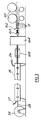
- Figure 3 illustrates diagrammatically an assembly line for python in which the sheath's inner diameter is expanded pneumatically.
- a length of sheath material 13 is placed in a chamber 15 - as illustrated in this is a sealable chamber 15 in the form of a lidded box, the box comprising a base and a lid secured thereto by a piano hinge.
- the sealable box is appropriate to the method covered by parent EP-A-0 328 233; for purposes of the present invention, in which it is not necessary to apply a partial vacuum to the exterior of the sheath, it is unnecessary.
- the sheath protrudes over a funnel which is split into two halves so that it can be applied and removed laterally without threading over an end of the sleeve, for reasons which will become clear later.
- the sheath end is clamped to the funnel e.g. by a hose grip type of clamp.
- the funnel expands the end of the sheath and is pushed sealingly into the aperture in the end enclosure of the box 15.
- the pressure air connection 27 can, before sealing off, be used to blow through the installed sheath 13 a butterfly-type carrier (not shown) for a hauling line 28 which will be attached to haul the bundle of tubes through the sheath.
- the differential pressure from inside to outside the sheath is such as will cause the wall of the sheath to compress and indeed to cause the internal diameter of the sheath 13 to expand by some 5mm, to the condition illustrated in cross-section in Figure 2. In this condition there is no substantial frictional resistance to the passage of the tube bundle through the sheath.
- the diameter of the funnel is chosen appropriately to the diameter of the sheath to ensure good sealing relationship. Different funnel configurations and sizes might be used in connection with the process described herein.
- the leading end of the tube bundle to be inserted in the sheath is attached to a pig 29 for guiding its passage through the sheath.
- the pig 29 is hauled through the sheath by the hauling line or cable 28 which is on a winch 35 situated at the end of the box 15.
- the cable 28 is attached to the end of the bundle of tubes 11 by two stepped locking inserts 32.
- a larger diameter such insert 32a in inserted into a larger tube and a smaller such insert 32b is inserted into a smaller tube 11.
- Hauling wire or cable 28 is introduced into a free end bore of the insert, which is cut away so as to expose a lateral bore aperture through which the hauling wire or cable 28 can be pulled and, to secure the wire or cable, can be knotted.
- the two wires are quickly spliced to become one which passes through there a bore 29a in the nose of the pig 29.
- the pig 29 itself is a bullet shaped member having a rearwardly open cavity into which the leading end of the tube bundle fits.
- the pig 29 is thus slightly larger in diameter than the tube bundle, but not so big as to give rise to excessive frictional drag against the inner wall of the expanded sheath.
- the apparatus illustrated in Figure 3 can conveniently insert a wrapped bundle of tubes into a 20 or 25 meter length of sheath.
- the wrapped tube bundle is inserted serially into two or more, usually four, such lengths of sheath to make a python fifty or one hundred meters in length.
- the finished assembly is then wrapped in a protective cover in the normal way.
- the tube bundle is, as illustrated, assembled continously with the sheathing thereof according to the invention.
- Individual tubes 11 are withdrawn from a creel or drum support arrangment 101 ( Figure 3) through a collecting guide comb 102 and a bundle forming die 103 and from there pass to a cling-film wrapping machine 104 (of conventional type).
- the wrapped bundle is fed from there into the box 15 by a caterpillar-track like belt feeder 105.
Landscapes
- Engineering & Computer Science (AREA)
- General Engineering & Computer Science (AREA)
- Mechanical Engineering (AREA)
- Physics & Mathematics (AREA)
- Thermal Sciences (AREA)
- Manufacturing & Machinery (AREA)
- Packaging Of Annular Or Rod-Shaped Articles, Wearing Apparel, Cassettes, Or The Like (AREA)
- Application Of Or Painting With Fluid Materials (AREA)
- Auxiliary Devices For And Details Of Packaging Control (AREA)
- Container Filling Or Packaging Operations (AREA)
- Electrotherapy Devices (AREA)
- Steering Control In Accordance With Driving Conditions (AREA)
- Lining Or Joining Of Plastics Or The Like (AREA)
- Packages (AREA)
- Basic Packing Technique (AREA)
- Paper (AREA)
- Control Of Eletrric Generators (AREA)
- Bridges Or Land Bridges (AREA)
- Filling Or Discharging Of Gas Storage Vessels (AREA)
- Thermal Insulation (AREA)
- Earth Drilling (AREA)
Claims (6)
- Verfahren zur Herstellung einer Rohrbündelanordnung durch Einführen eines Rohrbündels (11) in eine langgestreckte Schaumstoffhülle (13) und Ausdehnung der Hülle (13) während der Einführung des Rohrbündels, so daß die Länge der Hülle (13), die in einem einzelnen Arbeitsvorgang angewandt werden kann, vergrößert wird, wobei die Hülle (13) während der Einführung des Rohrbündels (11) durch Anlegen eines Überdrucks auf das Innere der Hülle ausgedehnt wird,
dadurch gekennzeichnet,
daß das führende Ende des in die Hülle (13) einzuführenden Rohrbündels zur Lenkung seines Durchgangs durch die Hülle an einem Führungselement (29) befestigt ist, wobei das Führungselement (29) ein geschoßförmiges Element mit einer rückwärtsgewandt offenen Höhlung umfaßt, in welche das führende Ende des Rohrbündels (11) hineinpaßt, und das daher einen geringfügig größeren Durchmesser als das Rohrbündel (11) besitzt. - Verfahren nach Anspruch 1, dadurch gekennzeichnet, daß das Rohrbündel (11) durch ein Ende der Hülle (15) über einen Trichter eingeführt wird, um welchen die Hülle (13) befestigt werden kann.
- Verfahren nach Anspruch 1 oder 2, dadurch gekennzeichnet, daß der innere Durchmesser der Hülle (13) um bis zu 20 mm vergrößert ist.
- Verfahren nach einem der Ansprüche 1 bis 3, dadurch gekennzeichnet, daß das Führungselement (29) durch die Hülle (13) mit einem Seil und einer Winde (28,35) gezogen wird.
- Verfahren nach einem der Ansprüche 1 bis 4, dadurch gekennzeichnet, daß das Rohrbündel (11) nacheinander in zwei oder mehr Längen der Hülle (13) eingeführt wird.
- Rohrbündelanordnung, dadurch gekennzeichnet, daß es durch ein Verfahren nach einem der Ansprüche 1 bis 5 hergestellt wird.
Applications Claiming Priority (3)
| Application Number | Priority Date | Filing Date | Title |
|---|---|---|---|
| GB8801109 | 1988-01-19 | ||
| GB888801109A GB8801109D0 (en) | 1988-01-19 | 1988-01-19 | Protection method & apparatus |
| EP89300119A EP0328233B1 (de) | 1988-01-19 | 1989-01-06 | Schutzverfahren und Vorrichtung |
Related Parent Applications (1)
| Application Number | Title | Priority Date | Filing Date |
|---|---|---|---|
| EP89300119.8 Division | 1989-01-06 |
Publications (2)
| Publication Number | Publication Date |
|---|---|
| EP0560404A1 EP0560404A1 (de) | 1993-09-15 |
| EP0560404B1 true EP0560404B1 (de) | 1995-09-13 |
Family
ID=10630179
Family Applications (2)
| Application Number | Title | Priority Date | Filing Date |
|---|---|---|---|
| EP89300119A Expired - Lifetime EP0328233B1 (de) | 1988-01-19 | 1989-01-06 | Schutzverfahren und Vorrichtung |
| EP93106707A Expired - Lifetime EP0560404B1 (de) | 1988-01-19 | 1989-01-06 | Verfahren und Vorrichtung zur Herstellung eines Rohrbündels |
Family Applications Before (1)
| Application Number | Title | Priority Date | Filing Date |
|---|---|---|---|
| EP89300119A Expired - Lifetime EP0328233B1 (de) | 1988-01-19 | 1989-01-06 | Schutzverfahren und Vorrichtung |
Country Status (6)
| Country | Link |
|---|---|
| EP (2) | EP0328233B1 (de) |
| AT (2) | ATE127889T1 (de) |
| AU (2) | AU4251089A (de) |
| DE (2) | DE68924281T2 (de) |
| ES (1) | ES2050221T3 (de) |
| GB (3) | GB8801109D0 (de) |
Families Citing this family (7)
| Publication number | Priority date | Publication date | Assignee | Title |
|---|---|---|---|---|
| NO174171C (no) * | 1990-06-14 | 1994-03-23 | Norwegian Contractors | Rörbunt beregnet til montering langs en sjöbunn, samt fremgangsmåte til fremstilling av slik rörbunt |
| GB2263746B (en) * | 1992-02-01 | 1995-02-08 | David George Leonard | Seamless pythons |
| GB2328486B (en) * | 1997-08-19 | 1999-06-30 | Colin Brown | Methods and apparatus for making python |
| SG116544A1 (en) * | 2004-05-03 | 2005-11-28 | Ismeca Semiconductor Holding | Method and device for conditioning electronic components into tubes and electronic component outputting device. |
| GB0418206D0 (en) * | 2004-08-14 | 2004-09-15 | Valpar Ind Ltd | "Improvements relating to pythons" |
| EP1626221B1 (de) | 2004-08-14 | 2008-07-23 | Valpar Industrial Limited | Isolierter Schlauchbündel |
| CN100565045C (zh) * | 2007-02-02 | 2009-12-02 | 财团法人工业技术研究院 | 复合式冷媒配管 |
Family Cites Families (13)
| Publication number | Priority date | Publication date | Assignee | Title |
|---|---|---|---|---|
| LU35737A1 (de) * | 1957-01-30 | |||
| US3590855A (en) * | 1969-04-01 | 1971-07-06 | Multiplex Co | Remote-supply liquid dispensing system |
| CH537552A (fr) * | 1970-03-13 | 1973-05-31 | Ipp Ind Polymer Proc S A | Dispositif terminal pour conduite pour fluides |
| IT1089712B (it) * | 1976-12-09 | 1985-06-18 | Mantec Ind Ltd | Metodo per rivestire un tubo |
| US4496499A (en) * | 1980-01-25 | 1985-01-29 | Brittain Perry N | Process for lining high pressure pipeline |
| US4399319A (en) * | 1981-11-18 | 1983-08-16 | Bio-Energy Systems, Inc. | Thermally insulated composite flexible hose |
| JPS58121388A (ja) * | 1982-01-13 | 1983-07-19 | 佐川 志津男 | 管内壁腐蝕防止方法および装置 |
| GB2117504B (en) * | 1982-02-23 | 1985-05-01 | Plascoat Uk Ltd | Multiple core hose |
| US4529009A (en) * | 1983-08-03 | 1985-07-16 | Plascoat U.K. Limited | Multiple core hose |
| SE440043B (sv) * | 1983-10-28 | 1985-07-15 | Sve Dan System Kb | Sett och anordning for att forse en kropp med en relativt tjock beleggning av elastiskt material |
| IT1160147B (it) * | 1983-12-19 | 1987-03-04 | Tubi Italia Spa | Procedimento per la costruzione di un tubo composito comprendente un tubo metallico in particolare un tubo di rame ed un rivestimento di materiale deformabile espanso |
| GB8413964D0 (en) * | 1984-06-01 | 1984-07-04 | Beckett R P | Insulating plastic tubes |
| GB2188695A (en) * | 1986-03-31 | 1987-10-07 | Jr Campbell Hall Steketee | Lining pipes |
-
1988
- 1988-01-19 GB GB888801109A patent/GB8801109D0/en active Pending
-
1989
- 1989-01-06 EP EP89300119A patent/EP0328233B1/de not_active Expired - Lifetime
- 1989-01-06 DE DE68924281T patent/DE68924281T2/de not_active Expired - Fee Related
- 1989-01-06 AT AT93106707T patent/ATE127889T1/de active
- 1989-01-06 EP EP93106707A patent/EP0560404B1/de not_active Expired - Lifetime
- 1989-01-06 AT AT89300119T patent/ATE103055T1/de not_active IP Right Cessation
- 1989-01-06 DE DE68913776T patent/DE68913776T2/de not_active Expired - Fee Related
- 1989-01-06 GB GB8900266A patent/GB2214262B/en not_active Expired - Lifetime
- 1989-01-06 ES ES89300119T patent/ES2050221T3/es not_active Expired - Lifetime
- 1989-10-03 AU AU42510/89D patent/AU4251089A/en active Granted
- 1989-10-03 AU AU42510/89A patent/AU609334B1/en not_active Ceased
-
1990
- 1990-05-25 GB GB9011766A patent/GB2238369B/en not_active Expired - Lifetime
Also Published As
| Publication number | Publication date |
|---|---|
| EP0328233B1 (de) | 1994-03-16 |
| AU4251089A (en) | 1991-04-26 |
| DE68924281T2 (de) | 1996-05-15 |
| AU609334B1 (en) | 1991-04-26 |
| GB2238369B (en) | 1991-09-18 |
| DE68924281D1 (de) | 1995-10-19 |
| GB2214262B (en) | 1991-09-18 |
| GB2238369A (en) | 1991-05-29 |
| EP0560404A1 (de) | 1993-09-15 |
| EP0328233A1 (de) | 1989-08-16 |
| DE68913776T2 (de) | 1994-08-25 |
| ATE103055T1 (de) | 1994-04-15 |
| GB8900266D0 (en) | 1989-03-08 |
| ATE127889T1 (de) | 1995-09-15 |
| GB9011766D0 (en) | 1990-07-18 |
| ES2050221T3 (es) | 1994-05-16 |
| GB8801109D0 (en) | 1988-02-17 |
| GB2214262A (en) | 1989-08-31 |
| DE68913776D1 (de) | 1994-04-21 |
Similar Documents
| Publication | Publication Date | Title |
|---|---|---|
| US6880219B2 (en) | Method of installing Y-branch splittable connector | |
| AU601025B2 (en) | Prelubricated innerduct | |
| AU616778B2 (en) | Transmission line installation | |
| US5863083A (en) | Pulling grip for pre-connectorized fiber optic cable | |
| EP0560404B1 (de) | Verfahren und Vorrichtung zur Herstellung eines Rohrbündels | |
| US5813106A (en) | Method and apparatus for manufacturing and laying out an umbilical | |
| US5421501A (en) | Method and apparatus for cable dispensing and placement | |
| US12019294B2 (en) | Fibre optic cable, methods of manufacture and use thereof | |
| US4331322A (en) | Cable laying apparatus | |
| GB2166833A (en) | Insulating pipe bundle | |
| US20130133773A1 (en) | Multi-Hole Insulation Tube | |
| US3876487A (en) | Apparatus for manufacturing waterproof cable | |
| US2676389A (en) | Method of applying metal sheaths to electric cables | |
| AU664376B2 (en) | Empty conduit with detachable cable assembly and method of making same | |
| US5412858A (en) | Method of encasing bundles of tubes | |
| US5676892A (en) | Installation and method for manufacture of an optical fiber cable | |
| US6546183B2 (en) | Elongated protective profile for protecting a cable installed in an installation channel and an apparatus for installing the profile | |
| US6246820B1 (en) | Device for placing a structural element in a cable installation conduit in order to sub-divide it | |
| KR102115343B1 (ko) | 케이블 보호 튜브관과 그 제조장치 및 제조방법 | |
| CA2154077A1 (en) | Flame-retardant cable tubing bundle | |
| US5127630A (en) | Method for drawing cables into a pipe | |
| JPS5994703A (ja) | 通信ケ−ブル及びその製造方法 | |
| JPH09166735A (ja) | 空気圧送引込み用ケーブル | |
| IE56305B1 (en) | Automated process for insulating plastic tubes | |
| GB2208701A (en) | A dispensing system for alcoholic drinks |
Legal Events
| Date | Code | Title | Description |
|---|---|---|---|
| PUAI | Public reference made under article 153(3) epc to a published international application that has entered the european phase |
Free format text: ORIGINAL CODE: 0009012 |
|
| 17P | Request for examination filed |
Effective date: 19930430 |
|
| AC | Divisional application: reference to earlier application |
Ref document number: 328233 Country of ref document: EP |
|
| AK | Designated contracting states |
Kind code of ref document: A1 Designated state(s): AT BE CH DE ES FR GB GR IT LI LU NL SE |
|
| 17Q | First examination report despatched |
Effective date: 19940407 |
|
| GRAA | (expected) grant |
Free format text: ORIGINAL CODE: 0009210 |
|
| AC | Divisional application: reference to earlier application |
Ref document number: 328233 Country of ref document: EP |
|
| AK | Designated contracting states |
Kind code of ref document: B1 Designated state(s): AT BE CH DE ES FR GB GR IT LI LU NL SE |
|
| PG25 | Lapsed in a contracting state [announced via postgrant information from national office to epo] |
Ref country code: NL Free format text: LAPSE BECAUSE OF FAILURE TO SUBMIT A TRANSLATION OF THE DESCRIPTION OR TO PAY THE FEE WITHIN THE PRESCRIBED TIME-LIMIT Effective date: 19950913 Ref country code: LI Effective date: 19950913 Ref country code: IT Free format text: LAPSE BECAUSE OF FAILURE TO SUBMIT A TRANSLATION OF THE DESCRIPTION OR TO PAY THE FEE WITHIN THE PRE;WARNING: LAPSES OF ITALIAN PATENTS WITH EFFECTIVE DATE BEFORE 2007 MAY HAVE OCCURRED AT ANY TIME BEFORE 2007. THE CORRECT EFFECTIVE DATE MAY BE DIFFERENT FROM THE ONE RECORDED.SCRIBED TIME-LIMIT Effective date: 19950913 Ref country code: GR Free format text: LAPSE BECAUSE OF FAILURE TO SUBMIT A TRANSLATION OF THE DESCRIPTION OR TO PAY THE FEE WITHIN THE PRESCRIBED TIME-LIMIT Effective date: 19950913 Ref country code: ES Free format text: THE PATENT HAS BEEN ANNULLED BY A DECISION OF A NATIONAL AUTHORITY Effective date: 19950913 Ref country code: CH Effective date: 19950913 Ref country code: BE Effective date: 19950913 |
|
| REF | Corresponds to: |
Ref document number: 127889 Country of ref document: AT Date of ref document: 19950915 Kind code of ref document: T |
|
| REF | Corresponds to: |
Ref document number: 68924281 Country of ref document: DE Date of ref document: 19951019 |
|
| PG25 | Lapsed in a contracting state [announced via postgrant information from national office to epo] |
Ref country code: SE Effective date: 19951213 |
|
| PG25 | Lapsed in a contracting state [announced via postgrant information from national office to epo] |
Ref country code: LU Free format text: LAPSE BECAUSE OF NON-PAYMENT OF DUE FEES Effective date: 19960131 |
|
| ET | Fr: translation filed | ||
| REG | Reference to a national code |
Ref country code: CH Ref legal event code: PL |
|
| NLV1 | Nl: lapsed or annulled due to failure to fulfill the requirements of art. 29p and 29m of the patents act | ||
| PLBE | No opposition filed within time limit |
Free format text: ORIGINAL CODE: 0009261 |
|
| 26N | No opposition filed | ||
| PGFP | Annual fee paid to national office [announced via postgrant information from national office to epo] |
Ref country code: GB Payment date: 20000120 Year of fee payment: 12 |
|
| PGFP | Annual fee paid to national office [announced via postgrant information from national office to epo] |
Ref country code: FR Payment date: 20000214 Year of fee payment: 12 Ref country code: AT Payment date: 20000214 Year of fee payment: 12 |
|
| PGFP | Annual fee paid to national office [announced via postgrant information from national office to epo] |
Ref country code: DE Payment date: 20000228 Year of fee payment: 12 |
|
| PG25 | Lapsed in a contracting state [announced via postgrant information from national office to epo] |
Ref country code: GB Free format text: LAPSE BECAUSE OF NON-PAYMENT OF DUE FEES Effective date: 20010106 Ref country code: AT Free format text: LAPSE BECAUSE OF NON-PAYMENT OF DUE FEES Effective date: 20010106 |
|
| GBPC | Gb: european patent ceased through non-payment of renewal fee |
Effective date: 20010106 |
|
| PG25 | Lapsed in a contracting state [announced via postgrant information from national office to epo] |
Ref country code: FR Free format text: LAPSE BECAUSE OF NON-PAYMENT OF DUE FEES Effective date: 20010928 |
|
| PG25 | Lapsed in a contracting state [announced via postgrant information from national office to epo] |
Ref country code: DE Free format text: LAPSE BECAUSE OF NON-PAYMENT OF DUE FEES Effective date: 20011101 |
|
| REG | Reference to a national code |
Ref country code: FR Ref legal event code: ST |