EP0560415A2 - Transducteur électroacoustique - Google Patents
Transducteur électroacoustique Download PDFInfo
- Publication number
- EP0560415A2 EP0560415A2 EP93109491A EP93109491A EP0560415A2 EP 0560415 A2 EP0560415 A2 EP 0560415A2 EP 93109491 A EP93109491 A EP 93109491A EP 93109491 A EP93109491 A EP 93109491A EP 0560415 A2 EP0560415 A2 EP 0560415A2
- Authority
- EP
- European Patent Office
- Prior art keywords
- housing
- ring portion
- ear
- ring
- electro
- Prior art date
- Legal status (The legal status is an assumption and is not a legal conclusion. Google has not performed a legal analysis and makes no representation as to the accuracy of the status listed.)
- Granted
Links
Images



Classifications
-
- H—ELECTRICITY
- H04—ELECTRIC COMMUNICATION TECHNIQUE
- H04R—LOUDSPEAKERS, MICROPHONES, GRAMOPHONE PICK-UPS OR LIKE ACOUSTIC ELECTROMECHANICAL TRANSDUCERS; ELECTRIC HEARING AIDS; PUBLIC ADDRESS SYSTEMS
- H04R1/00—Details of transducers, loudspeakers or microphones
- H04R1/10—Earpieces; Attachments therefor ; Earphones; Monophonic headphones
-
- H—ELECTRICITY
- H04—ELECTRIC COMMUNICATION TECHNIQUE
- H04R—LOUDSPEAKERS, MICROPHONES, GRAMOPHONE PICK-UPS OR LIKE ACOUSTIC ELECTROMECHANICAL TRANSDUCERS; ELECTRIC HEARING AIDS; PUBLIC ADDRESS SYSTEMS
- H04R1/00—Details of transducers, loudspeakers or microphones
- H04R1/20—Arrangements for obtaining desired frequency or directional characteristics
- H04R1/22—Arrangements for obtaining desired frequency or directional characteristics for obtaining desired frequency characteristic only
-
- H—ELECTRICITY
- H04—ELECTRIC COMMUNICATION TECHNIQUE
- H04R—LOUDSPEAKERS, MICROPHONES, GRAMOPHONE PICK-UPS OR LIKE ACOUSTIC ELECTROMECHANICAL TRANSDUCERS; ELECTRIC HEARING AIDS; PUBLIC ADDRESS SYSTEMS
- H04R1/00—Details of transducers, loudspeakers or microphones
- H04R1/08—Mouthpieces; Microphones; Attachments therefor
-
- H—ELECTRICITY
- H04—ELECTRIC COMMUNICATION TECHNIQUE
- H04R—LOUDSPEAKERS, MICROPHONES, GRAMOPHONE PICK-UPS OR LIKE ACOUSTIC ELECTROMECHANICAL TRANSDUCERS; ELECTRIC HEARING AIDS; PUBLIC ADDRESS SYSTEMS
- H04R1/00—Details of transducers, loudspeakers or microphones
- H04R1/10—Earpieces; Attachments therefor ; Earphones; Monophonic headphones
- H04R1/1016—Earpieces of the intra-aural type
Definitions
- the invention relates to an electro-acoustic transducer of the kind suitable for insertion in the ear.
- So called inner ear type headphone units have been previously proposed in which a housing enclosing an electro-acoustic transducer device is inserted into and attached within the concha of the ear of the user.
- Such a unit is shown in Fig. 1 of the accompanying drawings and includes a housing 102 enclosing a speaker unit which is the electro-acoustic device.
- the housing 102 is formed of a size such that it can be introduced into the ear's concha and has an open sound-radiating surface of the speaker unit 101.
- a connecting cord 103 supplying acoustic signals to the speaker unit 101 has its end 104 connected as by soldering to an input terminal 105 of the speaker unit 101.
- the connecting cord 103 exits the housing 102 to the outside by way of a cord extraction opening 106.
- An ear pad ring 107 is provided at the portion of the housing 102 facing to the ear's concha and on the perimeter of the front side of the speaker unit 101.
- the ear pad ring 107 is engaged with a rib 102 a provided at the perimeter of the open portion of the housing 102, and is attached to this portion by auxiliary securing means, such as adhesion.
- the housing 102 is formed of a relative hard material since it has to hold the speaker unit 101 in position and provide determined acoustic effects.
- the ear pad ring 107 is formed of a relatively soft material for providing good contact feel with the inner wall of the ear's concha and to permit insertion of the ring into ear conchae of different sizes.
- a cylindrical cord bush 108 is provided on the housing 102 on a line of extension of the cord extraction opening 106.
- the cord bush 108 is formed of a relatively soft material, similarly to the ear pad ring 107, and provided with peripheral slots 109 to allow the bush 108 easily to be flexed.
- the portion of the connection cord 103 extracted through the cord extraction opening 106 may be bent smoothly as it is encased within the cord bush 108 when a stress is applied from outside to prevent accidents, such as breakage of the cord at the edge of the cord extraction opening 106.
- the ear pad ring 107 is deformed under a pressure applied from the inner wall of the ear's concha.
- the ear pad ring 107 closes the ear's concha completely by abutting on the inner wall of the ear's concha by its own resiliency. With the ear's concha thus closed completely, the sound may be reproduced by the speaker unit 101 with optimum electro-acoustic characteristics.
- the ear pad ring cannot be deformed to an outside diameter d 0 of the rib 102 a . Therefore, when the ear's concha has an inside diameter less than the outside diameter d 0 of the rib 102 a , the housing 102 cannot be introduced into the ear's concha. On the other hand, when the ear's concha has an inside diameter larger than the outside diameter d 1 of the ear pad ring 107, a void or gap remains between the ear pad ring 107 and the inner wall of the ear's concha, so that the ear's concha is not closed completely.
- acoustic characteristics shown at B in Fig. 7 are those obtained when the ear's concha is closed as normally in the above described conventional headphone unit.
- the ear pad ring 107 be formed of a softer material and with an increased thickness so that it may be deformed radially more easily and with a larger amount of deformation.
- a stress is applied to the ear pad ring 107 tending to displace the ear pad ring 107 away from the housing 102 in the directions shown by arrow F in Fig. 1 under the force of friction with the inner wall of the ear's concha.
- the ear pad ring 107 is formed of a soft and pliable material, the ear pad ring is deformed easily under such stress.
- both the aforementioned engaging and auxiliary securing means tend to be loosened so that the ear pad ring may be detached from the rib 102 a .
- the material of the ear pad ring is formed of a softer material, the size range of the ear's conchae into which a given ear pad ring can be introduced is enhanced, while the contact feel of the apparatus with the ear's concha is improved.
- the ear pad ring is formed of a softer material, the ear pad ring is more likely to be detached from the housing, so that durability of the earphone unit is not ensured. For this reason, the desired durability may only be ensured at the sacrifice to some extent of the aforementioned acoustic characteristics or contact feel.
- connection cord 103 may be protected more reliably, however, the cord is more likely to be detached from the housing 102.
- Patent Specification US-A-3 671 685 discloses an audio headset with earpieces each of which comprises a projection of a rigid plastics material with a sound channel therethrough and a groove around the outer face to receive a projecting rib of a tip of soft elastic plastic in the form of a tube.
- a tip of suitable outside diameter is chosen to suit the size of the ear canal of the user in whose ear the tip is to be received.
- an electro-acoustic transducer of the kind suitable for insertion in the ear comprising a housing enclosing an electro-acoustic transducer device, the housing being formed of a synthetic resin and including an opening through which the diaphragm side of the electro-acoustic transducer device is exposed to the outside, and a ring is provided at and permanently fixed to the outer surface of the perimeter of the opening, the outer periphery of the ring being softer and more pliable than the housing; characterised in that the ring comprises a base ring portion and an elastic ring portion; the elastic ring portion is provided at the outer periphery of the base ring portion and is formed of a synthetic resin material softer and more flexible than the material of the base ring portion; the elastic ring portion is formed by double-shot moulding on the outer periphery of the base ring portion with the elastic ring portion formed of a material having a lower rubber hardness than the rubber hardness of the material of the housing;
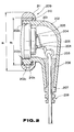
- a headphone unit comprises a housing 202 and an electro-acoustic transducer or speaker unit 201 enclosed in the housing 202.
- the speaker unit 201 includes a magnetic circuit composed of a magnet and a yoke, a coil bobbin driven by the magnetic circuit and a diaphragm attached to the coil bobbin.
- the electrical signals supplied to the coil bobbin are converted into sounds by vibration of the diaphragm, in a well-known manner.
- the housing 202 is of a size such that it can be introduced into the ear's concha.
- the side of the housing 202 corresponding to the sound radiating side of the speaker unit 201 is formed with an opening 202 a .
- the housing 202 is formed of a relatively stiff material having a rubber hardness of about 90 degrees, such as ABS resin.
- the speaker unit 201 is held in position with its peripheral portion fitted in a mating recess 202 b formed in the inner wall of the opening 202 a .
- a connecting cord 203 supplying electric signals to the speaker unit 201 has its terminal portion 204 connected as by soldering to an input terminal 205 of the speaker unit 201.
- the connecting cord exits the housing 202 through a cord extraction opening 206.
- a cylindrical cord bush 207 is provided on a line of extension of the cord extraction opening 206.
- the cord bush 207 is formed of a relatively soft and pliable material and moreover has a plurality of annular grooves 208 as shown, so that it may be flexed easily.
- the portion of the connecting cord 203 exiting out of the cord extraction opening 206 is supported by the cord bush 207 so that it may be flexed smoothly as it is encased in the cord bush 207 when the external force is applied thereto. In this manner, the risk of accidents such as cord breakage otherwise caused by the flexure of the cord in contact with the edge of the cord extraction opening 206, may be minimized.
- the housing 202 is fitted, as shown in Figs. 2 and 3, with a ring member 209 at the perimeter of the opening 202 a .
- the ring member 209 is formed by a base ring 210 and an elastic ring 211 provided at the perimeter of the base ring 210, as shown in Figs. 5 and 6.
- the rings 210, 211 are formed by double-shot moulding from respective different materials.
- the base ring 210 is formed of the same material as the housing 202, and with a toroidal profile with an outside diameter D0 as shown in Figs. 2 and 5.
- the toroidal or ring-shaped peripheral wall of the base ring 210 is formed with a plurality of circumferentially extending slots 210 a , as shown in Fig. 3, to be engaged by mating projections 202 c provided on the outer wall of the housing 202 about the opening 202 a . Between each two neighbouring slots 210 a a rib 210 b is formed.
- the base ring 210 is fitted to the housing 202 in position, with the projections 202 c engaged in the recesses 210 a .
- the elastic ring 211 is formed of a material having a rubber hardness of, for example, 60 degrees, or of a softer material, such as so-called elastomer, having a rubber hardness of 20 to 40 degrees, and is moulded on the outer perimeter of the base ring 210 by double-shot moulding.
- the ring 211 has a prescribed outside diameter D1 as shown in Fig. 2. Portions of the elastic ring 211 cooperating with the base ring 210 are recessed to accommodate the elastic ring 211, while portions of the ring 211 cooperating with the ribs 210 b are formed with tongue-like supporting portions 211 a .
- the elastic ring 211 has its inner peripheral side edge surfaces 211 b , 211 c and the supporting portions 211 a operatively associated with the one and the other peripheral edge surfaces 210 c , 210 d and the ribs 210 b of the base ring 210, as best shown in Fig. 4.
- double-shot moulding is meant a method of moulding including the steps of initially forming a portion of a first material using a first metal mould, placing the portion of the first material in a predetermined position in a second metal mould and injecting and moulding a second material in the second metal mould to form a moulded article composed of the first and the second materials rigidly connected and united to each other.
- a two-colour injection moulding machine is employed, after the portion of the first material is moulded, the predetermined movable portion of the metal mould may be shifted and the second material injected and moulded to form a moulded article formed of two kinds of materials.
- the outside diameter of the elastic ring 211 shown at D1 in Fig. 2 is selected to be larger than the largest likely ear's concha of users, while the outside diameter of the base ring 210 shown at D0 in Fig. 2 is selected to be smaller than the size of the smallest likely ear's concha of the users.
- the elastic ring 211 is formed of a material of low hardness and recessed, it can be easily deformed from the outside diameter in the undeformed state of the elastic ring 211 to an outside diameter approximately equal to the outside diameter of the base ring 210. In this manner, the sealing properties of the housing 202 with respect to the ear's concha when the housing is inserted into the ear's concha are improved, so that satisfactory acoustic properties are obtained in which, as shown at A in Fig. 7, the output in the low frequency range is improved compared to that of the above described previously proposed headphone unit.
- a soft contact feel of the portion of the housing 202 contacting with the ear's concha may also be achieved.
- the base ring 210 and the elastic ring 211 are formed by double-shot moulding so that the materials of the rings 210, 211 are strongly bonded together without the risk of peeling apart even after extended usage.
- electro-acoustic transducer of the invention is not limited to the above described headphone unit, but may also be applied to the earphone or microphone units.
- the rings are provided at the outer side of the opening of the housing exposing the sound input side of the electro-acoustic transducer unit
- the effect of the noises generated by contact of the user's hands or fingers with the housing on the electro-acoustic transducer unit may be minimized.
- the housing since the base ring and the elastic ring are attached to the manually gripped portion of the housing, the housing may be gripped with improved hand feel and slip-proofness.
- a base ring is provided on the outer surface of the perimeter of the opening of the housing, by which the sound radiating side or the sound input side of the electro-acoustic transducer is exposed to the outside, and an elastic ring is provided on the outer periphery of the base ring and is formed of an elastic material by double-shot moulding.
- the elastic ring is subject to considerable deformation and the two materials constituting the elastic ring are united together strongly by the double-shot moulding.
Landscapes
- Physics & Mathematics (AREA)
- Engineering & Computer Science (AREA)
- Acoustics & Sound (AREA)
- Signal Processing (AREA)
- Health & Medical Sciences (AREA)
- Otolaryngology (AREA)
- Headphones And Earphones (AREA)
- Piezo-Electric Transducers For Audible Bands (AREA)
Applications Claiming Priority (5)
| Application Number | Priority Date | Filing Date | Title |
|---|---|---|---|
| JP62275432A JP2671326B2 (ja) | 1987-10-30 | 1987-10-30 | 電気音響変換器 |
| JP275432/87 | 1987-10-30 | ||
| JP62275431A JP2884564B2 (ja) | 1987-10-30 | 1987-10-30 | ヘッドフォン装置 |
| JP275431/87 | 1987-10-30 | ||
| EP88309987A EP0314419B1 (fr) | 1987-10-30 | 1988-10-24 | Transducteur électro-acoustique |
Related Parent Applications (2)
| Application Number | Title | Priority Date | Filing Date |
|---|---|---|---|
| EP88309987A Division EP0314419B1 (fr) | 1987-10-30 | 1988-10-24 | Transducteur électro-acoustique |
| EP88309987.1 Division | 1988-10-24 |
Publications (3)
| Publication Number | Publication Date |
|---|---|
| EP0560415A2 true EP0560415A2 (fr) | 1993-09-15 |
| EP0560415A3 EP0560415A3 (en) | 1993-12-08 |
| EP0560415B1 EP0560415B1 (fr) | 1995-05-17 |
Family
ID=26551469
Family Applications (2)
| Application Number | Title | Priority Date | Filing Date |
|---|---|---|---|
| EP88309987A Expired - Lifetime EP0314419B1 (fr) | 1987-10-30 | 1988-10-24 | Transducteur électro-acoustique |
| EP93109491A Expired - Lifetime EP0560415B1 (fr) | 1987-10-30 | 1988-10-24 | Transducteur électroacoustique |
Family Applications Before (1)
| Application Number | Title | Priority Date | Filing Date |
|---|---|---|---|
| EP88309987A Expired - Lifetime EP0314419B1 (fr) | 1987-10-30 | 1988-10-24 | Transducteur électro-acoustique |
Country Status (6)
| Country | Link |
|---|---|
| US (1) | US4981194A (fr) |
| EP (2) | EP0314419B1 (fr) |
| KR (1) | KR970000394B1 (fr) |
| CA (1) | CA1313253C (fr) |
| DE (2) | DE3852538T2 (fr) |
| MY (1) | MY103630A (fr) |
Cited By (1)
| Publication number | Priority date | Publication date | Assignee | Title |
|---|---|---|---|---|
| WO2007025778A3 (fr) * | 2005-09-02 | 2007-05-03 | Sennheiser Electronic | Oreillette |
Families Citing this family (79)
| Publication number | Priority date | Publication date | Assignee | Title |
|---|---|---|---|---|
| USD288512S (en) * | 1985-04-24 | 1987-03-03 | Thermo-Serv, Inc. | Wine glass |
| USD318865S (en) | 1988-12-13 | 1991-08-06 | Sony Corporation | Earphone |
| JPH03117999A (ja) * | 1989-09-30 | 1991-05-20 | Sony Corp | 電気音響変換器及び音響再生システム |
| US5224171A (en) * | 1990-07-31 | 1993-06-29 | Sony Corporation | Method for printing on synthetic resin molded body and headphone housing on which printing has been made by the method |
| USD353379S (en) | 1992-10-20 | 1994-12-13 | Sony Corporation | Earphone |
| US5359157A (en) * | 1993-08-30 | 1994-10-25 | Jen-Cheng Peng | Contact type indirect conduction, vibrating type microphone |
| AU2951695A (en) * | 1994-07-08 | 1996-02-09 | Plantronics, Inc. | Tri-laterally supported post-auricle communications headset |
| USD371368S (en) | 1994-08-15 | 1996-07-02 | Sony Corporation | Earphone |
| USD391023S (en) | 1996-05-24 | 1998-02-17 | Outils Rubis S.A. | Tweezers |
| USD431553S (en) * | 1999-04-09 | 2000-10-03 | Sony Corporation | Earphone |
| USD430146S (en) * | 1999-06-11 | 2000-08-29 | Chung-Yu Lin | Earphone |
| GB9921142D0 (en) * | 1999-09-08 | 1999-11-10 | Snap On Equipment Ltd | Position-defining and energy-isolating mountings |
| KR200204428Y1 (ko) * | 2000-06-09 | 2000-11-15 | 조경순 | 이어폰 플럭의 홀더링 |
| USD463789S1 (en) | 2001-07-06 | 2002-10-01 | Plantronics, Inc. | Earbud receiver |
| USD485548S1 (en) | 2003-01-28 | 2004-01-20 | Sony Corporation | Earphone |
| USD487077S1 (en) | 2003-01-28 | 2004-02-24 | Sony Corporation | Earphone |
| USD499397S1 (en) | 2004-01-07 | 2004-12-07 | Logitech Europe S.A. | Headset |
| US7349550B2 (en) * | 2004-01-07 | 2008-03-25 | Hearing Components, Inc. | Earbud adapter |
| DE102004010198A1 (de) * | 2004-03-02 | 2005-09-22 | Sennheiser Electronic Gmbh & Co. Kg | Hörer |
| DE102004064142B4 (de) * | 2004-03-02 | 2011-09-15 | Sennheiser Electronic Gmbh & Co. Kg | In-Ear Hörer |
| TWD105539S1 (zh) * | 2004-08-06 | 2005-07-11 | 固昌通訊股份有限公司 | 耳機 |
| TWD105691S1 (zh) * | 2004-08-06 | 2005-07-21 | 固昌通訊股份有限公司 | 耳機 |
| USD519985S1 (en) * | 2005-01-04 | 2006-05-02 | Motorola, Inc. | Earphone pod and similar articles |
| USD533868S1 (en) * | 2005-04-22 | 2006-12-19 | Sony Corporation | Earphone |
| USD533867S1 (en) * | 2005-04-22 | 2006-12-19 | Sony Corporation | Earphone |
| USD531169S1 (en) * | 2005-05-18 | 2006-10-31 | Matsushita Electric Industrial Co., Ltd. | Earphone |
| USD531621S1 (en) * | 2005-08-23 | 2006-11-07 | Cotron Corporation | Earphone |
| USD542782S1 (en) * | 2005-09-12 | 2007-05-15 | Koninklijke Philips Electronics N.V. | Headphone |
| JP4709017B2 (ja) | 2006-01-12 | 2011-06-22 | ソニー株式会社 | イヤホン装置 |
| USD550657S1 (en) * | 2006-03-31 | 2007-09-11 | Creative Technology Ltd | Earphones |
| USD584284S1 (en) * | 2006-05-09 | 2009-01-06 | Bose Corporation | Set of earphones |
| USD582889S1 (en) | 2006-05-09 | 2008-12-16 | Bose Corporation | Earphone |
| USD558735S1 (en) * | 2006-05-09 | 2008-01-01 | Bose Corporation | Headset |
| US8594351B2 (en) | 2006-06-30 | 2013-11-26 | Bose Corporation | Equalized earphones |
| US20080107299A1 (en) * | 2006-11-03 | 2008-05-08 | I-Ming Lin | Earphone |
| US8189845B2 (en) * | 2006-12-21 | 2012-05-29 | Sperian Hearing Protection, Llc | Earbud coupling |
| EP2107898A1 (fr) * | 2007-01-04 | 2009-10-14 | Biosecurity Technologies, Inc. | Dispositif et procédé nouveaux de protection de l'audition et ensemble écouteur bouton sécurisé |
| US20080226114A1 (en) * | 2007-03-15 | 2008-09-18 | Hearing Components, Inc. | Earbud Adapter with Enhanced Frequency Response |
| JP2009055249A (ja) * | 2007-08-24 | 2009-03-12 | Sony Corp | イヤピースおよび電気音響変換装置 |
| US20090232342A1 (en) * | 2008-03-14 | 2009-09-17 | Hearing Components, Inc. | Earbud adapter with increased flexibility region |
| US8891799B2 (en) * | 2008-06-04 | 2014-11-18 | JVC Kenwood Corporation | Earphone |
| CA130063S (en) * | 2008-10-07 | 2009-10-23 | Audio Technica Also Known As Audio Technica Corp Kk | Headphones |
| TW201106719A (en) * | 2009-08-12 | 2011-02-16 | Cotron Corp | Earphone |
| USD622707S1 (en) * | 2009-10-06 | 2010-08-31 | Cheng Uei Precision Industry Co., Ltd. | Earphone |
| USD626117S1 (en) * | 2009-10-30 | 2010-10-26 | Auria Llc | Pair of earphones |
| USD651196S1 (en) * | 2009-12-23 | 2011-12-27 | Sennheiser Electronic Gmbh & Co. Kg | Headphones |
| US20120010735A1 (en) * | 2010-07-09 | 2012-01-12 | Eyal Gilboa | Earpiece attaching system and method |
| JP5418434B2 (ja) * | 2010-07-22 | 2014-02-19 | 株式会社Jvcケンウッド | ヘッドホン |
| JP2012074850A (ja) * | 2010-09-28 | 2012-04-12 | Jvc Kenwood Corp | ヘッドホン |
| US20120328145A1 (en) * | 2010-12-20 | 2012-12-27 | Hon Hai Precision Industry Co., Ltd. | Wired earphone with coiled adhesive tape |
| CN102547504A (zh) * | 2010-12-20 | 2012-07-04 | 鸿富锦精密工业(深圳)有限公司 | 耳机 |
| CN102547503A (zh) * | 2010-12-20 | 2012-07-04 | 鸿富锦精密工业(深圳)有限公司 | 耳机 |
| USD657780S1 (en) * | 2010-12-22 | 2012-04-17 | Sony Mobile Communications Ab | Headset |
| USD674781S1 (en) * | 2011-07-15 | 2013-01-22 | JVC Kenwood Corporation | Earphones |
| US8499886B2 (en) * | 2011-10-14 | 2013-08-06 | Plantronics, Inc. | Expander ear tip |
| USD696230S1 (en) * | 2012-10-30 | 2013-12-24 | Verto Medical Solutions | Earphone |
| USD695723S1 (en) * | 2012-11-20 | 2013-12-17 | Panasonic Corporation | Earphone |
| USD725634S1 (en) * | 2013-10-29 | 2015-03-31 | Harman International Industries, Incorporated | Earphone |
| USD738863S1 (en) | 2014-05-19 | 2015-09-15 | Amazon Technologies, Inc. | Earphones |
| USD746268S1 (en) * | 2014-06-26 | 2015-12-29 | Harman International Industries, Incorporated | Earphone |
| US9578412B2 (en) * | 2014-06-27 | 2017-02-21 | Apple Inc. | Mass loaded earbud with vent chamber |
| US10034112B2 (en) * | 2014-07-25 | 2018-07-24 | Skullcandy, Inc. | Mass port plug for customizing headphone drivers, and related methods |
| JP1529559S (fr) * | 2014-08-27 | 2015-07-27 | ||
| USD762616S1 (en) * | 2014-10-29 | 2016-08-02 | 1More Inc. | Earphone |
| USD762196S1 (en) * | 2015-02-10 | 2016-07-26 | 1More Inc. | Earphone |
| USD778267S1 (en) * | 2015-03-25 | 2017-02-07 | 1More Inc. | Earphone |
| USD773435S1 (en) * | 2015-08-05 | 2016-12-06 | Harman International Industries, Incorporated | Headphone |
| USD784962S1 (en) * | 2015-12-15 | 2017-04-25 | Shenzhen Soundsoul Information Technology Co., Ltd. | Pair of earphones |
| USD786217S1 (en) * | 2016-02-19 | 2017-05-09 | Adrian Stoch | Combined necklace and earphone |
| USD786221S1 (en) * | 2016-02-19 | 2017-05-09 | Adrian Stoch | Earbud |
| USD796486S1 (en) * | 2016-03-13 | 2017-09-05 | Huiyang District Yonghu Town Xingcheng Electronic Processing Plant | Wireless headset |
| USD869445S1 (en) * | 2019-05-22 | 2019-12-10 | Shenzhen Qianhai Patuoxun Network And Technology Co., Ltd | Earphone |
| USD890724S1 (en) * | 2019-11-22 | 2020-07-21 | Stb International Limited | Earphone |
| USD883260S1 (en) * | 2019-12-25 | 2020-05-05 | Shenzhen Qianhai Patuoxun Network And Technology Co., Ltd | Earphone |
| USD893462S1 (en) * | 2020-03-05 | 2020-08-18 | Shenzhen Humboldt Technology Co., Ltd | Headphone |
| USD1038084S1 (en) * | 2021-08-19 | 2024-08-06 | Harman International Industries, Incorporated | Headphone |
| US11638081B2 (en) * | 2021-09-04 | 2023-04-25 | Bose Corporation | Earphone port |
| US12137312B2 (en) | 2022-02-22 | 2024-11-05 | Apple Inc. | Portable wireless listening device |
| CA223977S (en) * | 2023-03-07 | 2025-06-27 | Strongbyte Solutions Ltd | Earpiece |
Family Cites Families (8)
| Publication number | Priority date | Publication date | Assignee | Title |
|---|---|---|---|---|
| US3671685A (en) * | 1969-01-25 | 1972-06-20 | Instrument Systems Corp | Electro-acoustic headset with ratchet |
| US3787899A (en) * | 1972-07-11 | 1974-01-29 | Imp Optical Co Ltd | Ear muff assembly |
| AT323823B (de) * | 1973-06-19 | 1975-07-25 | Akg Akustische Kino Geraete | Schallsender nach dem zweinegsystem, insbesondere für kopphörer |
| JPS574880U (fr) * | 1980-06-06 | 1982-01-11 | ||
| GB2082020B (en) * | 1980-06-30 | 1985-05-30 | Pioneer Electronic Corp | Ear speaker |
| JPH0659120B2 (ja) * | 1983-05-31 | 1994-08-03 | ソニー株式会社 | ヘツドホン |
| JPS6223299A (ja) * | 1985-07-23 | 1987-01-31 | Sony Corp | 電気音響変換器 |
| JPH0450718Y2 (fr) * | 1986-02-28 | 1992-11-30 |
-
1988
- 1988-10-18 US US07/259,513 patent/US4981194A/en not_active Expired - Lifetime
- 1988-10-19 CA CA000580599A patent/CA1313253C/fr not_active Expired - Lifetime
- 1988-10-24 EP EP88309987A patent/EP0314419B1/fr not_active Expired - Lifetime
- 1988-10-24 DE DE3852538T patent/DE3852538T2/de not_active Expired - Lifetime
- 1988-10-24 EP EP93109491A patent/EP0560415B1/fr not_active Expired - Lifetime
- 1988-10-24 DE DE3853837T patent/DE3853837T2/de not_active Expired - Lifetime
- 1988-10-26 MY MYPI88001217A patent/MY103630A/en unknown
- 1988-10-28 KR KR1019880014073A patent/KR970000394B1/ko not_active Expired - Lifetime
Cited By (1)
| Publication number | Priority date | Publication date | Assignee | Title |
|---|---|---|---|---|
| WO2007025778A3 (fr) * | 2005-09-02 | 2007-05-03 | Sennheiser Electronic | Oreillette |
Also Published As
| Publication number | Publication date |
|---|---|
| DE3852538T2 (de) | 1995-05-04 |
| EP0314419A2 (fr) | 1989-05-03 |
| DE3852538D1 (de) | 1995-02-02 |
| HK1006908A1 (en) | 1999-03-19 |
| EP0560415A3 (en) | 1993-12-08 |
| HK1006910A1 (en) | 1999-03-19 |
| EP0314419A3 (fr) | 1991-01-09 |
| DE3853837T2 (de) | 1995-09-28 |
| EP0314419B1 (fr) | 1994-12-21 |
| MY103630A (en) | 1993-08-28 |
| KR890007602A (ko) | 1989-06-20 |
| KR970000394B1 (ko) | 1997-01-09 |
| DE3853837D1 (de) | 1995-06-22 |
| EP0560415B1 (fr) | 1995-05-17 |
| CA1313253C (fr) | 1993-01-26 |
| US4981194A (en) | 1991-01-01 |
Similar Documents
| Publication | Publication Date | Title |
|---|---|---|
| EP0560415B1 (fr) | Transducteur électroacoustique | |
| US5142587A (en) | Intra-concha type electroacoustic transducer for use with audio devices etc. | |
| EP0373816B1 (fr) | Appareil transducteur électro-acoustique | |
| US8270648B2 (en) | Earpiece and electro-acoustic transducer | |
| US5420935A (en) | Auricle insertion headphone with improved grill | |
| KR860001263B1 (ko) | 전기음향 변환기 | |
| US20120243726A1 (en) | Earphone | |
| CN112788460B (zh) | 耳机、耳机的驱动部用罩以及罩套装 | |
| US20030081794A1 (en) | Insert earphone | |
| GB2220819A (en) | Electroacoustic transducer | |
| GB1334183A (en) | Headset | |
| GB2458225A (en) | Earbud adapter with increased flexibility region | |
| KR20000058143A (ko) | 입체 음향 이어폰 장치, 이어폰 및 이어폰 삽입 방법 | |
| WO2011007448A1 (fr) | Ecouteur et dispositif électronique | |
| KR102545214B1 (ko) | 이어폰용 이어팁 및 이를 구비하는 이어폰 | |
| JPH07154888A (ja) | 電気音響変換装置 | |
| JP2884564B2 (ja) | ヘッドフォン装置 | |
| HK1006908B (en) | Electro-acoustic transducer | |
| HK1006910B (en) | Electro-acoustic transducer | |
| JP2671326B2 (ja) | 電気音響変換器 | |
| WO2002084982A9 (fr) | Ecouteur pour radio/telephone | |
| JPS644398B2 (fr) | ||
| JPS6379500A (ja) | 電気音響変換器 | |
| JP2021175144A (ja) | 軟骨伝導イヤホン及び聴取機器 | |
| CN118104251B (zh) | 开放式耳机 |
Legal Events
| Date | Code | Title | Description |
|---|---|---|---|
| PUAI | Public reference made under article 153(3) epc to a published international application that has entered the european phase |
Free format text: ORIGINAL CODE: 0009012 |
|
| 17P | Request for examination filed |
Effective date: 19930626 |
|
| AC | Divisional application: reference to earlier application |
Ref document number: 314419 Country of ref document: EP |
|
| AK | Designated contracting states |
Kind code of ref document: A2 Designated state(s): DE FR GB NL |
|
| PUAL | Search report despatched |
Free format text: ORIGINAL CODE: 0009013 |
|
| AK | Designated contracting states |
Kind code of ref document: A3 Designated state(s): DE FR GB NL |
|
| 17Q | First examination report despatched |
Effective date: 19940721 |
|
| GRAA | (expected) grant |
Free format text: ORIGINAL CODE: 0009210 |
|
| AC | Divisional application: reference to earlier application |
Ref document number: 314419 Country of ref document: EP |
|
| AK | Designated contracting states |
Kind code of ref document: B1 Designated state(s): DE FR GB NL |
|
| REF | Corresponds to: |
Ref document number: 3853837 Country of ref document: DE Date of ref document: 19950622 |
|
| ET | Fr: translation filed | ||
| PLBE | No opposition filed within time limit |
Free format text: ORIGINAL CODE: 0009261 |
|
| STAA | Information on the status of an ep patent application or granted ep patent |
Free format text: STATUS: NO OPPOSITION FILED WITHIN TIME LIMIT |
|
| 26N | No opposition filed | ||
| REG | Reference to a national code |
Ref country code: GB Ref legal event code: IF02 |
|
| PGFP | Annual fee paid to national office [announced via postgrant information from national office to epo] |
Ref country code: NL Payment date: 20071003 Year of fee payment: 20 Ref country code: DE Payment date: 20071018 Year of fee payment: 20 |
|
| PGFP | Annual fee paid to national office [announced via postgrant information from national office to epo] |
Ref country code: GB Payment date: 20071024 Year of fee payment: 20 Ref country code: FR Payment date: 20071009 Year of fee payment: 20 |
|
| REG | Reference to a national code |
Ref country code: GB Ref legal event code: PE20 Expiry date: 20081023 |
|
| PG25 | Lapsed in a contracting state [announced via postgrant information from national office to epo] |
Ref country code: NL Free format text: LAPSE BECAUSE OF EXPIRATION OF PROTECTION Effective date: 20081024 |
|
| NLV7 | Nl: ceased due to reaching the maximum lifetime of a patent |
Effective date: 20081024 |
|
| PG25 | Lapsed in a contracting state [announced via postgrant information from national office to epo] |
Ref country code: GB Free format text: LAPSE BECAUSE OF EXPIRATION OF PROTECTION Effective date: 20081023 |