EP0560419A2 - Verfahren zur Herstellung eines Gaszuführsystems für einen Gasbrenner und daraus erhaltenes Produkt - Google Patents
Verfahren zur Herstellung eines Gaszuführsystems für einen Gasbrenner und daraus erhaltenes Produkt Download PDFInfo
- Publication number
- EP0560419A2 EP0560419A2 EP93200513A EP93200513A EP0560419A2 EP 0560419 A2 EP0560419 A2 EP 0560419A2 EP 93200513 A EP93200513 A EP 93200513A EP 93200513 A EP93200513 A EP 93200513A EP 0560419 A2 EP0560419 A2 EP 0560419A2
- Authority
- EP
- European Patent Office
- Prior art keywords
- nozzle
- conduit
- seat
- gas
- side wall
- Prior art date
- Legal status (The legal status is an assumption and is not a legal conclusion. Google has not performed a legal analysis and makes no representation as to the accuracy of the status listed.)
- Granted
Links
Images
Classifications
-
- B—PERFORMING OPERATIONS; TRANSPORTING
- B21—MECHANICAL METAL-WORKING WITHOUT ESSENTIALLY REMOVING MATERIAL; PUNCHING METAL
- B21K—MAKING FORGED OR PRESSED METAL PRODUCTS, e.g. HORSE-SHOES, RIVETS, BOLTS OR WHEELS
- B21K25/00—Uniting components to form integral members, e.g. turbine wheels and shafts, caulks with inserts, with or without shaping of the components
-
- F—MECHANICAL ENGINEERING; LIGHTING; HEATING; WEAPONS; BLASTING
- F16—ENGINEERING ELEMENTS AND UNITS; GENERAL MEASURES FOR PRODUCING AND MAINTAINING EFFECTIVE FUNCTIONING OF MACHINES OR INSTALLATIONS; THERMAL INSULATION IN GENERAL
- F16B—DEVICES FOR FASTENING OR SECURING CONSTRUCTIONAL ELEMENTS OR MACHINE PARTS TOGETHER, e.g. NAILS, BOLTS, CIRCLIPS, CLAMPS, CLIPS OR WEDGES; JOINTS OR JOINTING
- F16B17/00—Connecting constructional elements or machine parts by a part of or on one member entering a hole in the other and involving plastic deformation
-
- F—MECHANICAL ENGINEERING; LIGHTING; HEATING; WEAPONS; BLASTING
- F23—COMBUSTION APPARATUS; COMBUSTION PROCESSES
- F23D—BURNERS
- F23D14/00—Burners for combustion of a gas, e.g. of a gas stored under pressure as a liquid
- F23D14/46—Details
Definitions
- This invention relates to gas burners, particularly to a method of manufacturing a gas feeder for a gas burner and a gas feeder manufactured by the method, as well as to a nozzle for use with said gas feeder.
- Burner nozzles have been conventionally provided as machine metal pieces which are turned from an axially bored hexagonal bar stock, usually made of brass. These are threaded to screw fit into matingly threaded holes in a gas delivery conduit.
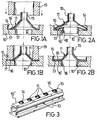
- FIG. 1A and 1B Shown at 10 in Figures 1A and 1B is the wall of a gas conduit, such as a pipe header similar to that depicted in Figure 3, and at 11 a nozzle stamped from sheet metal.
- the conduit 10 has a circular opening 12 which widens out stepwise toward the conduit exterior so as to provide a depressed region adapted to form a seat for the nozzle.
- This seat comprises a base 13 having an annular surface and a side wall 14 having a substantially cylindrical surface.
- the nozzle 11 has a basically funnel-like shape with an outlet conduit 15 which forms the nozzle bore and with a peripheral portion arranged to bear on the seat base 13.
- Figure 1A shows the two portions during the manufacturing step which precedes the securing step; it can be seen that the end diameter of the nozzle peripheral portion 16 is slightly smaller than the large diameter of the base 13 annulus.
- the conical portion of the funnel shape adjoining the outlet conduit 15 has preferably a taper angle of 60°, and its conical periphery 16 has a taper angle of 120° or more.
- the step of securing the nozzle 11 on the conduit 10 involves application of a compressive force to the nozzle 11 to thereby expand its peripheral or edge region 16 by deformation until said region engages, by the free end 17 thereof, the cylindrical side wall 14 that bounds the nozzle seat.
- This compressive force is preferably applied using a tubular cylinder tool, shown at 19, which can be moved along a coaxial direction with the nozzle and has a working surface substantially to match the base 13 annulus.
- the sheet metal whence the nozzle 11 is formed would be a harder material, such as brass or stainless steel, than that forming the conduit 10, which may be made of alluminium, and the outer edge 17 of the nozzle is sharp-ended in the example illustrated by Figures 1A and 1B, whereby the nozzle 11 under compression will cut with its edge 17 into the seat side wall 14, and on release of the compressive force, be held securely to the conduit, as shown in Figure 1B, by the undercut brought about by the cutting action.
- This securement form is effective to provide a good mechanical gas-tight fit.
- the nozzle 11 differs from that shown in Figures 1A and 1B by that its edge region 16 has a portion 16' bent inwardly of the nozzle and a cylindrical portion 18 merging with the bent portion 16'.
- This cylindrical portion 18 has an outer section substantially similar to that of the narrow portion of the opening 12 and can foster the nozzle centering within the opening as well as an increase of the contact surface area between the nozzle and the opening for improved tightness of the fit.
- a circumferential groove may be conveniently formed in the cylindrical side wall 14 at the connecting edge to the base 13. This groove should have a width appropriate to allow the circumferential corner edge of the nozzle edge region 16 to penetrate it after the compressive action.
- an effective mechanical anchor and excellent tight fit can be also provided.
- the gas feeder consisting of the gas supply conduit 10 and some nozzles 11 mounted thereon, is shown in perspective in Figure 3. It is a pipe header for a gas burner, no further shown, and has a flat portion 10' formed with longitudinally aligned holes each to accomodate a nozzle like that shown in Figures 1A and 1B or Figures 2A and 2B.
- the gas feeder of this invention is simple and economical to manufacture because the nozzles can be produced in large volumes by a progressive stamping procedure, that is without any machining, and the assembly can be made by just exerting a push force on the nozzles as may effectively and quickly be done on automated equipment.
- the gas feeder also provides a highly reliable tight fit between the nozzle and the conduit by virtue of the securement form described above.
Landscapes
- Engineering & Computer Science (AREA)
- General Engineering & Computer Science (AREA)
- Mechanical Engineering (AREA)
- Chemical & Material Sciences (AREA)
- Combustion & Propulsion (AREA)
- Gas Burners (AREA)
Applications Claiming Priority (2)
| Application Number | Priority Date | Filing Date | Title |
|---|---|---|---|
| ITMI920561A IT1254255B (it) | 1992-03-11 | 1992-03-11 | Procedimento per la fabbricazione di un erogatore per bruciatore di gas e prodotto ottenuto con tale procedimento |
| ITMI920561 | 1992-03-11 |
Publications (3)
| Publication Number | Publication Date |
|---|---|
| EP0560419A2 true EP0560419A2 (de) | 1993-09-15 |
| EP0560419A3 EP0560419A3 (de) | 1993-10-27 |
| EP0560419B1 EP0560419B1 (de) | 1996-12-27 |
Family
ID=11362375
Family Applications (1)
| Application Number | Title | Priority Date | Filing Date |
|---|---|---|---|
| EP93200513A Expired - Lifetime EP0560419B1 (de) | 1992-03-11 | 1993-02-24 | Verfahren zur Herstellung eines Gaszuführsystems für einen Gasbrenner und daraus erhaltenes Produkt |
Country Status (3)
| Country | Link |
|---|---|
| EP (1) | EP0560419B1 (de) |
| DE (1) | DE69306834T2 (de) |
| IT (1) | IT1254255B (de) |
Cited By (17)
| Publication number | Priority date | Publication date | Assignee | Title |
|---|---|---|---|---|
| FR2722867A1 (fr) * | 1994-07-25 | 1996-01-26 | Sdecc | Support de bruleur a rampe d'injection integree |
| US5950573A (en) * | 1998-10-16 | 1999-09-14 | Srp 687 Pty. Ltd. | Power vented water heater with air inlet |
| US6003477A (en) * | 1995-04-04 | 1999-12-21 | Srp 687 Pty. Ltd. | Ignition inhibiting gas water heater |
| WO2000004308A1 (de) * | 1998-07-17 | 2000-01-27 | Robert Bosch Gmbh | Scheibe, insbesondere dichtungsscheibe |
| US6082310A (en) * | 1995-04-04 | 2000-07-04 | Srp 687 Pty. Ltd. | Air inlets for water heaters |
| US6085700A (en) * | 1998-08-21 | 2000-07-11 | Srp 687 Pty Ltd. | Heat sensitive air inlets for water heaters |
| US6116195A (en) * | 1998-10-20 | 2000-09-12 | Srp 687 Pty Ltd. | Flame traps for water heaters |
| US6135061A (en) * | 1995-04-04 | 2000-10-24 | Srp 687 Pty Ltd. | Air inlets for water heaters |
| US6138613A (en) * | 1995-04-04 | 2000-10-31 | Srp 687 Pty Ltd. | Ignition inhibiting gas water heater |
| US6142106A (en) * | 1998-08-21 | 2000-11-07 | Srp 687 Pty Ltd. | Air inlets for combustion chamber of water heater |
| US6155211A (en) * | 1995-04-04 | 2000-12-05 | Srp 687 Pty Ltd. | Air inlets for water heaters |
| US6196164B1 (en) | 1995-04-04 | 2001-03-06 | Srp 687 Pty. Ltd. | Ignition inhibiting gas water heater |
| US6200131B1 (en) * | 2000-02-29 | 2001-03-13 | Recot, Inc. | Quick-connect burner set for ovens |
| AT407564B (de) * | 1998-05-20 | 2001-04-25 | Vaillant Gmbh | Gasbrenner |
| US6269779B2 (en) | 1998-08-21 | 2001-08-07 | Srp 687 Pty Ltd. | Sealed access assembly for water heaters |
| US6295951B1 (en) | 1995-04-04 | 2001-10-02 | Srp 687 Pty. Ltd. | Ignition inhibiting gas water heater |
| US6302062B2 (en) | 1998-08-21 | 2001-10-16 | Srp 687 Pty Ltd. | Sealed access assembly for water heaters |
Family Cites Families (2)
| Publication number | Priority date | Publication date | Assignee | Title |
|---|---|---|---|---|
| US3198874A (en) * | 1961-01-23 | 1965-08-03 | Standard Pressed Steel Co | Semi-conductor housings and method of making the same |
| US3768962A (en) * | 1972-10-02 | 1973-10-30 | F Baranowski | Gas torch |
-
1992
- 1992-03-11 IT ITMI920561A patent/IT1254255B/it active
-
1993
- 1993-02-24 EP EP93200513A patent/EP0560419B1/de not_active Expired - Lifetime
- 1993-02-24 DE DE69306834T patent/DE69306834T2/de not_active Expired - Fee Related
Cited By (23)
| Publication number | Priority date | Publication date | Assignee | Title |
|---|---|---|---|---|
| FR2722867A1 (fr) * | 1994-07-25 | 1996-01-26 | Sdecc | Support de bruleur a rampe d'injection integree |
| EP0694732A1 (de) * | 1994-07-25 | 1996-01-31 | SAUNIER DUVAL EAU CHAUDE CHAUFFAGE S.D.E.C.C. - Société anonyme | Brennerhalterung mit integrierter Einspritzleitung |
| US6138613A (en) * | 1995-04-04 | 2000-10-31 | Srp 687 Pty Ltd. | Ignition inhibiting gas water heater |
| US6418883B2 (en) | 1995-04-04 | 2002-07-16 | Srp 687 Pty. Ltd. | Ignition inhibiting gas water heater |
| US6082310A (en) * | 1995-04-04 | 2000-07-04 | Srp 687 Pty. Ltd. | Air inlets for water heaters |
| US6085699A (en) * | 1995-04-04 | 2000-07-11 | Srp 687 Pty Ltd. | Air inlets for water heaters |
| US6295951B1 (en) | 1995-04-04 | 2001-10-02 | Srp 687 Pty. Ltd. | Ignition inhibiting gas water heater |
| US6003477A (en) * | 1995-04-04 | 1999-12-21 | Srp 687 Pty. Ltd. | Ignition inhibiting gas water heater |
| US6135061A (en) * | 1995-04-04 | 2000-10-24 | Srp 687 Pty Ltd. | Air inlets for water heaters |
| US6401668B2 (en) | 1995-04-04 | 2002-06-11 | Srp 687 Pty. Ltd. | Ignition inhibiting gas water heater |
| US6155211A (en) * | 1995-04-04 | 2000-12-05 | Srp 687 Pty Ltd. | Air inlets for water heaters |
| US6196164B1 (en) | 1995-04-04 | 2001-03-06 | Srp 687 Pty. Ltd. | Ignition inhibiting gas water heater |
| AT407564B (de) * | 1998-05-20 | 2001-04-25 | Vaillant Gmbh | Gasbrenner |
| WO2000004308A1 (de) * | 1998-07-17 | 2000-01-27 | Robert Bosch Gmbh | Scheibe, insbesondere dichtungsscheibe |
| US6085700A (en) * | 1998-08-21 | 2000-07-11 | Srp 687 Pty Ltd. | Heat sensitive air inlets for water heaters |
| US6142106A (en) * | 1998-08-21 | 2000-11-07 | Srp 687 Pty Ltd. | Air inlets for combustion chamber of water heater |
| US6223697B1 (en) | 1998-08-21 | 2001-05-01 | Srp 687 Pty Ltd. | Water heater with heat sensitive air inlet |
| US6269779B2 (en) | 1998-08-21 | 2001-08-07 | Srp 687 Pty Ltd. | Sealed access assembly for water heaters |
| US6302062B2 (en) | 1998-08-21 | 2001-10-16 | Srp 687 Pty Ltd. | Sealed access assembly for water heaters |
| US5950573A (en) * | 1998-10-16 | 1999-09-14 | Srp 687 Pty. Ltd. | Power vented water heater with air inlet |
| US6116195A (en) * | 1998-10-20 | 2000-09-12 | Srp 687 Pty Ltd. | Flame traps for water heaters |
| US6293230B1 (en) | 1998-10-20 | 2001-09-25 | Srp 687 Pty Ltd. | Water heaters with flame traps |
| US6200131B1 (en) * | 2000-02-29 | 2001-03-13 | Recot, Inc. | Quick-connect burner set for ovens |
Also Published As
| Publication number | Publication date |
|---|---|
| DE69306834T2 (de) | 1997-05-07 |
| IT1254255B (it) | 1995-09-14 |
| ITMI920561A0 (it) | 1992-03-11 |
| DE69306834D1 (de) | 1997-02-06 |
| EP0560419B1 (de) | 1996-12-27 |
| EP0560419A3 (de) | 1993-10-27 |
| ITMI920561A1 (it) | 1993-09-11 |
Similar Documents
| Publication | Publication Date | Title |
|---|---|---|
| EP0560419B1 (de) | Verfahren zur Herstellung eines Gaszuführsystems für einen Gasbrenner und daraus erhaltenes Produkt | |
| US6491487B1 (en) | Double-ended self-attaching stud | |
| US4459073A (en) | Fasteners with piercing and riveting performance | |
| US6592311B2 (en) | Double-ended self-attaching stud | |
| US3810291A (en) | Installation die and nut and method of installing a nut in a panel | |
| KR100732306B1 (ko) | 블라인드 패스너 | |
| HU9403706D0 (en) | Method of making connection element designed to be secure against rotation and insert ejection by pressing pressure element in a plate and pressure element according to this method | |
| KR20070047799A (ko) | 푸쉬형 리벳리스 너트 플레이트 및 이를 설치하는 방법 및장치 | |
| JPH0829392B2 (ja) | ピアスナットの製造装置 | |
| JPH03210931A (ja) | 自己ピアシング・リベッティング・ファスナのパネルへの取付け法及び自己ピアシング・リベッティング・ファスナのパネルへの取付け用ダイ部材 | |
| JP2000266031A (ja) | ボルトとスリーブのアセンブリ | |
| US4335753A (en) | Hose connectors and hoses equipped with same | |
| EP0278433A1 (de) | Befestigungsanordnung | |
| US6081984A (en) | Method of fastening members of an assembly | |
| US5733086A (en) | Combined rivet/nail components and methods for using same | |
| US6994486B1 (en) | Functional element and panel assembly | |
| US6679664B2 (en) | Plate nut assembly | |
| US6484385B2 (en) | Method for manufacturing self-sealing reinforcement tie rods for HVAC ducts | |
| US5472303A (en) | Blind rivet-type clamping fastener | |
| US20070253770A1 (en) | Joined connection, joining element and method for inserting a joining element into a component | |
| JP2001105046A (ja) | パンチ機構のストリッパ落下防止装置 | |
| JP4790904B2 (ja) | 閉端型ブラインドリベット | |
| JPS57137031A (en) | Jointing method of flange to steel pipe | |
| EP0250694A2 (de) | Verfahren und Vorrichtung zum Endformen von Verbindungsrohren | |
| JP2507849B2 (ja) | 座金付ナットとその製造方法 |
Legal Events
| Date | Code | Title | Description |
|---|---|---|---|
| PUAI | Public reference made under article 153(3) epc to a published international application that has entered the european phase |
Free format text: ORIGINAL CODE: 0009012 |
|
| PUAL | Search report despatched |
Free format text: ORIGINAL CODE: 0009013 |
|
| AK | Designated contracting states |
Kind code of ref document: A2 Designated state(s): DE ES FR GB |
|
| AK | Designated contracting states |
Kind code of ref document: A3 Designated state(s): DE ES FR GB |
|
| 17P | Request for examination filed |
Effective date: 19940415 |
|
| 17Q | First examination report despatched |
Effective date: 19950518 |
|
| GRAG | Despatch of communication of intention to grant |
Free format text: ORIGINAL CODE: EPIDOS AGRA |
|
| GRAH | Despatch of communication of intention to grant a patent |
Free format text: ORIGINAL CODE: EPIDOS IGRA |
|
| GRAH | Despatch of communication of intention to grant a patent |
Free format text: ORIGINAL CODE: EPIDOS IGRA |
|
| GRAA | (expected) grant |
Free format text: ORIGINAL CODE: 0009210 |
|
| AK | Designated contracting states |
Kind code of ref document: B1 Designated state(s): DE ES FR GB |
|
| PG25 | Lapsed in a contracting state [announced via postgrant information from national office to epo] |
Ref country code: ES Free format text: THE PATENT HAS BEEN ANNULLED BY A DECISION OF A NATIONAL AUTHORITY Effective date: 19961227 |
|
| ET | Fr: translation filed | ||
| REF | Corresponds to: |
Ref document number: 69306834 Country of ref document: DE Date of ref document: 19970206 |
|
| PLBE | No opposition filed within time limit |
Free format text: ORIGINAL CODE: 0009261 |
|
| STAA | Information on the status of an ep patent application or granted ep patent |
Free format text: STATUS: NO OPPOSITION FILED WITHIN TIME LIMIT |
|
| 26N | No opposition filed | ||
| REG | Reference to a national code |
Ref country code: GB Ref legal event code: IF02 |
|
| PGFP | Annual fee paid to national office [announced via postgrant information from national office to epo] |
Ref country code: GB Payment date: 20020220 Year of fee payment: 10 |
|
| PG25 | Lapsed in a contracting state [announced via postgrant information from national office to epo] |
Ref country code: GB Free format text: LAPSE BECAUSE OF NON-PAYMENT OF DUE FEES Effective date: 20030224 |
|
| GBPC | Gb: european patent ceased through non-payment of renewal fee | ||
| PGFP | Annual fee paid to national office [announced via postgrant information from national office to epo] |
Ref country code: DE Payment date: 20060117 Year of fee payment: 14 |
|
| PGFP | Annual fee paid to national office [announced via postgrant information from national office to epo] |
Ref country code: FR Payment date: 20060228 Year of fee payment: 14 |
|
| REG | Reference to a national code |
Ref country code: FR Ref legal event code: ST Effective date: 20071030 |
|
| PG25 | Lapsed in a contracting state [announced via postgrant information from national office to epo] |
Ref country code: DE Free format text: LAPSE BECAUSE OF NON-PAYMENT OF DUE FEES Effective date: 20070901 |
|
| PG25 | Lapsed in a contracting state [announced via postgrant information from national office to epo] |
Ref country code: FR Free format text: LAPSE BECAUSE OF NON-PAYMENT OF DUE FEES Effective date: 20070228 |