EP0560650A1 - Element eines elektrischen Verbinders - Google Patents
Element eines elektrischen Verbinders Download PDFInfo
- Publication number
- EP0560650A1 EP0560650A1 EP93400556A EP93400556A EP0560650A1 EP 0560650 A1 EP0560650 A1 EP 0560650A1 EP 93400556 A EP93400556 A EP 93400556A EP 93400556 A EP93400556 A EP 93400556A EP 0560650 A1 EP0560650 A1 EP 0560650A1
- Authority
- EP
- European Patent Office
- Prior art keywords
- connector element
- closure plug
- element according
- cartridge
- electrical
- Prior art date
- Legal status (The legal status is an assumption and is not a legal conclusion. Google has not performed a legal analysis and makes no representation as to the accuracy of the status listed.)
- Granted
Links
- 229910052751 metal Inorganic materials 0.000 claims abstract description 22
- 239000002184 metal Substances 0.000 claims abstract description 21
- 239000003990 capacitor Substances 0.000 claims description 9
- 238000010292 electrical insulation Methods 0.000 claims description 6
- 239000011810 insulating material Substances 0.000 claims description 4
- 230000005540 biological transmission Effects 0.000 description 5
- 238000005192 partition Methods 0.000 description 4
- 238000002955 isolation Methods 0.000 description 2
- 208000031968 Cadaver Diseases 0.000 description 1
- 235000012571 Ficus glomerata Nutrition 0.000 description 1
- 240000000365 Ficus racemosa Species 0.000 description 1
- 239000004606 Fillers/Extenders Substances 0.000 description 1
- 235000015125 Sterculia urens Nutrition 0.000 description 1
- 230000000295 complement effect Effects 0.000 description 1
- 239000004020 conductor Substances 0.000 description 1
- 238000002788 crimping Methods 0.000 description 1
- 239000012777 electrically insulating material Substances 0.000 description 1
- 238000009422 external insulation Methods 0.000 description 1
- 230000002093 peripheral effect Effects 0.000 description 1
- 238000007789 sealing Methods 0.000 description 1
Images


Classifications
-
- H—ELECTRICITY
- H01—ELECTRIC ELEMENTS
- H01R—ELECTRICALLY-CONDUCTIVE CONNECTIONS; STRUCTURAL ASSOCIATIONS OF A PLURALITY OF MUTUALLY-INSULATED ELECTRICAL CONNECTING ELEMENTS; COUPLING DEVICES; CURRENT COLLECTORS
- H01R13/00—Details of coupling devices of the kinds covered by groups H01R12/70 or H01R24/00 - H01R33/00
- H01R13/66—Structural association with built-in electrical component
- H01R13/6608—Structural association with built-in electrical component with built-in single component
- H01R13/6625—Structural association with built-in electrical component with built-in single component with capacitive component
-
- H—ELECTRICITY
- H01—ELECTRIC ELEMENTS
- H01R—ELECTRICALLY-CONDUCTIVE CONNECTIONS; STRUCTURAL ASSOCIATIONS OF A PLURALITY OF MUTUALLY-INSULATED ELECTRICAL CONNECTING ELEMENTS; COUPLING DEVICES; CURRENT COLLECTORS
- H01R24/00—Two-part coupling devices, or either of their cooperating parts, characterised by their overall structure
- H01R24/38—Two-part coupling devices, or either of their cooperating parts, characterised by their overall structure having concentrically or coaxially arranged contacts
- H01R24/40—Two-part coupling devices, or either of their cooperating parts, characterised by their overall structure having concentrically or coaxially arranged contacts specially adapted for high frequency
- H01R24/54—Intermediate parts, e.g. adapters, splitters or elbows
- H01R24/547—Splitters
-
- H—ELECTRICITY
- H01—ELECTRIC ELEMENTS
- H01R—ELECTRICALLY-CONDUCTIVE CONNECTIONS; STRUCTURAL ASSOCIATIONS OF A PLURALITY OF MUTUALLY-INSULATED ELECTRICAL CONNECTING ELEMENTS; COUPLING DEVICES; CURRENT COLLECTORS
- H01R2103/00—Two poles
-
- H—ELECTRICITY
- H01—ELECTRIC ELEMENTS
- H01R—ELECTRICALLY-CONDUCTIVE CONNECTIONS; STRUCTURAL ASSOCIATIONS OF A PLURALITY OF MUTUALLY-INSULATED ELECTRICAL CONNECTING ELEMENTS; COUPLING DEVICES; CURRENT COLLECTORS
- H01R2201/00—Connectors or connections adapted for particular applications
- H01R2201/16—Connectors or connections adapted for particular applications for telephony
Definitions
- the present invention relates to an electrical connector element of the type comprising a metal body and the rear wiring face of which must be connected to at least one electrical cable and to at least one electrical component.
- Such a type of electrical connector element is used in particular in data transmission networks in which two complementary connector elements are used, such as a plug and a socket of the circuit loop type.
- This type of connector also called “self-looping” is used when it is desired, for example, to connect a device in series in an existing circuit without interrupting the circuit for a period greater than an authorized breaking time.
- the base which is interposed in the circuit comprises one or more pairs of electrical contact elements, the two contact elements of which are electrically connected together by a device. connection comprising a switch, the opening of which is caused when the base is coupled to an additional plug connected to the device to be connected in series.
- the various plugs are connected to the earth with the interposition of the capacity, with the exception of that located substantially in the middle of the BUS line which is connected directly to the earth .
- the present invention provides an electrical connector element of the type comprising a metal body and the rear wiring face of which is connected to at least one electrical cable and to at least one electrical component, characterized in that it comprises a hollow plug for closing the rear end of the metal body of the connector element which delimits an interior chamber in which a cartridge carrying the electrical component is arranged and the side skirt of which has at least one lateral opening for the passage of the electrical cable .
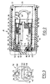
- FIG. 1 recognizes an electrical connector element 10 of which only the metallic body 12 has been shown.
- the cylindrical metallic body 12 of cylindrical shape is designed to receive a block of insulating material which receives electrical contact elements.
- the electrical connector element 10 may for example belong to a connection assembly of the circuit looping type such as that described and represented in French patent application No. 91 13502.
- the electrical contact elements are intended to be connected, by the rear wiring face 14 of the electrical connector element 10 to electrical wires of an electrical cable, not shown.
- the metal body 12 has, near its rear end, an external thread 16 onto which is screwed a nut 18 for mounting a closure plug 20 of the rear wiring face 14 of the connector element 10.
- the mounting nut 18 is mounted to rotate freely on the free front edge 22 of the closure plug 20 by radial crimping of a folded edge 24 which cooperates with a radial groove 26 formed on the outer peripheral surface of the front edge 22 of the plug closing 20.
- the front edge 22 of the plug 20 has axial teeth 28 which cooperate with corresponding axial teeth 30 formed at the rear end of the body 12 to immobilize the closure plug 20 in rotation relative to the body 12 and this in a determined angular position. .
- the mounting nut 18 is coated with a cap of insulating material 19.
- the closure plug 20 is a metallic element of generally cylindrical shape comprising a lateral skirt 32 and a rear transverse bottom 34.
- Ground continuity between the metal body 12 of the connector element 10 and the closure plug 20 is ensured by the metal mounting nut 18 and by the teeth 28 and 30 held in contact and by the tightening of the nut .
- the hollow closure cap 20 defines an interior chamber 36.
- the lateral skirt 32 In the vicinity of its front edge 22, the lateral skirt 32 has two orifices 38 which are coaxial and diametrically opposite with respect to the general axis X-X common to the metal body 12 and to the closure plug 20.
- Each of the lateral openings 38 is provided to allow the passage of an electrical cable (not shown), the wires of which must be wired to the rear face 14 of the connector element 10.
- each of the orifices 38 is a tapped hole which is designed to receive the threaded end 40 of a metal extension 42 of the body 12 of the connector element 10, only one of which is shown in FIG. 1.
- the extension 42 is equipped with an external insulating sleeve 44 which allows the shielding braid of the electric cable to be connected to the metallic mass of the extension 42 and therefore to the metallic body 12 by means of the metal body of the closure cap 20.
- the metal closure cap 20 is enveloped by an insulating sleeve46 which substantially follows the external contour of the closure cap 20.
- the insulating sleeve 46 has a side skirt 48 and a rear transverse bottom 50.
- the lateral skirt 48 comprises two diametrically opposite lateral ferrules 52 which each define a lateral orifice 54 for the passage of the body of an extension 42.
- the extenders 42 screwed into the threaded holes 38 thus ensure the axial immobilization and rotation of the insulating sleeve 46 relative to the metal body of the closure plug 20.
- the covering of the insulating sleeve 44 of the extension 42 with the ferrule 52 also ensures the continuity of the external insulation of the metallic masses.
- the rear part of the interior chamber 36 is designed to receive a cartridge 56 supporting an electrical or electronic component (s).
- the cartridge 56 is an element of electrically insulating material of generally cylindrical shape comprising two diametrically opposite flats 58 which are provided to cooperate with two corresponding flats 60 formed in the inner wall of the side skirt 32 of the plug 20.
- the cartridge 56 comprises two main branches 62 and 64 which extend axially from its front transverse face 66 and which delimit between them an internal housing 68.
- Each of the two branches 62 and 64 has an axial bore opening 70, 72 respectively.
- Each of the bores 70, 72 constitutes a cell which receives an electrical contact element 74, 76.
- Each electrical contact element 74, 76 has a generally cylindrical shape and constitutes a terminal respectively for the direct or indirect connection of the earth to the metallic mass of the plug 20.
- the first connection terminal 74 is a direct connection terminal to the metal ground. To this end, a portion 78 of the contact element 74 is force-fitted and with electrical contact into a corresponding hole 80 formed in the bottom 34 of the plug 20.
- the outer end 82 of the electrical contact element 74 projects outside the insulating sleeve 46, through which it passes through an orifice 84.
- connection terminal 74 The inner end 86 of the connection terminal 74 includes a tapped hole 88 intended to receive a screw for fixing a connection terminal.
- the second terminal 76 is an indirect connection terminal to the metallic mass of the plug 20, that is to say with the interposition of a capacitor.
- the end portion 90 of the electrical contact element 76 passes through the bore 93 of an electrical insulation sleeve 92 produced integrally with the bottom 50 of the insulating sleeve 46.
- the sleeve 92 extends itself through a hole 91 in the bottom 34 of the plug 20.
- connection terminal 76 Its free outer end 95 is accessible to allow connection of the ground via the connection terminal 76.
- connection terminal 76 has a tapped hole 96 intended to receive a screw for fixing a connection terminal.
- this capacitor (not shown) is received in the internal housing 68 of the cartridge 56 and its two connecting conductor wires, the ends of which are fitted with connection lugs, pass through the transverse partition 98 of the cartridge 56, arranged near its front face 66, by two orifices 100 and 102.
- Each of the pods 104, 106 has a transverse tab 108, 110 which extends transversely opposite a portion of the transverse partition 98 of the cartridge 56.
- the legs 108 and 110 ensure the axial immobilization in position of the cartridge 56 in the bottom of the interior chamber 36.
- connection lugs 104 and 106 In order to connect the body 12 of the connector element 10 to earth via the closure plug 20 to earth, the operator must equip the latter with a cartridge 56 in which he has previously set up a then connect the two connection lugs 104 and 106 to the connection terminals 74 and 76.
- connection terminal that he wishes to use, that is to say - say either the direct connection terminal 74 which is for example marked with the letter A on the rear face 50 of the insulating sleeve 46, or the terminal 76 for indirect connection through the capacitor which is for example marked with the letter B on the rear face 50 (see FIG. 6).
- the connector element is an end of transmission line element
- the electronic circuit is for example produced on a printed circuit board 112 which is shown diagrammatically in silhouette in FIG. 5.
- the parallel edges 114 and 116 of the printed circuit board 112 are received in two parallel slides 118 and 120 formed inside the internal housing 68.
- connection wires to the circuit 112 can pass through the partition 98 through a rectan passage gular 122 provided for this purpose in the partition 98.
- the line termination circuit can for example comprise three connecting conductive wires, one of which is connected directly to earth by a connection terminal which is screwed onto the inner end 86 of the connection terminal 74 and two other wires of transmission which are wired to the rear side of the connector element 10.
- the wall of the passage 122 has a slot 124 to allow the passage of the connecting wire to the connection in the direction of the terminal 74.
- the cartridge 56 may simultaneously include a line termination circuit 112 and a capacitor interposed between the connection terminal 76 and the connection terminal 74.
- the operator can therefore very easily transform a closure plug 20 whose cartridge initially included only a grounding capacitor into a closure plug for a line termination connector element by setting up the line termination circuit. 112 then by connecting the conductive wires as indicated above.
- the unused extension 44 is closed using a device comprising an internal metal shielding disc and an insulating and elastic cap to provide electrical insulation and sealing, arranged inside the extension. .
Landscapes
- Details Of Connecting Devices For Male And Female Coupling (AREA)
Applications Claiming Priority (2)
| Application Number | Priority Date | Filing Date | Title |
|---|---|---|---|
| FR9202780 | 1992-03-09 | ||
| FR9202780A FR2688352B1 (fr) | 1992-03-09 | 1992-03-09 | Element de connecteur electrique. |
Publications (2)
| Publication Number | Publication Date |
|---|---|
| EP0560650A1 true EP0560650A1 (de) | 1993-09-15 |
| EP0560650B1 EP0560650B1 (de) | 1996-01-31 |
Family
ID=9427490
Family Applications (1)
| Application Number | Title | Priority Date | Filing Date |
|---|---|---|---|
| EP19930400556 Expired - Lifetime EP0560650B1 (de) | 1992-03-09 | 1993-03-03 | Element eines elektrischen Verbinders |
Country Status (3)
| Country | Link |
|---|---|
| EP (1) | EP0560650B1 (de) |
| DE (1) | DE69301409T2 (de) |
| FR (1) | FR2688352B1 (de) |
Citations (2)
| Publication number | Priority date | Publication date | Assignee | Title |
|---|---|---|---|---|
| US3218600A (en) * | 1962-03-30 | 1965-11-16 | Mouttet Leon | Arrangement for connecting two electric leads and applications of the connection obtained |
| US4413871A (en) * | 1981-12-10 | 1983-11-08 | Amp Incorporated | Earth connection connector having provision for an electrical component |
-
1992
- 1992-03-09 FR FR9202780A patent/FR2688352B1/fr not_active Expired - Fee Related
-
1993
- 1993-03-03 EP EP19930400556 patent/EP0560650B1/de not_active Expired - Lifetime
- 1993-03-03 DE DE1993601409 patent/DE69301409T2/de not_active Expired - Fee Related
Patent Citations (2)
| Publication number | Priority date | Publication date | Assignee | Title |
|---|---|---|---|---|
| US3218600A (en) * | 1962-03-30 | 1965-11-16 | Mouttet Leon | Arrangement for connecting two electric leads and applications of the connection obtained |
| US4413871A (en) * | 1981-12-10 | 1983-11-08 | Amp Incorporated | Earth connection connector having provision for an electrical component |
Also Published As
| Publication number | Publication date |
|---|---|
| FR2688352A1 (fr) | 1993-09-10 |
| EP0560650B1 (de) | 1996-01-31 |
| DE69301409T2 (de) | 1996-06-20 |
| FR2688352B1 (fr) | 1994-11-04 |
| DE69301409D1 (de) | 1996-03-14 |
Similar Documents
| Publication | Publication Date | Title |
|---|---|---|
| EP0619626B1 (de) | Elektrischer Verbinder mit einer Anzahl von Steckmodulen | |
| FR2703840A1 (fr) | Connecteur électrique pourvu d'une pluralité de modules de connexion disposés en lignes et colonnes. | |
| EP0566206A1 (de) | Elektrische Verbindungsvorrichtung | |
| FR2625617A1 (fr) | Embout pour connexion electrique d'un systeme d'allumage sans distributeur | |
| EP0484243B1 (de) | Schwachstromverbinder für die Vorverdrahtung eines Gebäudes | |
| EP0868737A1 (de) | Vorrichtung zum anschliessen eines aussenleiters, wie ein kabel zu eine kontaktfläche eines elektrisches gerät | |
| EP0560650B1 (de) | Element eines elektrischen Verbinders | |
| EP0488099B1 (de) | Schutzkasten gegen elektromagnetische Störungen für elektrische Verbinderanordnung | |
| FR2797353A1 (fr) | Connecteur electrique utlisant des organes penetrant dans l'isolation | |
| EP1120659B1 (de) | Elektrischer Energiezähler | |
| FR2785729A1 (fr) | Connecteur electrique pour etablir une connexion electrique avec des gaines de blindage de cables | |
| FR2698729A1 (fr) | Dispositif de connexion électrique d'une pluralité de câbles. | |
| EP0511897B1 (de) | Element eines abgeschirmten elektrischen Steckverbinders | |
| EP0392905B1 (de) | Dichte Schutzgehäuse für elektrische oder elektronische Schaltungen | |
| FR2552271A1 (fr) | Dispositif de fixation d'une antenne active sur un vehicule | |
| FR2863410A1 (fr) | Connecteur electrique filtre modulaire | |
| FR2625846A1 (fr) | Installation d'alimentation electrique en basse tension | |
| FR2687853A1 (fr) | Connecteur coaxial. | |
| FR2759846A1 (fr) | Boitier pour appareillage electrique et appareil electrique comportant un tel boitier | |
| WO2005112204A1 (fr) | Enceinte electrique a mecanisme de verrouillage rotatif et procedes de montage et de demontage associes | |
| FR2651618A1 (fr) | Procede et dispositif pour la connexion d'un ecran de cable. | |
| FR2537791A1 (fr) | Dispositif de derivation pour cables electriques | |
| FR2780563A1 (fr) | Appareil electrique | |
| FR2686195A1 (fr) | Dispositif pour raccorder de facon demontable des cables electriques en moyenne tension. | |
| FR2811812A1 (fr) | Connecteur de raccordement et ensemble de raccordement electrique entre un jeu de barres et au moins un cable conducteur |
Legal Events
| Date | Code | Title | Description |
|---|---|---|---|
| PUAI | Public reference made under article 153(3) epc to a published international application that has entered the european phase |
Free format text: ORIGINAL CODE: 0009012 |
|
| AK | Designated contracting states |
Kind code of ref document: A1 Designated state(s): DE FR GB IT |
|
| 17P | Request for examination filed |
Effective date: 19940128 |
|
| 17Q | First examination report despatched |
Effective date: 19950720 |
|
| GRAA | (expected) grant |
Free format text: ORIGINAL CODE: 0009210 |
|
| AK | Designated contracting states |
Kind code of ref document: B1 Designated state(s): DE FR GB IT |
|
| REF | Corresponds to: |
Ref document number: 69301409 Country of ref document: DE Date of ref document: 19960314 |
|
| GBT | Gb: translation of ep patent filed (gb section 77(6)(a)/1977) |
Effective date: 19960222 |
|
| ITF | It: translation for a ep patent filed | ||
| PLBE | No opposition filed within time limit |
Free format text: ORIGINAL CODE: 0009261 |
|
| STAA | Information on the status of an ep patent application or granted ep patent |
Free format text: STATUS: NO OPPOSITION FILED WITHIN TIME LIMIT |
|
| 26N | No opposition filed | ||
| REG | Reference to a national code |
Ref country code: GB Ref legal event code: IF02 |
|
| PGFP | Annual fee paid to national office [announced via postgrant information from national office to epo] |
Ref country code: FR Payment date: 20030221 Year of fee payment: 11 |
|
| PGFP | Annual fee paid to national office [announced via postgrant information from national office to epo] |
Ref country code: GB Payment date: 20030226 Year of fee payment: 11 |
|
| PGFP | Annual fee paid to national office [announced via postgrant information from national office to epo] |
Ref country code: DE Payment date: 20030331 Year of fee payment: 11 |
|
| PG25 | Lapsed in a contracting state [announced via postgrant information from national office to epo] |
Ref country code: GB Free format text: LAPSE BECAUSE OF NON-PAYMENT OF DUE FEES Effective date: 20040303 |
|
| PG25 | Lapsed in a contracting state [announced via postgrant information from national office to epo] |
Ref country code: DE Free format text: LAPSE BECAUSE OF NON-PAYMENT OF DUE FEES Effective date: 20041001 |
|
| GBPC | Gb: european patent ceased through non-payment of renewal fee | ||
| PG25 | Lapsed in a contracting state [announced via postgrant information from national office to epo] |
Ref country code: FR Free format text: LAPSE BECAUSE OF NON-PAYMENT OF DUE FEES Effective date: 20041130 |
|
| REG | Reference to a national code |
Ref country code: FR Ref legal event code: ST |
|
| PG25 | Lapsed in a contracting state [announced via postgrant information from national office to epo] |
Ref country code: IT Free format text: LAPSE BECAUSE OF NON-PAYMENT OF DUE FEES Effective date: 20050303 |