EP0560652A1 - Steuereinrichtung für Oberschenkelprothese - Google Patents
Steuereinrichtung für Oberschenkelprothese Download PDFInfo
- Publication number
- EP0560652A1 EP0560652A1 EP93400561A EP93400561A EP0560652A1 EP 0560652 A1 EP0560652 A1 EP 0560652A1 EP 93400561 A EP93400561 A EP 93400561A EP 93400561 A EP93400561 A EP 93400561A EP 0560652 A1 EP0560652 A1 EP 0560652A1
- Authority
- EP
- European Patent Office
- Prior art keywords
- cylinder
- valve
- piston
- hydraulic
- hydraulic fluid
- Prior art date
- Legal status (The legal status is an assumption and is not a legal conclusion. Google has not performed a legal analysis and makes no representation as to the accuracy of the status listed.)
- Granted
Links
- 210000003127 knee Anatomy 0.000 title 1
- 239000012530 fluid Substances 0.000 claims abstract description 24
- 208000012661 Dyskinesia Diseases 0.000 claims abstract description 4
- 230000017311 musculoskeletal movement, spinal reflex action Effects 0.000 claims abstract description 4
- 239000006096 absorbing agent Substances 0.000 claims description 7
- 230000035939 shock Effects 0.000 claims description 7
- 210000002414 leg Anatomy 0.000 description 9
- 230000000903 blocking effect Effects 0.000 description 4
- 230000006835 compression Effects 0.000 description 4
- 238000007906 compression Methods 0.000 description 4
- 230000001105 regulatory effect Effects 0.000 description 2
- 230000002747 voluntary effect Effects 0.000 description 2
- 230000000295 complement effect Effects 0.000 description 1
- 230000000694 effects Effects 0.000 description 1
- 230000005021 gait Effects 0.000 description 1
- 208000018883 loss of balance Diseases 0.000 description 1
- 210000000689 upper leg Anatomy 0.000 description 1
Images



Classifications
-
- A—HUMAN NECESSITIES
- A61—MEDICAL OR VETERINARY SCIENCE; HYGIENE
- A61F—FILTERS IMPLANTABLE INTO BLOOD VESSELS; PROSTHESES; DEVICES PROVIDING PATENCY TO, OR PREVENTING COLLAPSING OF, TUBULAR STRUCTURES OF THE BODY, e.g. STENTS; ORTHOPAEDIC, NURSING OR CONTRACEPTIVE DEVICES; FOMENTATION; TREATMENT OR PROTECTION OF EYES OR EARS; BANDAGES, DRESSINGS OR ABSORBENT PADS; FIRST-AID KITS
- A61F2/00—Filters implantable into blood vessels; Prostheses, i.e. artificial substitutes or replacements for parts of the body; Appliances for connecting them with the body; Devices providing patency to, or preventing collapsing of, tubular structures of the body, e.g. stents
- A61F2/50—Prostheses not implantable in the body
- A61F2/60—Artificial legs or feet or parts thereof
- A61F2/64—Knee joints
-
- A—HUMAN NECESSITIES
- A61—MEDICAL OR VETERINARY SCIENCE; HYGIENE
- A61F—FILTERS IMPLANTABLE INTO BLOOD VESSELS; PROSTHESES; DEVICES PROVIDING PATENCY TO, OR PREVENTING COLLAPSING OF, TUBULAR STRUCTURES OF THE BODY, e.g. STENTS; ORTHOPAEDIC, NURSING OR CONTRACEPTIVE DEVICES; FOMENTATION; TREATMENT OR PROTECTION OF EYES OR EARS; BANDAGES, DRESSINGS OR ABSORBENT PADS; FIRST-AID KITS
- A61F2/00—Filters implantable into blood vessels; Prostheses, i.e. artificial substitutes or replacements for parts of the body; Appliances for connecting them with the body; Devices providing patency to, or preventing collapsing of, tubular structures of the body, e.g. stents
- A61F2/50—Prostheses not implantable in the body
- A61F2/68—Operating or control means
- A61F2/74—Operating or control means fluid, i.e. hydraulic or pneumatic
-
- A—HUMAN NECESSITIES
- A61—MEDICAL OR VETERINARY SCIENCE; HYGIENE
- A61F—FILTERS IMPLANTABLE INTO BLOOD VESSELS; PROSTHESES; DEVICES PROVIDING PATENCY TO, OR PREVENTING COLLAPSING OF, TUBULAR STRUCTURES OF THE BODY, e.g. STENTS; ORTHOPAEDIC, NURSING OR CONTRACEPTIVE DEVICES; FOMENTATION; TREATMENT OR PROTECTION OF EYES OR EARS; BANDAGES, DRESSINGS OR ABSORBENT PADS; FIRST-AID KITS
- A61F2/00—Filters implantable into blood vessels; Prostheses, i.e. artificial substitutes or replacements for parts of the body; Appliances for connecting them with the body; Devices providing patency to, or preventing collapsing of, tubular structures of the body, e.g. stents
- A61F2/50—Prostheses not implantable in the body
- A61F2002/5072—Prostheses not implantable in the body having spring elements
- A61F2002/5073—Helical springs, e.g. having at least one helical spring
-
- A—HUMAN NECESSITIES
- A61—MEDICAL OR VETERINARY SCIENCE; HYGIENE
- A61F—FILTERS IMPLANTABLE INTO BLOOD VESSELS; PROSTHESES; DEVICES PROVIDING PATENCY TO, OR PREVENTING COLLAPSING OF, TUBULAR STRUCTURES OF THE BODY, e.g. STENTS; ORTHOPAEDIC, NURSING OR CONTRACEPTIVE DEVICES; FOMENTATION; TREATMENT OR PROTECTION OF EYES OR EARS; BANDAGES, DRESSINGS OR ABSORBENT PADS; FIRST-AID KITS
- A61F2/00—Filters implantable into blood vessels; Prostheses, i.e. artificial substitutes or replacements for parts of the body; Appliances for connecting them with the body; Devices providing patency to, or preventing collapsing of, tubular structures of the body, e.g. stents
- A61F2/50—Prostheses not implantable in the body
- A61F2002/5072—Prostheses not implantable in the body having spring elements
- A61F2002/5073—Helical springs, e.g. having at least one helical spring
- A61F2002/5075—Multiple spring systems including two or more helical springs
Definitions
- the present invention relates to a hydraulic regulation device for the walking of femoral amputees.
- a hydraulic shock absorber which has a function of regulating the walking of the amputee.
- a rod of a piston of the shock absorber is articulated on the socket, while the cylindrical body of the shock absorber is articulated on the leg element (or vice versa), and the circulation of the hydraulic fluid in this shock absorber is designed so as to provide assistance to the person wearing the device, both in the extension phase and in the flexion phase of the walk, in particular by offering a high resistance to flexion in all walking situations, in particular in the event of a false step.
- a first aim of the invention is therefore to propose a device for regulating the walking of the femoral amputees which opposes constant and controlled braking to the possible fall of the patient.
- Another object of the invention is to propose a hydraulic regulation device of this type, in which the pressure of the hydraulic fluid, from which the braking takes place, can be adjusted taking into account the physical capacities of the person wearing the device.
- the invention relates to a hydraulic regulation device of the march of the femoral amputees, of the type of the hydraulic shock absorbers, comprising a first piston moving in a cylinder by entraining a hydraulic fluid, a first circuit of circulation of this hydraudic fluid opening through at least a first orifice in a flat part of one end of the cylinder and communicating with the opposite end of this cylinder, a reservoir of pressurized hydraulic fluid communicating with this first circuit, this reservoir comprising a movable wall constituting a second piston, urged by an elastic return means, the first piston being intended to be articulated on a socket covering the stump of an amputee, while the cylinder body can be articulated on an artificial leg element (or vice versa), l leg element itself being articulated on the socket, this device being characterized in that it comprises a valve, urged by the hydraulic fluid against an elastic return means and capable of closing said first orifice when the pressure of the hydraulic fluid, under the urging of the first piston, reaches a predetermined
- This valve may itself include a light, and a control means will be provided to put or not this light in relation to the associated orifice, or second orifice, of the controlled leakage duct.
- the elastic return means urging the valve will be adjustable, so as to be able to adapt the device to the degree of autonomy of the amputee.
- a controllable system for blocking the valve in the closed position of the first orifice will be provided, so as to allow the amputee to intentionally block this valve, by blocking or not closing the second orifice for controlled passage of the fluid. hydraulic.
- this second orifice is left free, a braking movement will be opposed to the movements of the piston and this could be useful for the amputee, for example, in the case of a staircase descent.
- the piston will be locked in position in the compression phase.
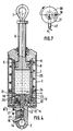
- the device shown comprises a shock absorber body 1, one end of which is intended to be articulated by a pin 2 on the artificial leg (not shown) of a femoral amputee.
- a first cylinder 3 containing a hydraulic fluid 4 and in which a piston 5 moves, the rod 6 of which projects outside the body 1 and is articulated at its end by an axis 7 on the 'socket (not shown) in which is housed the stump of the amputee.
- a reverse arrangement could naturally be adopted, with the body 1 articulated on the case and the rod 6 articulated on the artificial leg.
- the socket and the artificial leg are naturally hinged together in the usual way.
- a second cylinder 8, of annular section, is arranged concentrically with the cylinder 3 and can communicate with the latter, on the one hand, at its upper part, through orifices 9 formed in its side wall, on the other hand, at its lower part, by conduits 10,26,16 opening into the bottom of the cylinder 3, by a manifold 12 and by a conduit 11, opening into the bottom of the cylinder 8.
- the valve 21 can be driven in rotation by a movable pin in rotation or eccentric 17, which is engaged in a recess 18 of the stem 13 of the valve and which projects laterally outside the device.
- the manifold 12 finally communicates via conduits 22 with a cylindrical reservoir 23, of circular section, arranged concentrically with the cylinder 8, the upper part of which is constituted by a movable annular element 24, forming a piston, biased by a spring 25, which, at its other end bears against the upper part of the body 1.
- the valve 21 under the effect of the pressure and the speed of the fluid, is pressed against the bottom of the cylinder 3, closing the orifice of the conduits 16.
- the orifice 19 of the controlled leakage conduit 10 is however in coincidence with the port 20 of the valve, and the hydraulic fluid can therefore continue to use the conduit 10 thereby braking the descent of the piston 5.
- the pressure from which the valve 21 is pressed against the bottom of the cylinder 3 can be adjusted and easily adapted to the degree of autonomy of the person amputated. acting on the adjusting screw 14.
- the device according to the invention therefore brings, in a simple form, significant improvements to the hydraulic regulation devices of the walking of the femoral amputees.
Landscapes
- Health & Medical Sciences (AREA)
- Transplantation (AREA)
- Heart & Thoracic Surgery (AREA)
- Oral & Maxillofacial Surgery (AREA)
- Engineering & Computer Science (AREA)
- Biomedical Technology (AREA)
- Cardiology (AREA)
- Vascular Medicine (AREA)
- Life Sciences & Earth Sciences (AREA)
- Animal Behavior & Ethology (AREA)
- General Health & Medical Sciences (AREA)
- Public Health (AREA)
- Veterinary Medicine (AREA)
- Orthopedic Medicine & Surgery (AREA)
- Prostheses (AREA)
Applications Claiming Priority (2)
| Application Number | Priority Date | Filing Date | Title |
|---|---|---|---|
| FR9202901A FR2688404B1 (fr) | 1992-03-11 | 1992-03-11 | Dispositif de regulation hydraulique de la marche des amputes femoraux. |
| FR9202901 | 1992-03-11 |
Publications (2)
| Publication Number | Publication Date |
|---|---|
| EP0560652A1 true EP0560652A1 (de) | 1993-09-15 |
| EP0560652B1 EP0560652B1 (de) | 1997-08-06 |
Family
ID=9427581
Family Applications (1)
| Application Number | Title | Priority Date | Filing Date |
|---|---|---|---|
| EP93400561A Expired - Lifetime EP0560652B1 (de) | 1992-03-11 | 1993-03-04 | Steuereinrichtung für Oberschenkelprothese |
Country Status (6)
| Country | Link |
|---|---|
| US (1) | US5376138A (de) |
| EP (1) | EP0560652B1 (de) |
| DE (1) | DE69312771T2 (de) |
| DK (1) | DK0560652T3 (de) |
| ES (1) | ES2105148T3 (de) |
| FR (1) | FR2688404B1 (de) |
Cited By (4)
| Publication number | Priority date | Publication date | Assignee | Title |
|---|---|---|---|---|
| WO1994007442A1 (de) * | 1992-10-02 | 1994-04-14 | Biedermann Motech Gmbh | Schwungphasensteuervorrichtung |
| WO1995026171A1 (de) * | 1994-03-28 | 1995-10-05 | Biedermann Motech Gmbh | Schwungphasensteuerung für ein künstliches kniegelenk |
| CN106344228A (zh) * | 2016-08-23 | 2017-01-25 | 国家康复辅具研究中心 | 一种用于假肢关节运动调节的液压弹簧装置 |
| WO2019037776A1 (zh) * | 2017-08-24 | 2019-02-28 | 深圳市罗伯医疗科技有限公司 | 膝关节康复机器人及其控制方法 |
Families Citing this family (42)
| Publication number | Priority date | Publication date | Assignee | Title |
|---|---|---|---|---|
| SE508780C2 (sv) * | 1992-06-09 | 1998-11-02 | Gramtec Innovation Ab | Anordning för dämpning av vridrörelsen vid en led, exempelvis en konstgjord knäled samt konstgjord led innefattande en dylik anordning |
| US5556082A (en) * | 1993-12-07 | 1996-09-17 | Showa Corporation | Cushion unit |
| NL9400733A (nl) * | 1994-05-04 | 1995-12-01 | Ambroise Holland Bv | Prothese. |
| US5702488A (en) | 1995-09-12 | 1997-12-30 | Model & Instrument Development Corporation | Prosthetic pylon having an enclosed compressible volume of fluid to support a patient's weight |
| FR2742505B1 (fr) * | 1995-12-13 | 1998-11-27 | Jean Perret Ets | Amortisseur |
| US5779735A (en) * | 1996-05-17 | 1998-07-14 | Molino; Joseph L. | Knee unit for above-knee prosthetic leg |
| US6835207B2 (en) * | 1996-07-22 | 2004-12-28 | Fred Zacouto | Skeletal implant |
| DE29723632U1 (de) * | 1997-06-26 | 1999-01-07 | Mauch Inc | Computergesteuerte hydraulische Widerstandseinrichtung für eine Prothese und andere Vorrichtungen |
| DE69914730T2 (de) * | 1998-04-10 | 2005-01-27 | Phillips, Van Lehn, Rancho Santa Fe | Stossdämpfungsmodul mit schraubenfeder für prothesen |
| US6511512B2 (en) | 1998-04-10 | 2003-01-28 | Ossur Hf | Active shock module prosthesis |
| GB9823946D0 (en) * | 1998-11-03 | 1998-12-30 | Hammond Richard V | Prosthesis control unit |
| AU778410B2 (en) * | 1999-12-01 | 2004-12-02 | Henry Graf | Intervertebral stabilising device |
| US7066957B2 (en) * | 1999-12-29 | 2006-06-27 | Sdgi Holdings, Inc. | Device and assembly for intervertebral stabilization |
| FR2817461B1 (fr) * | 2000-12-01 | 2003-08-15 | Henry Graf | Dispositif de stabilisation intervertebral |
| GB0119104D0 (en) * | 2001-08-06 | 2001-09-26 | Patterson Noble | Walking aid |
| US7128192B2 (en) | 2001-08-30 | 2006-10-31 | Fox Factory, Inc. | Inertia valve shock absorber |
| US7273137B2 (en) * | 2001-08-30 | 2007-09-25 | Fox Factory, Inc. | Inertia valve shock absorber |
| JP4689267B2 (ja) * | 2002-05-29 | 2011-05-25 | プログレッシブ サスペンション インコーポレイテッド | 圧力調整式制御弁及び遠隔圧力調整装置を備えた油圧式ダンパ |
| US7314490B2 (en) | 2002-08-22 | 2008-01-01 | Victhom Human Bionics Inc. | Actuated leg prosthesis for above-knee amputees |
| US7736394B2 (en) | 2002-08-22 | 2010-06-15 | Victhom Human Bionics Inc. | Actuated prosthesis for amputees |
| US20040068322A1 (en) * | 2002-10-04 | 2004-04-08 | Ferree Bret A. | Reduced-friction artificial joints and components therefor |
| US6911050B2 (en) | 2002-10-23 | 2005-06-28 | Joseph L. Molino | Prosthetic knee unit |
| US6969408B2 (en) * | 2003-09-30 | 2005-11-29 | Ossur Engineering, Inc. | Low profile active shock module prosthesis |
| US7815689B2 (en) | 2003-11-18 | 2010-10-19 | Victhom Human Bionics Inc. | Instrumented prosthetic foot |
| US7637959B2 (en) | 2004-02-12 | 2009-12-29 | össur hf | Systems and methods for adjusting the angle of a prosthetic ankle based on a measured surface angle |
| DE202004008014U1 (de) * | 2004-05-18 | 2004-09-09 | Teko Automation, Mensch Und Technik Gmbh | Schwungphasensteuervorrichtung |
| WO2007016408A1 (en) * | 2005-07-29 | 2007-02-08 | Freedom Innovations, Inc. | Novel computer controlled prosthetic knee device |
| DE102006019858A1 (de) * | 2006-04-28 | 2007-10-31 | Bauerfeind Ag | Knieprothesengelenk |
| WO2008080231A1 (en) | 2007-01-05 | 2008-07-10 | Victhom Human Bionics Inc. | Joint actuation mechanism for a prosthetic and/or orthotic device having a compliant transmission |
| EP2120801B1 (de) | 2007-01-19 | 2018-04-11 | Victhom Laboratory Inc. | Reaktionsschicht-kontrollsystem für prothetische und orthotische vorrichtungen |
| CN102036626B (zh) | 2008-03-24 | 2014-07-02 | 奥瑟Hf公司 | 经股的假肢系统和用于操作该系统的方法 |
| US9060884B2 (en) | 2011-05-03 | 2015-06-23 | Victhom Human Bionics Inc. | Impedance simulating motion controller for orthotic and prosthetic applications |
| US10543109B2 (en) | 2011-11-11 | 2020-01-28 | Össur Iceland Ehf | Prosthetic device and method with compliant linking member and actuating linking member |
| US9532877B2 (en) | 2011-11-11 | 2017-01-03 | Springactive, Inc. | Robotic device and method of using a parallel mechanism |
| US9044346B2 (en) | 2012-03-29 | 2015-06-02 | össur hf | Powered prosthetic hip joint |
| US9561118B2 (en) | 2013-02-26 | 2017-02-07 | össur hf | Prosthetic foot with enhanced stability and elastic energy return |
| WO2014159114A1 (en) | 2013-03-14 | 2014-10-02 | össur hf | Prosthetic ankle: a method of controlling based on adaptation to speed |
| EP3128958B1 (de) | 2014-04-11 | 2019-08-07 | Össur HF | Fussprothese mit abnehmbaren flexiblen elementen |
| DE102016118999B4 (de) | 2016-10-06 | 2018-05-09 | Otto Bock Healthcare Products Gmbh | Aktuator-Dämpfer-Einheit |
| WO2021055851A1 (en) | 2019-09-18 | 2021-03-25 | Össur Iceland Ehf | Methods and systems for controlling a prosthetic or orthotic device |
| CN112741712B (zh) * | 2019-10-31 | 2022-11-08 | 杭州启明医疗器械股份有限公司 | 通过液压方式驱动的介入器械输送系统 |
| DE102020129644A1 (de) | 2020-11-10 | 2022-05-12 | Ottobock Se & Co. Kgaa | Prothesenkniegelenk |
Citations (4)
| Publication number | Priority date | Publication date | Assignee | Title |
|---|---|---|---|---|
| DE724959C (de) * | 1937-05-05 | 1942-09-10 | Istituto Ortopedico Rizzoli | Kniegelenk fuer Beinprothesen mit im Unterschenkel eingebautem OElpumpenzylinder zur Regelung der Gelenkbewegung |
| US3316558A (en) * | 1963-11-12 | 1967-05-02 | La Vaughn L Mortensen | Prosthetic leg with a hydraulic knee control |
| FR1565589A (de) * | 1968-03-18 | 1969-05-02 | ||
| EP0097226A1 (de) * | 1982-06-18 | 1984-01-04 | Otto Bock Orthopädische Industrie Besitz- und Verwaltungs-Kommanditgesellschaft | Hydraulik-Dämpfzylinder und damit aufgebautes künstliches Gelenk |
Family Cites Families (5)
| Publication number | Priority date | Publication date | Assignee | Title |
|---|---|---|---|---|
| DE1075277B (de) * | 1960-02-11 | Ing Hans Adolph Mauch Dayton Ohio Dipl (V St A) | Beinprothese fur Oberschenkelamputierte | |
| US2561370A (en) * | 1948-07-09 | 1951-07-24 | Ulrich K Henschke | Artificial leg with controlled knee locking means |
| FR1077650A (fr) * | 1952-03-26 | 1954-11-10 | Ocram | Amortisseur hydraulique d'oscillations destiné en particulier aux fourches antérieures des motocycles, scooters et analogues |
| SU598608A1 (ru) * | 1974-06-04 | 1978-03-25 | Ilyukhin Vladimir Fedorovich | Протез верхней конечности |
| JPH035224A (ja) * | 1989-05-31 | 1991-01-11 | Chuo Spring Co Ltd | 車輌用スタビライザ装置 |
-
1992
- 1992-03-11 FR FR9202901A patent/FR2688404B1/fr not_active Expired - Fee Related
-
1993
- 1993-03-04 EP EP93400561A patent/EP0560652B1/de not_active Expired - Lifetime
- 1993-03-04 DK DK93400561.2T patent/DK0560652T3/da active
- 1993-03-04 ES ES93400561T patent/ES2105148T3/es not_active Expired - Lifetime
- 1993-03-04 DE DE69312771T patent/DE69312771T2/de not_active Expired - Fee Related
- 1993-03-11 US US08/029,672 patent/US5376138A/en not_active Expired - Fee Related
Patent Citations (4)
| Publication number | Priority date | Publication date | Assignee | Title |
|---|---|---|---|---|
| DE724959C (de) * | 1937-05-05 | 1942-09-10 | Istituto Ortopedico Rizzoli | Kniegelenk fuer Beinprothesen mit im Unterschenkel eingebautem OElpumpenzylinder zur Regelung der Gelenkbewegung |
| US3316558A (en) * | 1963-11-12 | 1967-05-02 | La Vaughn L Mortensen | Prosthetic leg with a hydraulic knee control |
| FR1565589A (de) * | 1968-03-18 | 1969-05-02 | ||
| EP0097226A1 (de) * | 1982-06-18 | 1984-01-04 | Otto Bock Orthopädische Industrie Besitz- und Verwaltungs-Kommanditgesellschaft | Hydraulik-Dämpfzylinder und damit aufgebautes künstliches Gelenk |
Cited By (5)
| Publication number | Priority date | Publication date | Assignee | Title |
|---|---|---|---|---|
| WO1994007442A1 (de) * | 1992-10-02 | 1994-04-14 | Biedermann Motech Gmbh | Schwungphasensteuervorrichtung |
| US5545233A (en) * | 1992-10-02 | 1996-08-13 | Biedermann Motech Gmbh | Swing phase control device |
| WO1995026171A1 (de) * | 1994-03-28 | 1995-10-05 | Biedermann Motech Gmbh | Schwungphasensteuerung für ein künstliches kniegelenk |
| CN106344228A (zh) * | 2016-08-23 | 2017-01-25 | 国家康复辅具研究中心 | 一种用于假肢关节运动调节的液压弹簧装置 |
| WO2019037776A1 (zh) * | 2017-08-24 | 2019-02-28 | 深圳市罗伯医疗科技有限公司 | 膝关节康复机器人及其控制方法 |
Also Published As
| Publication number | Publication date |
|---|---|
| DK0560652T3 (da) | 1998-03-16 |
| FR2688404A1 (fr) | 1993-09-17 |
| DE69312771T2 (de) | 1997-12-11 |
| DE69312771D1 (de) | 1997-09-11 |
| FR2688404B1 (fr) | 1995-07-13 |
| EP0560652B1 (de) | 1997-08-06 |
| US5376138A (en) | 1994-12-27 |
| ES2105148T3 (es) | 1997-10-16 |
Similar Documents
| Publication | Publication Date | Title |
|---|---|---|
| EP0560652B1 (de) | Steuereinrichtung für Oberschenkelprothese | |
| FR2771624A1 (fr) | Prothese de membre inferieur | |
| US6113642A (en) | Computer controlled hydraulic resistance device for a prosthesis and other apparatus | |
| JP3504798B2 (ja) | 制動膝関節 | |
| EP2462901B1 (de) | Prothese für untere Gliedmaßen | |
| WO2014016424A1 (fr) | Systeme hydraulique d'ensemble genou-cheville controle par microprocesseur | |
| EP1603495B1 (de) | Künstlicher kniegelenksmechanismus | |
| WO2000023017A8 (en) | Prosthetic device using a cam-shaped wheel | |
| FR2735018A1 (fr) | Piece prothetique pneumatique pour l'articulation du genou | |
| FR2473670A1 (fr) | Soupape de surete equipee d'un frein hydraulique et frein hydraulique susceptible d'etre insere dans une soupape existante | |
| WO1999000075A1 (en) | Computer controlled hydraulic resistance device for a prosthesis and other apparatus | |
| FR2509829A1 (fr) | Regulateur de pression a commande par solenoide | |
| EP2150380A2 (de) | Durch eine unter druck stehende unkomprimierbare flüssigkeit betätigte schlagvorrichtung | |
| EP0778111B1 (de) | Notausschaltvorrichtung für Roboter | |
| FR2468775A1 (fr) | Distributeur hydraulique | |
| FR2770772A1 (fr) | Prothese de jambe | |
| EP3297578A1 (de) | Verfahren zur regelung einer durch einen mikrocontroller gesteuerten prothese und mit einem mikrocontroller ausgestattete prothese zur durchführung des regelungsverfahren | |
| EP1010825A3 (de) | Ab- und Überlaufgarnitur | |
| WO2003024759A1 (fr) | Maître-cylindre tandem pour systeme de freinage electrohydraulique. | |
| FR2829737A1 (fr) | Maitre-cylindre tandem pour systemes de freinage electrohydraulique | |
| EP3630023A1 (de) | Prothese für oberschenkelamputierte | |
| EP0449679B1 (de) | Bremsdruckregler mit Zusatzventil | |
| US5021065A (en) | Rotationally actuated prosthetic helping hand | |
| EP0354085B1 (de) | Lastabhängig gesteuertes Proportionierventil für die Zweikreisbremsanlage eines Kraftfahrzeuges | |
| FR2746154A1 (fr) | Frein a commande hydropneumatique |
Legal Events
| Date | Code | Title | Description |
|---|---|---|---|
| PUAI | Public reference made under article 153(3) epc to a published international application that has entered the european phase |
Free format text: ORIGINAL CODE: 0009012 |
|
| AK | Designated contracting states |
Kind code of ref document: A1 Designated state(s): BE DE DK ES FR GB IT NL SE |
|
| 17P | Request for examination filed |
Effective date: 19931004 |
|
| 17Q | First examination report despatched |
Effective date: 19950727 |
|
| GRAG | Despatch of communication of intention to grant |
Free format text: ORIGINAL CODE: EPIDOS AGRA |
|
| GRAH | Despatch of communication of intention to grant a patent |
Free format text: ORIGINAL CODE: EPIDOS IGRA |
|
| GRAH | Despatch of communication of intention to grant a patent |
Free format text: ORIGINAL CODE: EPIDOS IGRA |
|
| GRAA | (expected) grant |
Free format text: ORIGINAL CODE: 0009210 |
|
| AK | Designated contracting states |
Kind code of ref document: B1 Designated state(s): BE DE DK ES FR GB IT NL SE |
|
| REF | Corresponds to: |
Ref document number: 69312771 Country of ref document: DE Date of ref document: 19970911 |
|
| GBT | Gb: translation of ep patent filed (gb section 77(6)(a)/1977) |
Effective date: 19970828 |
|
| REG | Reference to a national code |
Ref country code: ES Ref legal event code: FG2A Ref document number: 2105148 Country of ref document: ES Kind code of ref document: T3 |
|
| REG | Reference to a national code |
Ref country code: DK Ref legal event code: T3 |
|
| PLBE | No opposition filed within time limit |
Free format text: ORIGINAL CODE: 0009261 |
|
| STAA | Information on the status of an ep patent application or granted ep patent |
Free format text: STATUS: NO OPPOSITION FILED WITHIN TIME LIMIT |
|
| 26N | No opposition filed | ||
| REG | Reference to a national code |
Ref country code: GB Ref legal event code: IF02 |
|
| PGFP | Annual fee paid to national office [announced via postgrant information from national office to epo] |
Ref country code: GB Payment date: 20030314 Year of fee payment: 11 |
|
| PGFP | Annual fee paid to national office [announced via postgrant information from national office to epo] |
Ref country code: SE Payment date: 20030318 Year of fee payment: 11 Ref country code: NL Payment date: 20030318 Year of fee payment: 11 |
|
| PGFP | Annual fee paid to national office [announced via postgrant information from national office to epo] |
Ref country code: DK Payment date: 20030320 Year of fee payment: 11 |
|
| PGFP | Annual fee paid to national office [announced via postgrant information from national office to epo] |
Ref country code: ES Payment date: 20030326 Year of fee payment: 11 |
|
| PGFP | Annual fee paid to national office [announced via postgrant information from national office to epo] |
Ref country code: BE Payment date: 20030423 Year of fee payment: 11 |
|
| PG25 | Lapsed in a contracting state [announced via postgrant information from national office to epo] |
Ref country code: GB Free format text: LAPSE BECAUSE OF NON-PAYMENT OF DUE FEES Effective date: 20040304 |
|
| PG25 | Lapsed in a contracting state [announced via postgrant information from national office to epo] |
Ref country code: SE Free format text: LAPSE BECAUSE OF NON-PAYMENT OF DUE FEES Effective date: 20040305 Ref country code: ES Free format text: LAPSE BECAUSE OF NON-PAYMENT OF DUE FEES Effective date: 20040305 |
|
| PG25 | Lapsed in a contracting state [announced via postgrant information from national office to epo] |
Ref country code: DK Free format text: LAPSE BECAUSE OF NON-PAYMENT OF DUE FEES Effective date: 20040331 Ref country code: BE Free format text: LAPSE BECAUSE OF NON-PAYMENT OF DUE FEES Effective date: 20040331 |
|
| BERE | Be: lapsed |
Owner name: ETS *PROTEOR Effective date: 20040331 |
|
| PG25 | Lapsed in a contracting state [announced via postgrant information from national office to epo] |
Ref country code: NL Free format text: LAPSE BECAUSE OF NON-PAYMENT OF DUE FEES Effective date: 20041001 |
|
| GBPC | Gb: european patent ceased through non-payment of renewal fee | ||
| EUG | Se: european patent has lapsed | ||
| NLV4 | Nl: lapsed or anulled due to non-payment of the annual fee |
Effective date: 20041001 |
|
| PG25 | Lapsed in a contracting state [announced via postgrant information from national office to epo] |
Ref country code: IT Free format text: LAPSE BECAUSE OF NON-PAYMENT OF DUE FEES;WARNING: LAPSES OF ITALIAN PATENTS WITH EFFECTIVE DATE BEFORE 2007 MAY HAVE OCCURRED AT ANY TIME BEFORE 2007. THE CORRECT EFFECTIVE DATE MAY BE DIFFERENT FROM THE ONE RECORDED. Effective date: 20050304 |
|
| REG | Reference to a national code |
Ref country code: ES Ref legal event code: FD2A Effective date: 20040305 |
|
| PGFP | Annual fee paid to national office [announced via postgrant information from national office to epo] |
Ref country code: DE Payment date: 20070316 Year of fee payment: 15 |
|
| PGFP | Annual fee paid to national office [announced via postgrant information from national office to epo] |
Ref country code: FR Payment date: 20070129 Year of fee payment: 15 |
|
| REG | Reference to a national code |
Ref country code: FR Ref legal event code: ST Effective date: 20081125 |
|
| PG25 | Lapsed in a contracting state [announced via postgrant information from national office to epo] |
Ref country code: DE Free format text: LAPSE BECAUSE OF NON-PAYMENT OF DUE FEES Effective date: 20081001 |
|
| PG25 | Lapsed in a contracting state [announced via postgrant information from national office to epo] |
Ref country code: FR Free format text: LAPSE BECAUSE OF NON-PAYMENT OF DUE FEES Effective date: 20080331 |