EP0560743A1 - Controlled-deformation spacer for anchoring road metal sheet strips or guardrails - Google Patents
Controlled-deformation spacer for anchoring road metal sheet strips or guardrails Download PDFInfo
- Publication number
- EP0560743A1 EP0560743A1 EP93830097A EP93830097A EP0560743A1 EP 0560743 A1 EP0560743 A1 EP 0560743A1 EP 93830097 A EP93830097 A EP 93830097A EP 93830097 A EP93830097 A EP 93830097A EP 0560743 A1 EP0560743 A1 EP 0560743A1
- Authority
- EP
- European Patent Office
- Prior art keywords
- safety device
- metal sheet
- guardrails
- arm
- support
- Prior art date
- Legal status (The legal status is an assumption and is not a legal conclusion. Google has not performed a legal analysis and makes no representation as to the accuracy of the status listed.)
- Withdrawn
Links
- 125000006850 spacer group Chemical group 0.000 title claims abstract description 39
- 239000002184 metal Substances 0.000 title claims abstract description 18
- 238000004873 anchoring Methods 0.000 title claims abstract description 12
- 230000003313 weakening effect Effects 0.000 claims description 9
- 238000010276 construction Methods 0.000 claims description 8
- 238000006073 displacement reaction Methods 0.000 claims description 2
- 230000001419 dependent effect Effects 0.000 claims 1
- 238000007493 shaping process Methods 0.000 claims 1
- 230000004888 barrier function Effects 0.000 description 18
- 230000005484 gravity Effects 0.000 description 3
- 238000013016 damping Methods 0.000 description 2
- 230000000694 effects Effects 0.000 description 2
- 230000007935 neutral effect Effects 0.000 description 2
- 238000010521 absorption reaction Methods 0.000 description 1
- 238000005452 bending Methods 0.000 description 1
- 238000000034 method Methods 0.000 description 1
- 238000012986 modification Methods 0.000 description 1
- 230000004048 modification Effects 0.000 description 1
- 238000005381 potential energy Methods 0.000 description 1
- 238000011084 recovery Methods 0.000 description 1
- 230000000630 rising effect Effects 0.000 description 1
- 238000005728 strengthening Methods 0.000 description 1
- 238000011144 upstream manufacturing Methods 0.000 description 1
Images




Classifications
-
- E—FIXED CONSTRUCTIONS
- E01—CONSTRUCTION OF ROADS, RAILWAYS, OR BRIDGES
- E01F—ADDITIONAL WORK, SUCH AS EQUIPPING ROADS OR THE CONSTRUCTION OF PLATFORMS, HELICOPTER LANDING STAGES, SIGNS, SNOW FENCES, OR THE LIKE
- E01F15/00—Safety arrangements for slowing, redirecting or stopping errant vehicles, e.g. guard posts or bollards; Arrangements for reducing damage to roadside structures due to vehicular impact
- E01F15/02—Continuous barriers extending along roads or between traffic lanes
- E01F15/04—Continuous barriers extending along roads or between traffic lanes essentially made of longitudinal beams or rigid strips supported above ground at spaced points
- E01F15/0407—Metal rails
- E01F15/0438—Spacers between rails and posts, e.g. energy-absorbing means
Definitions
- the present invention relates to road safety barriers or guardrails and more specifically to an improved system for anchoring the road metal sheet strip or guardrail to the support stakes so as to absorb and dissipate the energy produced by the impact of a vehicle and to keep the strip in an operative position even in case of collision with heavy vehicles.
- spacing cantilevers which are weakened by less withstanding zones designed to deform in a differential way so as to cause the adjoining portions to reciprocally rotate and/or to longitudinally slide upon collision according to the stress to which the spacer is subjected. i.e. according to the impact strength.
- Road safety barriers must contain within the road limits always heavier, taller and relatively faster vehicles. while minimizing the damages to passengers of small vehicles due to impact against such barriers.
- the problem involves the components of forces and deformations perpendicular to the road axis and is usually dealt with and solved in different ways, which also take into account available space, so that the range of proposed constructions is extremely wide.
- the ropes are replaced with metal sheet strips supported by members having poor transversal rigidity so that the strip sections are subjected to tensile strength, thus giving rise to a rope effect.
- Some of the proposed solutions address the problem of containing heavy vehicles having a high center of gravity, while protecting the environment using constructions of reduced height; all this taking into account whether such constructions are to be used as lateral barriers or traffic island barriers to be installed at the central island between two tracks.
- FIG. 1 a shows a side view of a barrier before an impact
- Fig. 1 b shows the same barrier after an impact from the right hand to the left hand side of the observer.
- the barrier is formed by a strip 1, stakes 2, and a connection arm or spacer 3, and can be used as a lateral guardrail or as traffic island guardrail (in which case the spacer is of the double type and includes also portion 3' supporting strips 1'.
- Italian Patent Application No. 8912482 discloses a device of the above-mentioned type in which the strip of the guardrail is connected to the spacer, which secures it to the support stake, by means of an energy-recovery damping system.
- a similar system is used for connecting spacer to support stake so as to form a controlled four-bar-linkage with the preceding system.
- the strip In case of a collision of particular intensity the strip is raised and takes on a position transversal to the original orientation.
- the spacer is in turn shaped so that it is bent upwards in case of a particularly strong collision to cause such strip to further raise so as to assure heavy vehicles such as trailer-trucks having a high centre of gravity to be kept back from the guardrail.
- the system is rat her complex both as far as construction and assembly is concerned since each support stake requires the combination of a spacer and two separate energy dissipators.
- the present invention seeks to provide simplified supports for safety barriers or guardrails of the above-mentioned type and to reduce the cost and the assembly time thereof by utilizing the spacer itself as a damping system for absorbing energy, and at the same time taking advantage of the deformation of such assembly to ensure that the strip assumes an operative position under any circumstance.
- Another goal of the present invention is to provide a spacer for connecting the strip of a safety barrier or guardrail of the above-mentioned type so that such spacer can undergo a controlled deformation, ab- sorbe energy as a function of the intensity of impact, and raise the strip upwards according to such intensity.
- the inventive step of the present invention is that of weakening the spacer by means of a combination of weaker controlled-deformation zones, each of which, upon being crushed, results in the adjoining parts to reciprocally rotate or slide.
- Figs. 3 and 4 show a side and a front view of a preferred embodiment of the support arm for a conventional double-corrugation strip, respectively;
- a rigid arm 6 is weakened at a certain zone by a slot 8.
- the slot shown by a shading, has the form of a right triangle with the vertex pointing downwards.
- the impact force shown by the arrow "p" moves portion 10 of the arm upwards from position GABC to position G'A'BC as side FG of slot 8 is deliberately weaker than sides FC and CG.
- p the impact force shown by the arrow "p" moves portion 10 of the arm upwards from position GABC to position G'A'BC as side FG of slot 8 is deliberately weaker than sides FC and CG.
- slots Similar remarks may be made in relation to a number of slots of different shapes and to their combination, whereby a raising of the arm corresponding to a rotation about a virtual fulcrum can be achieved.
- slot has been used for ease of understanding of the concept of weaker zones and that in the above examples, the slots correspond to the entire weaker zone. However, the slots can be restricted only to a portion of the zones intended to be deformed.
- the weakening be effected in such a way as to minimize the risk of a deflection of the spacers in the plane parallel to the road (rotations about the axes of the stakes).
- the weakest zone (intended to cause great defomations at low strain) will occur preferably at the end of the spacer near the strip, while the relative strenghth of the weak zones increases as they near the stakes.
- the weakening will be preferably made near the vertical neutral axis; to this end it is preferable that the spacer be designed so that such neutral axis corresponds to or is near the surface to be weakened (for example: the core of a I or Z -section).
- the combination of the shaped slots 14, 16 with holes 20, 22 and 24, 26 forms two weakened zones the effects of which are equivalent to those caused by a pair of triangular slots as shown in Fig. 2d.
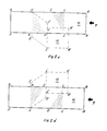
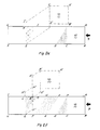
- the succession of deformations shown in Figs. 7a, 7b, 7c, and 7d is as follows: the crushing of slot 14 causes the end of the arm where the barrier strip is bolted to rotate about a virtual fulcrum I, while the crushing of slot 16 causes portion 34 to rotate about a second virtual fulcrum II so as to partially compensate for the rotation about I. Finally, the crushing of slot 18 causes an upward displacement of the section of the arm at the right thereof and a further lifting of the barrier strip.
- Figs. 7b and 7d showthatthe deformations never occur consecutively at each controlled zone but may be caused simultaneously according to a predetermined strain resistance.
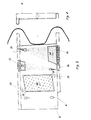
- spacer arm 36 has the shape of an inclined L, which allows the two strips 38, 40 to be secured independently at different heights and in staggered positions.
- Arm 36 has a plurality of weakening slots 42, 44, 46, 48 distributed both along the horizontal flange and the vertical flange of the L-section.
- the lower strip is intended to take up alone the impactofa a light vehicle with poorrigidity, while both strips are intended together to take up the impact of heavy vehicles: first the lower strip 38 and then also the upper strip 40 after lower strip 38 is raised and aligned with strip 40.
- the sequences is apparent in Figs. 8a, 8b and 8c.
- the weaker zones can be formed not only by weakening the construction in such areas but alternatively by strengthening other zones.
Landscapes
- Engineering & Computer Science (AREA)
- Architecture (AREA)
- Civil Engineering (AREA)
- Structural Engineering (AREA)
- Refuge Islands, Traffic Blockers, Or Guard Fence (AREA)
Applications Claiming Priority (2)
| Application Number | Priority Date | Filing Date | Title |
|---|---|---|---|
| ITRM920175 | 1992-03-12 | ||
| ITRM920175A IT1258389B (it) | 1992-03-12 | 1992-03-12 | Elemento distanziatore a deformazione programmata per l'ancoraggio in opera di nastri o correnti di barriere stradali di sicurezza. |
Publications (1)
| Publication Number | Publication Date |
|---|---|
| EP0560743A1 true EP0560743A1 (en) | 1993-09-15 |
Family
ID=11400809
Family Applications (1)
| Application Number | Title | Priority Date | Filing Date |
|---|---|---|---|
| EP93830097A Withdrawn EP0560743A1 (en) | 1992-03-12 | 1993-03-11 | Controlled-deformation spacer for anchoring road metal sheet strips or guardrails |
Country Status (2)
| Country | Link |
|---|---|
| EP (1) | EP0560743A1 (it) |
| IT (1) | IT1258389B (it) |
Cited By (1)
| Publication number | Priority date | Publication date | Assignee | Title |
|---|---|---|---|---|
| DE102011055959A1 (de) * | 2011-12-02 | 2013-06-06 | Heintzmann Sicherheitssysteme Gmbh & Co. Kg | Fahrzeugrückhaltesystem |
Citations (7)
| Publication number | Priority date | Publication date | Assignee | Title |
|---|---|---|---|---|
| LU41713A1 (it) * | 1962-05-15 | 1962-07-16 | ||
| FR1584411A (it) * | 1967-08-29 | 1969-12-19 | ||
| US3981486A (en) * | 1972-01-31 | 1976-09-21 | Ernst Baumann | Shock absorber and guide rail assembly including the same |
| DE2642475A1 (de) * | 1975-10-14 | 1977-04-21 | Voest Ag | Leitplanke |
| US4138093A (en) * | 1977-05-18 | 1979-02-06 | Meinzer Lester N | Guard rail cell |
| FR2401274A1 (fr) * | 1977-08-17 | 1979-03-23 | Ut Vasuttervezoe Vallalat | Dispositif de protection, notamment pour routes |
| EP0356686A1 (en) * | 1988-08-03 | 1990-03-07 | METALMECCANICA FRACASSO S.p.A. | Guardrail barrier |
-
1992
- 1992-03-12 IT ITRM920175A patent/IT1258389B/it active IP Right Grant
-
1993
- 1993-03-11 EP EP93830097A patent/EP0560743A1/en not_active Withdrawn
Patent Citations (7)
| Publication number | Priority date | Publication date | Assignee | Title |
|---|---|---|---|---|
| LU41713A1 (it) * | 1962-05-15 | 1962-07-16 | ||
| FR1584411A (it) * | 1967-08-29 | 1969-12-19 | ||
| US3981486A (en) * | 1972-01-31 | 1976-09-21 | Ernst Baumann | Shock absorber and guide rail assembly including the same |
| DE2642475A1 (de) * | 1975-10-14 | 1977-04-21 | Voest Ag | Leitplanke |
| US4138093A (en) * | 1977-05-18 | 1979-02-06 | Meinzer Lester N | Guard rail cell |
| FR2401274A1 (fr) * | 1977-08-17 | 1979-03-23 | Ut Vasuttervezoe Vallalat | Dispositif de protection, notamment pour routes |
| EP0356686A1 (en) * | 1988-08-03 | 1990-03-07 | METALMECCANICA FRACASSO S.p.A. | Guardrail barrier |
Cited By (1)
| Publication number | Priority date | Publication date | Assignee | Title |
|---|---|---|---|---|
| DE102011055959A1 (de) * | 2011-12-02 | 2013-06-06 | Heintzmann Sicherheitssysteme Gmbh & Co. Kg | Fahrzeugrückhaltesystem |
Also Published As
| Publication number | Publication date |
|---|---|
| ITRM920175A1 (it) | 1993-09-12 |
| ITRM920175A0 (it) | 1992-03-12 |
| IT1258389B (it) | 1996-02-26 |
Similar Documents
| Publication | Publication Date | Title |
|---|---|---|
| US5876020A (en) | High-performance deformable steel guardrail | |
| AU779020B2 (en) | A rail vehicle having a driver's cab provided with an energy-absorbing structure adapted to cope with a collision above the frame of the vehicle | |
| EP0042645B2 (en) | Obstacle protection arrangement | |
| EP1710353A1 (en) | Deformable separator device | |
| CN101138981A (zh) | 轨道车辆 | |
| KR20010024552A (ko) | 차량용 비임 | |
| KR101658915B1 (ko) | 도로안전시설용 차량 충격흡수장치 | |
| EP0554864A1 (en) | A semi-rigid road barrier providing controlled dissipation of impact energy and attitude correction | |
| US4501411A (en) | Guardrail for roadway | |
| CN212175612U (zh) | 车行道双向缓冲防撞护栏 | |
| KR20190073193A (ko) | 충격흡수 고정수단이 구비된 차량 방호울타리 | |
| CN116927120B (zh) | 一种高速公路缓冲防撞护栏板及其使用方法 | |
| KR102227635B1 (ko) | 충돌 슬립에 대한 가이드패널의 가변 저항수단을 구비한 차량 충격흡수장치 | |
| KR102189073B1 (ko) | 칸막이 지지대의 충돌 슬립에 대한 가변 저항수단을 구비한 차량 충격흡수장치 | |
| GB2148358A (en) | Car park buffer | |
| US6551012B1 (en) | Guard rail construction | |
| ES2301730T3 (es) | Sistema de retencion de vehiculos. | |
| KR100682791B1 (ko) | 차량용 방호 울타리 | |
| JP2906013B2 (ja) | ガードフェンス | |
| CN211364468U (zh) | 用于道路维护设备上的多级缓冲防撞装置 | |
| KR100560732B1 (ko) | 회전마찰재를 이용한 충격 흡수장치 | |
| KR200347251Y1 (ko) | 회전마찰재를 이용한 충격 흡수장치 | |
| GB2411631A (en) | Shock absorbing girder for supporting a railway vehicle body | |
| CN221566957U (zh) | 一种交通运输防撞装置 | |
| CN221297677U (zh) | 一种减震型钢筋混凝土护栏 |
Legal Events
| Date | Code | Title | Description |
|---|---|---|---|
| PUAI | Public reference made under article 153(3) epc to a published international application that has entered the european phase |
Free format text: ORIGINAL CODE: 0009012 |
|
| AK | Designated contracting states |
Kind code of ref document: A1 Designated state(s): AT BE CH DE ES FR GB GR LI PT |
|
| 17P | Request for examination filed |
Effective date: 19940311 |
|
| STAA | Information on the status of an ep patent application or granted ep patent |
Free format text: STATUS: THE APPLICATION IS DEEMED TO BE WITHDRAWN |
|
| 18D | Application deemed to be withdrawn |
Effective date: 19961001 |