EP0560921B1 - Procede de reconnaissance de combustion anormale dans un cylindre d'un moteur a combustion interne - Google Patents
Procede de reconnaissance de combustion anormale dans un cylindre d'un moteur a combustion interne Download PDFInfo
- Publication number
- EP0560921B1 EP0560921B1 EP92902581A EP92902581A EP0560921B1 EP 0560921 B1 EP0560921 B1 EP 0560921B1 EP 92902581 A EP92902581 A EP 92902581A EP 92902581 A EP92902581 A EP 92902581A EP 0560921 B1 EP0560921 B1 EP 0560921B1
- Authority
- EP
- European Patent Office
- Prior art keywords
- crankshaft
- cylinder
- speed
- rotational
- combustion engine
- Prior art date
- Legal status (The legal status is an assumption and is not a legal conclusion. Google has not performed a legal analysis and makes no representation as to the accuracy of the status listed.)
- Expired - Lifetime
Links
- 238000002485 combustion reaction Methods 0.000 title claims abstract description 28
- 230000002159 abnormal effect Effects 0.000 title claims abstract description 13
- 238000000034 method Methods 0.000 title claims description 17
- 238000012935 Averaging Methods 0.000 claims description 2
- 230000001133 acceleration Effects 0.000 description 4
- 238000011156 evaluation Methods 0.000 description 4
- 238000012360 testing method Methods 0.000 description 4
- 238000010586 diagram Methods 0.000 description 3
- 238000001514 detection method Methods 0.000 description 2
- 238000002347 injection Methods 0.000 description 2
- 239000007924 injection Substances 0.000 description 2
- 238000005457 optimization Methods 0.000 description 2
- 230000001419 dependent effect Effects 0.000 description 1
- 238000011161 development Methods 0.000 description 1
- 230000018109 developmental process Effects 0.000 description 1
- 238000003745 diagnosis Methods 0.000 description 1
- 238000010304 firing Methods 0.000 description 1
- 230000001788 irregular Effects 0.000 description 1
- 239000000203 mixture Substances 0.000 description 1
- 230000000630 rising effect Effects 0.000 description 1
- 239000000243 solution Substances 0.000 description 1
Images
Classifications
-
- G—PHYSICS
- G01—MEASURING; TESTING
- G01M—TESTING STATIC OR DYNAMIC BALANCE OF MACHINES OR STRUCTURES; TESTING OF STRUCTURES OR APPARATUS, NOT OTHERWISE PROVIDED FOR
- G01M15/00—Testing of engines
- G01M15/04—Testing internal-combustion engines
- G01M15/11—Testing internal-combustion engines by detecting misfire
Definitions
- the invention relates to a method for detecting abnormal burns in a cylinder of an internal combustion engine according to the preamble of claim 1.
- crankshaft positions with the lowest and highest crankshaft speeds must be determined experimentally on this engine test bench. They are, in particular, dependent on the load and speed and are stored in this manner in the control unit for carrying out the method.
- the object of the present invention is therefore to develop the method in such a way that the evaluability is improved.
- the invention is based on the knowledge that the evaluation problems result from the selection of the optimization strategy for the crankshaft positions. In the prior art, those crankshaft positions are sought at which the crankshaft has the lowest or highest speed.
- crankshaft positions are determined during normal operation of the internal combustion engine, so that a statement about the torque generated by it can be derived. In the case of faults that occur strongly in certain load and speed ranges, however, the determined speed difference at the two crankshaft positions is often no longer sufficient.
- this speed difference is therefore increased in that the crankshaft positions are not optimized for the case of normal operation, but rather for the case of abnormal combustion.
- the second crankshaft position is selected later than would correspond to the point of the highest crankshaft speed in normal operation.
- Figure 1 shows an internal combustion engine B with a crankshaft encoder KWG and a camshaft encoder NWG.
- the crankshaft sensor scans a gear wheel connected to the crankshaft, which has a reference mark and a large number of teeth.
- the crankshaft encoder KWG supplies one pulse per tooth and a distinguishable reference pulse at the reference mark as the output signal.
- This output signal is fed to a control unit S which, on the one hand, determines the position of the crankshaft within a 360 ° rotation by counting the pulses and, on the other hand, determines the speed by the chronological sequence of the pulses per time.
- the NWG camshaft sensor scans a gear connected to the camshaft, which has a tooth over half of its circumference and a gap over the other half of its circumference.
- the output signal of the NWG camshaft sender has two states, depending on whether the tooth or the gap is opposite the NWG camshaft sender.
- the control unit S uses this output signal together with the output signal of the crankshaft encoder KWG to determine the cylinder assignment and the crankshaft angle.
- a NWG camshaft sensor is needed because e.g. In the case of a 6-cylinder engine, there is a periodicity of two revolutions each and therefore the position of the crankshaft alone is not sufficient for a clear assignment in the firing order.
- the control unit S essentially has the task of controlling the ignition and injection for the internal combustion engine B and of performing various diagnostic functions. For this purpose, various sensors and actuators, not shown here, are connected to the control unit S.
- Such a control device S thus represents a conventional engine control system, as is already implemented in a large number of vehicles today.
- a diagnostic function carried out by the control unit S is the detection of irregular combustion in one of the cylinders of the internal combustion engine B.
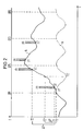
- the reciprocal speed T of the crankshaft is plotted against the crankshaft position z in the diagram in FIG.
- the reciprocal The speed was selected because a corresponding signal is already present in the control unit S.
- the situation is reversed when the speed is considered. Therefore, a rising edge means a slowdown and a falling edge means an acceleration of the crankshaft.
- a normal curve N shows this course for the normal operation of the internal combustion engine B.
- the sinusoidal curve results from the various work cycles of the internal combustion engine B, the individual acceleration phases each being after the ignition of a cylinder during its work cycle.
- the top dead centers of the cylinders 1, 5, 3, 6 are shown by way of example in accordance with the ignition sequence in a 6-cylinder engine.
- FIG. 2 The conditions which occur when proper ignition and combustion of the mixture do not take place during the work cycle of a cylinder are shown in FIG. 2 for cylinder 1.
- a misfire curve A applies in the event that no combustion takes place at all. Accordingly, the crankshaft is not accelerated, but is further slowed down by the machine's resistances. The crankshaft is then accelerated again only after ignition of the next cylinder 5 with proper combustion.
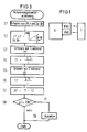
- a corresponding program is stored in a diagnosis routine of the control unit S and is carried out continuously for each cylinder.
- crankshaft positions z1, z2 are defined. These crankshaft positions z1, z2 are usually after the top dead center, are different depending on the load and speed and are optimized by tests. It is essential that the normal case according to the normal curve N is used, but the case of an abnormal combustion, in the example the misfire according to the misfire curve A.
- step S1 of FIG. 3 the air mass LM, the speed n and the cylinder number of the cylinder which is the next to reach its top dead center are recorded. These variables are also used for the purposes of ignition timing and injection time calculation, so that they are already present in control unit S and can be adopted from the corresponding program routines.
- step S2 the crankshaft positions z1, z2 depending on the air mass LM, the rotational speed n and the cylinder number are then taken from corresponding characteristic diagrams.
- the cylinder-specific dependency via the cylinder number is necessary to take the vibration behavior of the crankshaft into account.
- the corresponding reciprocal speeds T1, T2 in the crankshaft positions z1 and z2 are not only recorded once, but in crankshaft position ranges za, for example around the crankshaft positions z1, z2.
- the reciprocal speeds T1 and T2, which correspond to the reciprocal speeds in the two crankshaft positions z1 and z2, are finally obtained from the averaging of the i reciprocal speed Ti detected in each case. This process is carried out in steps S3, S4 and S5, 56.
- step S7 the difference ⁇ T is then calculated from the reciprocal speeds T1 and T2.
- This difference ⁇ T is a direct measure of the acceleration of the crankshaft caused by proper combustion.
- the choice of the limit value GW determines which degree of abnormal combustion should still be recognizable.
- a particularly simple method for the detection of full misfires would be e.g. a pure sign evaluation of the difference ⁇ T.
- FIG. 2 shows that there is a negative difference ⁇ T in the case of the misfiring cylinder 1 and a positive difference in the case of the burning cylinder 5.
- the limit value GW is set to a certain positive value. In this way, burns are also recognized as abnormal which, although they contribute to acceleration, are insufficient compared to that in normal combustion. Such poor combustion would provide a curve that lies between the misfire curve A and the normal curve N.
Landscapes
- Chemical & Material Sciences (AREA)
- Engineering & Computer Science (AREA)
- Combustion & Propulsion (AREA)
- Physics & Mathematics (AREA)
- General Physics & Mathematics (AREA)
- Combined Controls Of Internal Combustion Engines (AREA)
- Testing Of Engines (AREA)
Abstract
Claims (5)
- Procédé pour identifier des vibrations anormales dans un cylindre d'un moteur à combustion interne (B),
la vitesse de rotation du moteur à combustion interne (B) étant déterminée en deux positions (z1, z2) du vilebrequin, qui sont choisies différemment en fonction de la charge et de la vitesse de rotation,
caractérisé par le fait
que les deux positions (z1, z2) du vilebrequin sont choisies de telle sorte que, par rapport au cas d'une combustion anormale, on obtient une différence aussi grande que possible des vitesses de rotation, et
qu'une combustion anormale est identifiée lorsque, respectivement en fonction d'une différence choisie des vitesses de rotation, à savoir une valeur ultérieure de la vitesse de rotation moins une valeur antérieure de la vitesse de rotation ou une valeur antérieure de la vitesse de rotation moins une valeur ultérieure de la vitesse de rotation, une valeur limite (GW) est dépassée par valeurs inférieures ou par valeurs supérieures. - Procédé suivant la revendication 1, caractérisé par le fait que les positions (z1, z2) du vilebrequin sont choisies d'une manière rapportée au cas d'un raté de combustion.
- Procédé suivant la revendication 1, caractérisé par le fait que la vitesse de rotation est déterminée en permanence pour chaque cylindre sur deux zones de positions du vilebrequin et l'une des deux vitesses de rotation est obtenue à partir de là, respectivement par formation de la moyenne.
- Procédé suivant la revendication 1, caractérisé par le fait que la valeur limite (GW) est nulle et que son dépassement par valeurs supérieures ou par valeurs inférieures est identifié au signe de la différence entre les vitesses de rotation.
- Procédé suivant la revendication 1, caractérisé par le fait que les positions (z1, z2) du vilebrequin sont choisies différentes d'une manière spécifique au cylindre.
Applications Claiming Priority (3)
| Application Number | Priority Date | Filing Date | Title |
|---|---|---|---|
| EP90123132 | 1990-12-03 | ||
| EP90123132 | 1990-12-03 | ||
| PCT/EP1991/002157 WO1992009875A1 (fr) | 1990-12-03 | 1991-11-15 | Procede de reconnaissance de combustion anormale dans un cylindre d'un moteur a combustion interne |
Publications (2)
| Publication Number | Publication Date |
|---|---|
| EP0560921A1 EP0560921A1 (fr) | 1993-09-22 |
| EP0560921B1 true EP0560921B1 (fr) | 1994-08-24 |
Family
ID=8204791
Family Applications (1)
| Application Number | Title | Priority Date | Filing Date |
|---|---|---|---|
| EP92902581A Expired - Lifetime EP0560921B1 (fr) | 1990-12-03 | 1991-11-15 | Procede de reconnaissance de combustion anormale dans un cylindre d'un moteur a combustion interne |
Country Status (5)
| Country | Link |
|---|---|
| US (1) | US5394742A (fr) |
| EP (1) | EP0560921B1 (fr) |
| JP (1) | JPH06503167A (fr) |
| DE (1) | DE59102668D1 (fr) |
| WO (1) | WO1992009875A1 (fr) |
Families Citing this family (7)
| Publication number | Priority date | Publication date | Assignee | Title |
|---|---|---|---|---|
| JPH04109062A (ja) * | 1990-08-28 | 1992-04-10 | Hitachi Ltd | 内燃機関の異常燃焼検出装置および内燃機関のトルク制御装置 |
| DE59205867D1 (de) * | 1992-06-30 | 1996-05-02 | Siemens Ag | Verfahren zur Erkennung von Verbrennungsaussetzern |
| JP3441812B2 (ja) * | 1994-09-08 | 2003-09-02 | 本田技研工業株式会社 | 内燃エンジンの燃焼状態検出装置 |
| US5531108A (en) * | 1995-04-05 | 1996-07-02 | Ford Motor Company | Adaptive correction of torsional and wheel profile position irregularities for misfire detection |
| US5528931A (en) * | 1995-04-05 | 1996-06-25 | Ford Motor Company | Engine diagnostic monitor with on-board adjustment of correction factors |
| US5771482A (en) * | 1995-12-15 | 1998-06-23 | The Ohio State University | Estimation of instantaneous indicated torque in multicylinder engines |
| DE19637094C2 (de) * | 1996-09-12 | 2001-02-08 | Mannesmann Vdo Ag | Verfahren zum Bestimmen von Verbrennungsaussetzern |
Citations (2)
| Publication number | Priority date | Publication date | Assignee | Title |
|---|---|---|---|---|
| DE2507138A1 (de) * | 1975-02-19 | 1976-09-02 | Bosch Gmbh Robert | Verfahren und vorrichtung zur gewinnung einer die annaeherung an eine vorgegebene magerlaufgrenze angebenden messgroesse |
| US4697561A (en) * | 1985-04-15 | 1987-10-06 | Purdue Research Foundation | On-line engine torque and torque fluctuation measurement for engine control utilizing crankshaft speed fluctuations |
Family Cites Families (3)
| Publication number | Priority date | Publication date | Assignee | Title |
|---|---|---|---|---|
| US3972230A (en) * | 1975-06-19 | 1976-08-03 | Rca Corporation | Detecting malfunction in cylinders of internal combustion engines |
| US5197325A (en) * | 1990-06-05 | 1993-03-30 | Nissan Motor Company, Limited | Misfiring detection system for internal combustion engines |
| US5191788A (en) * | 1990-11-28 | 1993-03-09 | Mitsubishi Denki Kabushiki Kaisha | Misfire detection device for an internal combustion engine |
-
1991
- 1991-11-15 JP JP4500292A patent/JPH06503167A/ja active Pending
- 1991-11-15 DE DE59102668T patent/DE59102668D1/de not_active Expired - Lifetime
- 1991-11-15 EP EP92902581A patent/EP0560921B1/fr not_active Expired - Lifetime
- 1991-11-15 WO PCT/EP1991/002157 patent/WO1992009875A1/fr not_active Ceased
- 1991-11-15 US US08/066,171 patent/US5394742A/en not_active Expired - Fee Related
Patent Citations (2)
| Publication number | Priority date | Publication date | Assignee | Title |
|---|---|---|---|---|
| DE2507138A1 (de) * | 1975-02-19 | 1976-09-02 | Bosch Gmbh Robert | Verfahren und vorrichtung zur gewinnung einer die annaeherung an eine vorgegebene magerlaufgrenze angebenden messgroesse |
| US4697561A (en) * | 1985-04-15 | 1987-10-06 | Purdue Research Foundation | On-line engine torque and torque fluctuation measurement for engine control utilizing crankshaft speed fluctuations |
Also Published As
| Publication number | Publication date |
|---|---|
| EP0560921A1 (fr) | 1993-09-22 |
| US5394742A (en) | 1995-03-07 |
| DE59102668D1 (de) | 1994-09-29 |
| WO1992009875A1 (fr) | 1992-06-11 |
| JPH06503167A (ja) | 1994-04-07 |
Similar Documents
| Publication | Publication Date | Title |
|---|---|---|
| EP0572584B1 (fr) | Systeme de capteurs pour l'identification des cylindres dans un moteur a combustion interne | |
| DE69004410T2 (de) | Methode und Gerät um den Verbrennungszustand in einer mehrzylindrigen Brennkraftmaschine zu detektieren. | |
| EP0489059B1 (fr) | Procede et appareil de controle du rendement energetique des cylindres individuels d'un moteur a combustion interne multicylindre | |
| EP0643803B1 (fr) | Agencement de capteurs permettant d'identifier rapidement un cylindre dans un moteur polycylindrique a combustion interne | |
| EP0583496B1 (fr) | Procédé de détection de ratés d'allumage | |
| DE69308425T2 (de) | Verfahren und Vorrichtung zum Erfassen von Verbrennungsaussetzern in einer Brennkraftmaschine mittels zweier Sensoren | |
| EP0576705B1 (fr) | Procédé pour la détection de ratés de combustion | |
| DE69634187T2 (de) | Verfahren und Vorrichtung zur Erkennung von Fehlzündungen | |
| DE19814732B4 (de) | Drehzahlerfassungsverfahren, insbesondere zur Verbrennungsaussetzererkennung | |
| DE102016117342B4 (de) | Vorrichtung zum Detektieren einer Fehlzündung | |
| DE4228677A1 (de) | Vorrichtung zur ermittlung eines zuendaussetzers in einer mehrzylinder-brennkraftmaschine | |
| DE3316484A1 (de) | Einrichtung zur automatischen diagnose einer fremdangetriebenen 4-takt-brennkraftmaschine | |
| DE69531377T2 (de) | Leistungsmessung einer Kolbenmaschine mit einem Beschleunigungssignal-Fenster | |
| DE19641916B4 (de) | Verfahren zur Verbrennungsaussetzererkennung durch Auswertung von Drehzahlschwankungen | |
| DE10017749A1 (de) | System zur Erfassung von Fehlzündungen in Verbrennungsmotoren | |
| DE102004015037A1 (de) | Verfahren zur Bestimmung der Drehwinkelstellung einer Welle | |
| DE102011054933A1 (de) | Verfahren zur Erfassung eines Drehwinkels | |
| EP1070964B1 (fr) | Dispositif de reconnaissance de la rotation inverse d'une partie tournante d'un moteur à combustion interne | |
| DE3932075C2 (de) | Verfahren zur Erkennung eines Bezugszylinders bei einer Mehrzylinder-Brennkraftmaschine und Vorrichtung zur Durchführung des Verfahrens | |
| DE69835318T2 (de) | Apparat und Verfahren zur Diagnose des Zündzustandes in einer Brennkraftmaschine | |
| DE4040648C2 (de) | Verfahren zur prüfstandslosen Ermittlung technischer Kennwerte von Verbrennungsmotoren und deren Einzelzylindern | |
| DE112018004908T5 (de) | Fehlzündungsdetektor für einen Verbrennungsmotor | |
| WO1992009875A1 (fr) | Procede de reconnaissance de combustion anormale dans un cylindre d'un moteur a combustion interne | |
| EP0560793B1 (fr) | Procede pour la detection de combustions irregulieres dans un cylindre d'un moteur a combustion interne | |
| DE4203247C2 (de) | Fehlzündungsüberwachungsvorrichtung für eine Brennkraftmaschine |
Legal Events
| Date | Code | Title | Description |
|---|---|---|---|
| PUAI | Public reference made under article 153(3) epc to a published international application that has entered the european phase |
Free format text: ORIGINAL CODE: 0009012 |
|
| 17P | Request for examination filed |
Effective date: 19930519 |
|
| AK | Designated contracting states |
Kind code of ref document: A1 Designated state(s): DE FR GB IT |
|
| 17Q | First examination report despatched |
Effective date: 19940203 |
|
| GRAA | (expected) grant |
Free format text: ORIGINAL CODE: 0009210 |
|
| AK | Designated contracting states |
Kind code of ref document: B1 Designated state(s): DE FR GB IT |
|
| REF | Corresponds to: |
Ref document number: 59102668 Country of ref document: DE Date of ref document: 19940929 |
|
| ITF | It: translation for a ep patent filed | ||
| GBT | Gb: translation of ep patent filed (gb section 77(6)(a)/1977) |
Effective date: 19941101 |
|
| ET | Fr: translation filed | ||
| PLBE | No opposition filed within time limit |
Free format text: ORIGINAL CODE: 0009261 |
|
| STAA | Information on the status of an ep patent application or granted ep patent |
Free format text: STATUS: NO OPPOSITION FILED WITHIN TIME LIMIT |
|
| 26N | No opposition filed | ||
| PGFP | Annual fee paid to national office [announced via postgrant information from national office to epo] |
Ref country code: GB Payment date: 19991116 Year of fee payment: 9 |
|
| PGFP | Annual fee paid to national office [announced via postgrant information from national office to epo] |
Ref country code: FR Payment date: 19991126 Year of fee payment: 9 |
|
| PG25 | Lapsed in a contracting state [announced via postgrant information from national office to epo] |
Ref country code: GB Free format text: LAPSE BECAUSE OF NON-PAYMENT OF DUE FEES Effective date: 20001115 |
|
| GBPC | Gb: european patent ceased through non-payment of renewal fee |
Effective date: 20001115 |
|
| PG25 | Lapsed in a contracting state [announced via postgrant information from national office to epo] |
Ref country code: FR Free format text: LAPSE BECAUSE OF NON-PAYMENT OF DUE FEES Effective date: 20010731 |
|
| REG | Reference to a national code |
Ref country code: FR Ref legal event code: ST |
|
| PG25 | Lapsed in a contracting state [announced via postgrant information from national office to epo] |
Ref country code: IT Free format text: LAPSE BECAUSE OF NON-PAYMENT OF DUE FEES Effective date: 20051115 |
|
| PGFP | Annual fee paid to national office [announced via postgrant information from national office to epo] |
Ref country code: DE Payment date: 20101130 Year of fee payment: 20 |
|
| REG | Reference to a national code |
Ref country code: DE Ref legal event code: R071 Ref document number: 59102668 Country of ref document: DE |
|
| REG | Reference to a national code |
Ref country code: DE Ref legal event code: R071 Ref document number: 59102668 Country of ref document: DE |
|
| PG25 | Lapsed in a contracting state [announced via postgrant information from national office to epo] |
Ref country code: DE Free format text: LAPSE BECAUSE OF EXPIRATION OF PROTECTION Effective date: 20111116 |