EP0561011A1 - Compresseur avec refroidissement intermédiaire - Google Patents
Compresseur avec refroidissement intermédiaire Download PDFInfo
- Publication number
- EP0561011A1 EP0561011A1 EP92104491A EP92104491A EP0561011A1 EP 0561011 A1 EP0561011 A1 EP 0561011A1 EP 92104491 A EP92104491 A EP 92104491A EP 92104491 A EP92104491 A EP 92104491A EP 0561011 A1 EP0561011 A1 EP 0561011A1
- Authority
- EP
- European Patent Office
- Prior art keywords
- compressor
- flow
- water
- group according
- air
- Prior art date
- Legal status (The legal status is an assumption and is not a legal conclusion. Google has not performed a legal analysis and makes no representation as to the accuracy of the status listed.)
- Withdrawn
Links
- XLYOFNOQVPJJNP-UHFFFAOYSA-N water Substances O XLYOFNOQVPJJNP-UHFFFAOYSA-N 0.000 claims abstract description 25
- 238000001704 evaporation Methods 0.000 claims abstract description 5
- 230000008020 evaporation Effects 0.000 claims abstract description 5
- 238000000034 method Methods 0.000 claims description 6
- 230000003247 decreasing effect Effects 0.000 claims description 2
- 238000001816 cooling Methods 0.000 abstract description 7
- 239000002826 coolant Substances 0.000 abstract description 2
- 238000002347 injection Methods 0.000 description 5
- 239000007924 injection Substances 0.000 description 5
- 230000015556 catabolic process Effects 0.000 description 3
- 230000000694 effects Effects 0.000 description 3
- 241000196324 Embryophyta Species 0.000 description 2
- 239000000243 solution Substances 0.000 description 2
- 239000007921 spray Substances 0.000 description 2
- 238000011144 upstream manufacturing Methods 0.000 description 2
- 241000722921 Tulipa gesneriana Species 0.000 description 1
- 238000002485 combustion reaction Methods 0.000 description 1
- 230000006835 compression Effects 0.000 description 1
- 238000007906 compression Methods 0.000 description 1
- 238000011161 development Methods 0.000 description 1
- 230000018109 developmental process Effects 0.000 description 1
- 238000006073 displacement reaction Methods 0.000 description 1
Images


Classifications
-
- F—MECHANICAL ENGINEERING; LIGHTING; HEATING; WEAPONS; BLASTING
- F02—COMBUSTION ENGINES; HOT-GAS OR COMBUSTION-PRODUCT ENGINE PLANTS
- F02C—GAS-TURBINE PLANTS; AIR INTAKES FOR JET-PROPULSION PLANTS; CONTROLLING FUEL SUPPLY IN AIR-BREATHING JET-PROPULSION PLANTS
- F02C7/00—Features, components parts, details or accessories, not provided for in, or of interest apart form groups F02C1/00 - F02C6/00; Air intakes for jet-propulsion plants
- F02C7/12—Cooling of plants
- F02C7/14—Cooling of plants of fluids in the plant, e.g. lubricant or fuel
- F02C7/141—Cooling of plants of fluids in the plant, e.g. lubricant or fuel of working fluid
- F02C7/143—Cooling of plants of fluids in the plant, e.g. lubricant or fuel of working fluid before or between the compressor stages
- F02C7/1435—Cooling of plants of fluids in the plant, e.g. lubricant or fuel of working fluid before or between the compressor stages by water injection
Definitions
- the present invention relates to a compressor group according to the preamble of claim 1. It also relates to a method for operating such a compressor group.
- the power consumption of a compressor can be significantly reduced at a given final pressure if the medium, ie air in the case of gas turbine groups, is cooled back at least once during the compression.
- the pre-compressed air flows after a first compressor stage via an outflow line into an intercooler, in which the pre-compressed air is cooled by heat exchange, whereupon the air cooled in this way is returned to the second compressor stage via an inflow line.
- the invention seeks to remedy this.
- the invention as characterized in the claims, is based on the object of eliminating the above-mentioned disadvantages in a compressor group of the type mentioned.
- the main advantage of the invention is that an apparatus otherwise used as a premix burner is used as an evaporative intercooler.
- the apparatus used here is the so-called “double-cone burner", as has become known in EP-0321809.
- the cooling of the compressor medium, in gas turbine groups accordingly the pre-compressed air, takes place via evaporation of the water injected into this apparatus for cooling purposes.
- Another advantage of the invention is that in the case of an annular arrangement of the double-cone configuration, there is the possibility of providing an intermediate bearing in the heat exchanger zone via support ribs to reduce play in the compressor.
- FIG. 1 shows a compressor group of a gas turbine group, consisting essentially of a rotor 1, a stator 2 and two compressor stages 4 and 8.
- the sucked-in air 3 is precompressed in a first stage 4, which works as an LP compressor.
- this air 16 instead of the conventional intermediate cooling, in which the air is passed through a heat exchanger acting outside the compressor group, is passed into an intermediate annular chamber 10 integrated into the stator 2, between the two compressor stages 4, 8 .
- This annular chamber 10 is equipped with a number, according to the method, double-cone devices 5, which are placed on the circumference thereof.
- the final purpose of this configuration is to guide the air 16 coming from the low-pressure compressor 4 through the double-cone apparatuses 5 mentioned before it is introduced into the second compressor stage 8, which is designed as an HP compressor. After the air 9 is completely compressed, it is processed in the normal case calorically in a combustion chamber, not shown.
- an annular chamber 10 there is the possibility of installing an intermediate bearing 7 in the area of the double-cone apparatus 5, for example, to reduce play in the compressor group by means of supporting ribs.
- the mode of operation of the double-cone apparatus 5 mentioned will be discussed in more detail below.
- the compactness of the proposed solution is already clear from the schematic representation of FIG. 1.
- the recooling of the air compressed in the low-pressure compressor 4 for the purpose of reducing the power consumption of the compressor group generally at a given final pressure takes place within the stator 2 and immediately downstream of the first compressor stage 4 and upstream of the second compressor stage 8, so that no lines are passed through the stator to or from a heat exchanger acting outside the compressor group are more necessary.
- the double cone apparatus 5 is fed with water 6, whereby Of course, at the end of this burner, measures are provided which are able to remove the water, which may not be completely evaporated due to the centrifugal effect there, through the operation of the double-cone apparatus 5 and through other suitable measures.
- the precompressed air 16 is then cooled via the evaporation of at least part of the water 6 injected into the double-cone apparatus 5.
- the partial pressure of the water can be controlled by the water temperature before the injection, as was explained in detail above.
- the vortex structure of the double cone device 5 ensures that the smallest temperature differences can be compensated for with a minimal pressure drop.
- the operational method of the double-cone apparatus 5 further enables any hot strands in the centrifugal force field and in the backflow area of the backflow zone formed at the exit of the burner (vortex breakdown) to be held until the temperature of the core flow has dropped to the ambient temperature downstream.
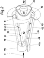
- FIGS. 2 and 3 are used simultaneously. Furthermore, in order not to make the individual figures unnecessarily confusing, partial aspects of this apparatus have been distributed to the individual figures, reference being made to them as necessary in the description of the exemplary embodiment.
- the core body of the apparatus 5 shown in FIG. 2 consists of two half hollow partial cone bodies 11, 12 which are offset from one another.
- the offset of the respective central axes creates a tangential air inlet slot 11c, 12c (FIG. 3) on both sides in an axially symmetrical arrangement, through which the above-mentioned pre-compressed air 16 flows into the interior 13 of the apparatus 5, ie into the cone cavity.
- the conical shape of the partial cone body 11 shown, 12 has a certain fixed angle in the direction of flow.
- the tangential width of the air inlet slots 11c, 12c is a measure that results from the displacement of the two central axes 11b, 12b (see FIG. 3) with respect to one another.
- the two partial cone bodies 11, 12 each have a cylindrical initial part 11a, 12a, which, analogous to the partial cone bodies 11, 12, are offset from one another, so that the tangential air inlet slots 11c, 12c are present over the entire length of the apparatus 5.
- the double cone apparatus 5 can be made purely conical, that is to say without a cylindrical initial part.
- a nozzle 14 is accommodated, which carries out a water injection into the interior 13 of the apparatus 5.
- the water injection ensures that the pre-compressed air 16, which flows via inlet channels 17a, 17b (see FIG. 3) through the tangential air inlet slots 11c, 12c into the interior 13 of the apparatus 5, is continuously subjected to a cooling process.
- the introduction of the required amount of water into the interior 13 of the burner can be done in a variety of ways.
- lines can be provided, which extend over the entire length of the double-cone apparatus 5 and have a number of openings on the long side through which the required water can be introduced. Due to the tangential inflow of air 16 in the The interior 13 of the apparatus 5 produces a swirl movement oriented in the axial direction, which by its nature is suitable for intimate mixing with the injected second medium, in our case it is a conical water spray pattern 15 that evaporates and so on cooling causes to accomplish. It should be noted that the vortex flow in the center itself is low in swirl, but it has an axial speed excess.
Landscapes
- Engineering & Computer Science (AREA)
- Chemical & Material Sciences (AREA)
- Combustion & Propulsion (AREA)
- Mechanical Engineering (AREA)
- General Engineering & Computer Science (AREA)
- Structures Of Non-Positive Displacement Pumps (AREA)
Priority Applications (3)
| Application Number | Priority Date | Filing Date | Title |
|---|---|---|---|
| EP92104491A EP0561011A1 (fr) | 1992-03-16 | 1992-03-16 | Compresseur avec refroidissement intermédiaire |
| CA 2091231 CA2091231A1 (fr) | 1992-03-16 | 1993-03-08 | Groupe compresseur |
| JP5055297A JPH0610702A (ja) | 1992-03-16 | 1993-03-16 | コンプレッサーグループ |
Applications Claiming Priority (1)
| Application Number | Priority Date | Filing Date | Title |
|---|---|---|---|
| EP92104491A EP0561011A1 (fr) | 1992-03-16 | 1992-03-16 | Compresseur avec refroidissement intermédiaire |
Publications (1)
| Publication Number | Publication Date |
|---|---|
| EP0561011A1 true EP0561011A1 (fr) | 1993-09-22 |
Family
ID=8209436
Family Applications (1)
| Application Number | Title | Priority Date | Filing Date |
|---|---|---|---|
| EP92104491A Withdrawn EP0561011A1 (fr) | 1992-03-16 | 1992-03-16 | Compresseur avec refroidissement intermédiaire |
Country Status (3)
| Country | Link |
|---|---|
| EP (1) | EP0561011A1 (fr) |
| JP (1) | JPH0610702A (fr) |
| CA (1) | CA2091231A1 (fr) |
Cited By (1)
| Publication number | Priority date | Publication date | Assignee | Title |
|---|---|---|---|---|
| WO2003102424A1 (fr) * | 2002-06-04 | 2003-12-11 | Alstom Technology Ltd | Procede pour faire fonctionner un compresseur |
Families Citing this family (6)
| Publication number | Priority date | Publication date | Assignee | Title |
|---|---|---|---|---|
| JP2877098B2 (ja) | 1995-12-28 | 1999-03-31 | 株式会社日立製作所 | ガスタービン,コンバインドサイクルプラント及び圧縮機 |
| SG104914A1 (en) | 1997-06-30 | 2004-07-30 | Hitachi Ltd | Gas turbine |
| USRE39092E1 (en) * | 1997-06-30 | 2006-05-09 | Hitachi, Ltd. | Gas turbine with water injection |
| USRE38831E1 (en) | 1997-06-30 | 2005-10-18 | Hitachi, Ltd. | Gas turbine having water spray injection control |
| US20130139517A1 (en) | 2010-08-27 | 2013-06-06 | Hitachi, Ltd. | Solar Assisted Gas Turbine System |
| EP2818665A4 (fr) | 2012-02-24 | 2016-03-23 | Mitsubishi Hitachi Power Sys | Système de turbine à gaz assisté par la chaleur solaire |
Citations (4)
| Publication number | Priority date | Publication date | Assignee | Title |
|---|---|---|---|---|
| FR995131A (fr) * | 1949-07-22 | 1951-11-28 | Rateau Soc | Perfectionnement aux turbo-réacteurs à deux flux |
| FR2264973A1 (fr) * | 1974-03-20 | 1975-10-17 | Mtu Muenchen Gmbh | |
| DE2925091A1 (de) * | 1979-06-21 | 1981-01-08 | Vinko Dipl Ing Mucic | Verbrennungskraftmaschine |
| EP0321809B1 (fr) * | 1987-12-21 | 1991-05-15 | BBC Brown Boveri AG | Procédé pour la combustion de combustible liquide dans un brûleur |
-
1992
- 1992-03-16 EP EP92104491A patent/EP0561011A1/fr not_active Withdrawn
-
1993
- 1993-03-08 CA CA 2091231 patent/CA2091231A1/fr not_active Abandoned
- 1993-03-16 JP JP5055297A patent/JPH0610702A/ja active Pending
Patent Citations (4)
| Publication number | Priority date | Publication date | Assignee | Title |
|---|---|---|---|---|
| FR995131A (fr) * | 1949-07-22 | 1951-11-28 | Rateau Soc | Perfectionnement aux turbo-réacteurs à deux flux |
| FR2264973A1 (fr) * | 1974-03-20 | 1975-10-17 | Mtu Muenchen Gmbh | |
| DE2925091A1 (de) * | 1979-06-21 | 1981-01-08 | Vinko Dipl Ing Mucic | Verbrennungskraftmaschine |
| EP0321809B1 (fr) * | 1987-12-21 | 1991-05-15 | BBC Brown Boveri AG | Procédé pour la combustion de combustible liquide dans un brûleur |
Cited By (2)
| Publication number | Priority date | Publication date | Assignee | Title |
|---|---|---|---|---|
| WO2003102424A1 (fr) * | 2002-06-04 | 2003-12-11 | Alstom Technology Ltd | Procede pour faire fonctionner un compresseur |
| US7093450B2 (en) | 2002-06-04 | 2006-08-22 | Alstom Technology Ltd | Method for operating a compressor |
Also Published As
| Publication number | Publication date |
|---|---|
| CA2091231A1 (fr) | 1993-09-17 |
| JPH0610702A (ja) | 1994-01-18 |
Similar Documents
| Publication | Publication Date | Title |
|---|---|---|
| DE3878902T2 (de) | Ringfoermige verbrennungseinheit mit tangentialem kuehllufteinspritzen. | |
| EP0681099B1 (fr) | Centrale à turbine à gaz | |
| DE3889539T2 (de) | Gasturbinenbrennkammer mit tangentialer brennstoffeinspritzung und zusätzlichen treibstrahlen. | |
| DE69412484T2 (de) | Verbrennungskammer eines gasturbinenmotors | |
| EP0542044B1 (fr) | Système de chambre de combustion annulaire | |
| EP0571782B1 (fr) | Procédé de fonctionnement d'une chambre de combustion pour turbine à gaz | |
| EP0433790B1 (fr) | Brûleur | |
| EP0718561B1 (fr) | Brûleur | |
| DE2628300C3 (de) | Gasturbinenanlage für Kraftfahrzeuge, wie Ackerschlepper; | |
| DE2143012A1 (de) | Brennersysteme | |
| EP0489193B1 (fr) | Chambre de combustion pour turbine à gaz | |
| DE4426351A1 (de) | Brennkammer | |
| DE2252733B2 (de) | Geschlossene gasgekühlte elektrische Maschine | |
| EP0636764A1 (fr) | Turbine à gaz avec refroidissement du rotor | |
| EP0487002A2 (fr) | Dispositif de climatisation de l'habitacle d'un véhicule automobile | |
| CH705324A1 (de) | Axialverdichter mit einer Einspritzvorrichtung zum Eindüsen einer Flüssigkeit. | |
| DE2158215C3 (de) | Brennkammer für Gasturbinentriebwerke | |
| DE1300735B (de) | Gasturbinentriebwerk | |
| DE2116429A1 (de) | Brennkammer fur Gasturbinenmaschinen | |
| EP0394800A1 (fr) | Brûleur à mélange préalable pour la génération de gaz chaud | |
| DE69502984T2 (de) | Gasturbinenbrennkammer | |
| DE3248439A1 (de) | Gasturbinentriebwerk mit gekuehlten schaufelspitzen | |
| EP1590603B1 (fr) | Refroidisseur a air pour centrales electriques et application d'un refroidisseur a air de ce type | |
| EP0474893A1 (fr) | Système de turbine à gaz | |
| DE102016112453A1 (de) | Getriebeturbomaschine |
Legal Events
| Date | Code | Title | Description |
|---|---|---|---|
| PUAI | Public reference made under article 153(3) epc to a published international application that has entered the european phase |
Free format text: ORIGINAL CODE: 0009012 |
|
| AK | Designated contracting states |
Kind code of ref document: A1 Designated state(s): AT BE CH DE DK ES FR GB GR IT LI LU MC NL PT SE |
|
| STAA | Information on the status of an ep patent application or granted ep patent |
Free format text: STATUS: THE APPLICATION IS DEEMED TO BE WITHDRAWN |
|
| 18D | Application deemed to be withdrawn |
Effective date: 19940323 |