EP0561041A2 - Dispositif de montage d'un boîtier de support magnétique dans un dispositif de reproduction de données - Google Patents
Dispositif de montage d'un boîtier de support magnétique dans un dispositif de reproduction de données Download PDFInfo
- Publication number
- EP0561041A2 EP0561041A2 EP92117844A EP92117844A EP0561041A2 EP 0561041 A2 EP0561041 A2 EP 0561041A2 EP 92117844 A EP92117844 A EP 92117844A EP 92117844 A EP92117844 A EP 92117844A EP 0561041 A2 EP0561041 A2 EP 0561041A2
- Authority
- EP
- European Patent Office
- Prior art keywords
- flap
- inlet
- holder
- container
- cartridge
- Prior art date
- Legal status (The legal status is an assumption and is not a legal conclusion. Google has not performed a legal analysis and makes no representation as to the accuracy of the status listed.)
- Withdrawn
Links
Images




Classifications
-
- G—PHYSICS
- G11—INFORMATION STORAGE
- G11B—INFORMATION STORAGE BASED ON RELATIVE MOVEMENT BETWEEN RECORD CARRIER AND TRANSDUCER
- G11B33/00—Constructional parts, details or accessories not provided for in the other groups of this subclass
- G11B33/02—Cabinets; Cases; Stands; Disposition of apparatus therein or thereon
- G11B33/027—Covers
-
- G—PHYSICS
- G11—INFORMATION STORAGE
- G11B—INFORMATION STORAGE BASED ON RELATIVE MOVEMENT BETWEEN RECORD CARRIER AND TRANSDUCER
- G11B15/00—Driving, starting or stopping record carriers of filamentary or web form; Driving both such record carriers and heads; Guiding such record carriers or containers therefor; Control thereof; Control of operating function
- G11B15/675—Guiding containers, e.g. loading, ejecting cassettes
- G11B15/67544—Guiding containers, e.g. loading, ejecting cassettes with movement of the cassette parallel to its main side and subsequent movement perpendicular thereto, i.e. front loading
- G11B15/67555—Guiding containers, e.g. loading, ejecting cassettes with movement of the cassette parallel to its main side and subsequent movement perpendicular thereto, i.e. front loading the second movement only being made by the cassette holder
-
- G—PHYSICS
- G11—INFORMATION STORAGE
- G11B—INFORMATION STORAGE BASED ON RELATIVE MOVEMENT BETWEEN RECORD CARRIER AND TRANSDUCER
- G11B17/00—Guiding record carriers not specifically of filamentary or web form, or of supports therefor
- G11B17/02—Details
- G11B17/04—Feeding or guiding single record carrier to or from transducer unit
- G11B17/0401—Details
- G11B17/0405—Closing mechanism, e.g. door
Definitions
- the present invention relates to a mounting device of a container device such as a cartridge and a cassette in an information reproducing device, and more particularly to a mounting structure of a flap for an inlet of such a reproducing device.
- an inlet for loading or ejecting the cartridge or the cassette into or from the device is provided with a flap for closing the inlet, thereby preventing foreign material such as dust from entering into the device so as to protect the recording medium and an information reproducing mechanism in the device.
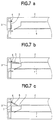
- Figs. 6a to 7c show a main part of an information reproducing device having a conventional structure of a flap.
- the device comprises a casing 2, an inlet 3 provided in a front panel of the casing 2, and a flap 5 for closing the inlet 3.
- the flap 5 is pivotally mounted on a pivot pin 6 secured to the inside of the casing 2 near the upper peripheral portion of the inlet 3 and urged by an elastic means such as a spring (not shown) to close the inlet 3.
- a cartridge holder 4 is provided in the casing 2 such that an opening thereof corresponds to the inlet 3. When a cartridge 1 such as a tape cartridge is inserted into the inlet 3, the holder 4 holds the cartridge 1 to load it on an information reproducing mechanism in the device.
- the flap 5 closes the inlet 3 as shown in Figs. 6a and 7a, thereby preventing dust from entering into the casing 2.
- the holder 4 is moved downwardly by a loading device (not shown) to the reproducing mechanism (not shown) as shown in Fig. 7c.
- the flap 5 is rotated downwardly by the elastic means, keeping the engagement state with the upper surface of the cartridge 1.
- the flap 5 does not completely close the inlet 3 so that the cartridge 1 can easily be ejected from the inlet 3.
- a space 7 is formed inside the inlet 3, and the inlet 3 is not completely closed.
- Figs. 8a to 9c show another conventional structure of a flap.
- the inlet 3 of the casing 2 is provided with a pair of flaps, namely an upper flap 5a and a lower flap 5b.
- the upper flap 5a is pivotally mounted on a pivot pin 6a secured to an upper peripheral portion of the inlet 3 at the inside of the casing 2.
- the lower flap 5b is pivotally mounted on a pivot pin 6b secured to a lower peripheral portion of the inlet 3 corresponding to the upper flap 5a.
- the upper and lower flaps 5a and 5b are urged by respective elastic means (not shown) toward the inlet 3 so that the lower periphery of the upper flap 5a is engaged with the upper periphery of the lower flap 5b to close the inlet 3.
- Figs. 8a and 9a show a situation where the inlet 3 is closed by the flaps 5a and 5b.
- An object of the present invention is to provide a mounting structure of a cartridge for an information reproducing device which prevents dust from entering into the device during the playback operation and has a simple construction without increasing the size of the device.
- a mounting device of a container of a recording medium in an information reproducing device having a casing with an inlet for the container, comprising a holder for holding the container, the holder being located inside the inlet and provided to be moved downwardly, a lowering mechanism for lowering the holder, and a flap pivotally mounted on the holder at a front portion thereof.
- the flap comprises a first flap provided for closing the inlet in an inoperative state and to be opened by the container which is inserted into the casing, and a second flap provided to be pivoted together with the first flap and to close at least a part of the inlet when the holder is lowered.
- the lowering mechanism comprises a slide frame provided to be slid by the inserted container, and cam grooves for lowering the holder.
- the flap is mounted on the holder so that the rotating operation of the flap does not interfere with the vertical movement of the holder.
- the device is simplified in construction.
- the device comprises a casing 10, an inlet 11, and a flap 12 for closing the inlet 11.
- a cartridge holder 13 is provided in the casing 10 corresponding to the inlet 11.
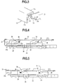
- the cartridge holder 13 is vertically slidably mounted on opposite pins 20 secured to a frame 21 of the casing 10.
- the holder 13 has a pair of supporting portions 13a at the front end thereof, projected from the opposite side plates thereof toward the inlet 11. As shown in Fig. 3, the supporting portions 13a have pivot pins 14 on which the flap 12 is pivotally mounted.
- the flap 12 has an L-shaped section comprising a first flap 12a and a second flap 12b integrated with the first flap 12a and provided perpendicular to the first flap 12a.
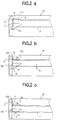
- the flap 12 is urged or biassed by a spring 22 in the clockwise direction in Fig. 2a about the pins 14 toward the inlet 11 .
- a slide frame 23 is slidably mounted on the frame 21.
- the slide frame 23 has a pair of cam grooves 24 at each side thereof.
- the cam grooves 24 slidably engage with pins 25 mounted on the cartridge holder 13.
- the casing 10 is provided with a projection 15 on a lower portion of the inlet 11 for regulating a lowering movement of the holder 13.
- FIGs. 1a and 2a show a situation of the flap 12 where no recording medium is mounted in the casing 10.
- a cartridge 16 is inserted into the inlet 11 as shown in Fig. 1b, the first flap 12a is pushed inwardly so as to be rotated about the pins 14 in the counter-clockwise direction in Fig. 2b.
- the cartridge 16 is inserted into the cartridge holder 13, while the first flap 12a is rotated to the position perpendicular to the inlet 11 in accordance with the upper surface 16a of the cartridge 16.
- the flap 12 is lowered together with the holder 13, while the first flap 12a is abutted against the upper surface 16a of the cartridge 16 by the spring 22, and the second flap 12b engages with the inside wall of the casing 10 on an upper portion of the inlet 11. In this state, since the flap 12a engages with the upper surface 16a of the cartridge 16 and a rear end portion 16b of the cartridge 16 closes the inlet 11, any dust is prevented from entering into the casing 10.
- an underside 16c of the cartridge 16 engages with the projection 15. During reproducing information recorded on the recording medium, any dust is prevented from entering into the device.
- first flap 12a and the second flap 12b may be formed separately as far as these flaps 12a, 12b are adapted to be rotated together.
- the inlet 11 may be closed only by the second flap 12b. In that case, the projection 15 is positioned so as to locate the cartridge 16 lower than the inlet 11.
- a flap for the inlet of the casing comprises a first flap and a second flap and is pivotally mounted on the holder of the cartridge. During reproducing any information, the inlet is closed completely by the second flap and the cartridge without increasing the size of the device, thereby preventing any dust from entering into the device. Since the flap is operated with the movement of the cartridge, it is not necessary to provide a driving mechanism for opening the flap.
Landscapes
- Feeding And Guiding Record Carriers (AREA)
Applications Claiming Priority (2)
| Application Number | Priority Date | Filing Date | Title |
|---|---|---|---|
| JP93490/92 | 1992-03-19 | ||
| JP4093490A JPH05266555A (ja) | 1992-03-19 | 1992-03-19 | 情報記録再生装置 |
Publications (2)
| Publication Number | Publication Date |
|---|---|
| EP0561041A2 true EP0561041A2 (fr) | 1993-09-22 |
| EP0561041A3 EP0561041A3 (fr) | 1994-10-12 |
Family
ID=14083788
Family Applications (1)
| Application Number | Title | Priority Date | Filing Date |
|---|---|---|---|
| EP19920117844 Withdrawn EP0561041A3 (fr) | 1992-03-19 | 1992-10-19 | Dispositif de montage d'un boîtier de support magnétique dans un dispositif de reproduction de données. |
Country Status (2)
| Country | Link |
|---|---|
| EP (1) | EP0561041A3 (fr) |
| JP (1) | JPH05266555A (fr) |
Cited By (1)
| Publication number | Priority date | Publication date | Assignee | Title |
|---|---|---|---|---|
| DE19542976A1 (de) * | 1994-11-17 | 1996-05-23 | Pinnacle Micro Inc | Verschlußeinrichtung für eine Datenaufzeichnungs-/Wiedergabeeinrichtung |
Families Citing this family (2)
| Publication number | Priority date | Publication date | Assignee | Title |
|---|---|---|---|---|
| JPH09106666A (ja) * | 1995-10-13 | 1997-04-22 | Kofu Nippon Denki Kk | フロッピィディスク駆動装置 |
| KR20050017661A (ko) | 2003-08-08 | 2005-02-22 | 삼성전자주식회사 | 디스크 드라이브의 도어장치 |
Family Cites Families (2)
| Publication number | Priority date | Publication date | Assignee | Title |
|---|---|---|---|---|
| JPS5619201Y2 (fr) * | 1974-02-20 | 1981-05-07 | ||
| US5086422A (en) * | 1989-06-19 | 1992-02-04 | Ricoh Company, Ltd. | Optical disk apparatus |
-
1992
- 1992-03-19 JP JP4093490A patent/JPH05266555A/ja active Pending
- 1992-10-19 EP EP19920117844 patent/EP0561041A3/fr not_active Withdrawn
Cited By (3)
| Publication number | Priority date | Publication date | Assignee | Title |
|---|---|---|---|---|
| DE19542976A1 (de) * | 1994-11-17 | 1996-05-23 | Pinnacle Micro Inc | Verschlußeinrichtung für eine Datenaufzeichnungs-/Wiedergabeeinrichtung |
| FR2727237A1 (fr) * | 1994-11-17 | 1996-05-24 | Pinnacle Micro Inc | Mecanisme obturateur pour obturer l'ouverture d'un module d'entrainement |
| NL1001690C2 (nl) * | 1994-11-17 | 1997-06-10 | Asahi Optical Co Ltd | Een afdekmechanisme voor het afdekken van de opening van een aandrijfeenheid. |
Also Published As
| Publication number | Publication date |
|---|---|
| JPH05266555A (ja) | 1993-10-15 |
| EP0561041A3 (fr) | 1994-10-12 |
Similar Documents
| Publication | Publication Date | Title |
|---|---|---|
| US5150269A (en) | Disk cartridge with write protect mechanism | |
| US6324147B2 (en) | Electronic equipment | |
| US6404720B1 (en) | Disk drive | |
| JPH06282977A (ja) | 情報記録再生装置 | |
| US4833553A (en) | Magnetic disc cartridge loading and unloading mechanism | |
| US5481520A (en) | Disk player door assembly | |
| US5222005A (en) | Loading unit for case which houses recording disk | |
| US5883871A (en) | Information recording/reproduction apparatus with shutter opening/closing mechanism on upper surface of cartridge holder | |
| KR19990037517A (ko) | 기록 매체 카트리지 장착 장치 | |
| JPH10199084A (ja) | ディスクドライブ装置 | |
| EP0411670A2 (fr) | Cartouche à disque | |
| US6463027B1 (en) | Disc case | |
| JP3296375B2 (ja) | ディスクカートリッジ装置 | |
| JP4301109B2 (ja) | 光ディスク装置の防塵機構 | |
| JP4264402B2 (ja) | 記録媒体装着装置 | |
| JP3024481B2 (ja) | ディスク装置 | |
| JP3796603B2 (ja) | 情報ディスク装置 | |
| JP3829222B2 (ja) | カートリッジおよび情報ディスク装置 | |
| US6233220B1 (en) | Disc cartridge having variable gap | |
| JP3829154B2 (ja) | 情報ディスク装置 | |
| JPH04349266A (ja) | ディスク装置及びディスクカートリッジの保存ケース | |
| JPH052801A (ja) | 磁気記録再生装置のカセツト着脱装置 | |
| JPH076472A (ja) | 情報記録媒体のドライブ装置 | |
| JPH04276352A (ja) | 記録媒体着脱装置 | |
| US20060085811A1 (en) | Disk cartridge |
Legal Events
| Date | Code | Title | Description |
|---|---|---|---|
| PUAI | Public reference made under article 153(3) epc to a published international application that has entered the european phase |
Free format text: ORIGINAL CODE: 0009012 |
|
| AK | Designated contracting states |
Kind code of ref document: A2 Designated state(s): DE FR GB NL |
|
| PUAL | Search report despatched |
Free format text: ORIGINAL CODE: 0009013 |
|
| AK | Designated contracting states |
Kind code of ref document: A3 Designated state(s): DE FR GB NL |
|
| STAA | Information on the status of an ep patent application or granted ep patent |
Free format text: STATUS: THE APPLICATION IS DEEMED TO BE WITHDRAWN |
|
| 18D | Application deemed to be withdrawn |
Effective date: 19941101 |