EP0561299A1 - Procédé et dispositif de fermeture de bouteilles - Google Patents
Procédé et dispositif de fermeture de bouteilles Download PDFInfo
- Publication number
- EP0561299A1 EP0561299A1 EP93104065A EP93104065A EP0561299A1 EP 0561299 A1 EP0561299 A1 EP 0561299A1 EP 93104065 A EP93104065 A EP 93104065A EP 93104065 A EP93104065 A EP 93104065A EP 0561299 A1 EP0561299 A1 EP 0561299A1
- Authority
- EP
- European Patent Office
- Prior art keywords
- bottle
- closing
- holding element
- closing tool
- crown
- Prior art date
- Legal status (The legal status is an assumption and is not a legal conclusion. Google has not performed a legal analysis and makes no representation as to the accuracy of the status listed.)
- Granted
Links
Images

Classifications
-
- B—PERFORMING OPERATIONS; TRANSPORTING
- B67—OPENING, CLOSING OR CLEANING BOTTLES, JARS OR SIMILAR CONTAINERS; LIQUID HANDLING
- B67B—APPLYING CLOSURE MEMBERS TO BOTTLES JARS, OR SIMILAR CONTAINERS; OPENING CLOSED CONTAINERS
- B67B3/00—Closing bottles, jars or similar containers by applying caps
-
- B—PERFORMING OPERATIONS; TRANSPORTING
- B67—OPENING, CLOSING OR CLEANING BOTTLES, JARS OR SIMILAR CONTAINERS; LIQUID HANDLING
- B67B—APPLYING CLOSURE MEMBERS TO BOTTLES JARS, OR SIMILAR CONTAINERS; OPENING CLOSED CONTAINERS
- B67B3/00—Closing bottles, jars or similar containers by applying caps
- B67B3/02—Closing bottles, jars or similar containers by applying caps by applying flanged caps, e.g. crown caps, and securing by deformation of flanges
-
- B—PERFORMING OPERATIONS; TRANSPORTING
- B67—OPENING, CLOSING OR CLEANING BOTTLES, JARS OR SIMILAR CONTAINERS; LIQUID HANDLING
- B67B—APPLYING CLOSURE MEMBERS TO BOTTLES JARS, OR SIMILAR CONTAINERS; OPENING CLOSED CONTAINERS
- B67B3/00—Closing bottles, jars or similar containers by applying caps
- B67B3/02—Closing bottles, jars or similar containers by applying caps by applying flanged caps, e.g. crown caps, and securing by deformation of flanges
- B67B3/10—Capping heads for securing caps
- B67B3/12—Capping heads for securing caps characterised by being movable axially relative to cap to deform flanges thereof, e.g. to press projecting flange rims inwardly
-
- B—PERFORMING OPERATIONS; TRANSPORTING
- B67—OPENING, CLOSING OR CLEANING BOTTLES, JARS OR SIMILAR CONTAINERS; LIQUID HANDLING
- B67C—CLEANING, FILLING WITH LIQUIDS OR SEMILIQUIDS, OR EMPTYING, OF BOTTLES, JARS, CANS, CASKS, BARRELS, OR SIMILAR CONTAINERS, NOT OTHERWISE PROVIDED FOR; FUNNELS
- B67C7/00—Concurrent cleaning, filling, and closing of bottles; Processes or devices for at least two of these operations
- B67C7/0006—Conveying; Synchronising
- B67C7/002—General lay-out of bottle-handling machines
Definitions
- the invention relates to a method and a device for carrying out the method for closing bottles, in which a filled bottle is drawn off from a filling valve of a filler and sealed in a capper by fitting and flanging a crown cap.
- Such a method and a device for carrying out the method are known from DE 40 18 121. Accordingly, a plurality of bottles are filled in a rotary filler and crown corks are flanged at their crown edge by a closing cone in a downstream capper. During the flanging, the crown caps are pressed onto the bottle mouth by a hold-down device with an additional force of approximately 80 kp (head pressure). Between the capper and the rotary filler, a pre-capper is arranged, which is still in the rotary filler. H. after removing the bottle from the filling valve, it engages in the space formed between the bottle mouth and the filling valve and a crown cap is placed on the bottle mouth. The crown cork is then pressed onto the bottle mouth with a force of approximately 20 kp and the crown cork is attached to the bottle by deforming the edge of the crown in places.
- a disadvantage of the known method is that between the pre-closure and the final closure of the bottles they have to be transported from the rotary filler to the capper.
- the pre-closure of the crown cap largely prevents foam or liquid from escaping from the filler to the capper during this transfer time, degassing of the filled liquid or penetration of air cannot always be prevented. This deteriorates the shelf life or the quality of the filled product.
- Another disadvantage is that a relatively high head pressure is generated in the closer, which leads to an unfavorable deformation of the Sealing material can result in the crown cap. A damaged or even destroyed sealing material in turn leads to inadequate closure of the bottle, as a result of which liquid degassing or air entry is possible.
- the arrangement of the capper results in certain advantages due to the quick pre-closure of the bottles, but the construction is more complex and expensive due to the additional component. Accordingly, maintenance is becoming more extensive and complex.
- the invention is therefore based on the object of improving a method for closing bottles of the type mentioned at the outset with a view to simplifying and tightly closing the bottles in a shorter time.
- This object is achieved in a method with the features of the preamble of claim 1 in that for the immediate closure of the filled bottle, the crown cork held ready in the capper and a closing tool designed for flanging the crown cork are inserted in a positioning phase between the bottle mouth and the filling valve and then the crown cork is placed headless on the bottle mouth and the closure phase is initiated.
- the holding element and the closing tool can be inserted into the space formed between the bottle mouth and the filling valve. While the bottle is still in the filler, the crown cap held by the holding element can be placed on the bottle mouth. There is no additional application of force for pressing the crown cork onto the bottle mouth, so that the crown cork lies practically without head pressure on the bottle mouth. Immediately after the positioning phase, the edge of the crown is fastened to the bottle in an unsealed and sealed manner using the sealing tool. Even with a high bottle throughput, the bottles are completely closed shortly after exiting the filler and can for further processing, e.g. B. for labeling.
- the bottles are closed without a head pressure, both a lower overall height of the capper due to the lack of force application devices is possible and a disadvantageous deformation of the sealing material in the crown cap is prevented. Because the bottles are no longer required to be pre-closed, the construction of the system for filling and closing bottles is simplified and is more cost-effective. At the same time, the bottles are completely closed in a considerably shorter time and with a significantly lower pressure load on the bottles.
- the closing tool for flanging the crown cork is lowered in the direction of the bottle mouth and then raised to release the closed bottle.
- the capping tool is movably mounted on the capper for height adjustment between the holding element and the bottle mouth. The simple up and down movement enables the crown cap to be deformed quickly and precisely.
- the closing tool flanges an edge of the crown cap through a closing cone.
- the closing cone is positioned in the space formed between the bottle mouth and the filling valve directly above the bottle mouth.
- the closing tool moves up and down, the closing cone with its conical surfaces flaps the edge of the crown and can be easily removed from the bottle mouth after the crown cap has been deformed. The bottle is then completely closed and can be removed.
- the capper is designed as a rotary capper is, filler and capper are partially overlapping.
- the filler is designed as a so-called rotary filler. Filler and capper overlap in a peripheral area, with crown caps and capping tools being positioned above the bottle mouth in this area.
- the closing tool In order to enable the closing tool to move up and down in a simple manner, it is lowered and raised by means of a cam roller guided in a guide curve.
- the cam roller is rotatably mounted on the capping tool and is guided in the guide cam arranged stationary to the capper.
- the bottles in the filler stand up on a lifting plate and are gripped by the capper with a holding arm on the bottle neck.
- the holding arm has an essentially U-shaped receiving opening facing the bottle, into which the bottle is inserted in the overlap area of the filler and the capper.
- the bottle is pulled off the lifting plate by the holding arm after the positioning phase.
- the deformation phase is carried out by the interaction of the holding arm and the closing tool, without plates supporting the bottom of the bottle.
- the holding element can be arranged fixed above the closing cone, while in another embodiment the holding element is movably mounted in the closing cone and, after positioning the crown cork on the bottle mouth, is pushed out of the closing cone so that it can act as an ejector .
- the holding element is also intended to serve as an ejector, it is positioned directly above the crown cap when the closing tool is lifted and remains in this position until the closing tool or the closing cone of the closing tool has added the bottle mouth or the crown cap. In order to achieve this, it is advantageous if the holding element acting as an ejector is controlled in height independently of the closing tool.
- At least the following method steps are carried out: Lowering the closing tool, Lowering the holding element from a starting position to just above or up to the non-head contact on the crown cap, Lifting the closing tool after flanging while holding the holding element in the position assumed in the lowering step of the holding element until the crown cap is out of contact with the closing cone of the closing tool and lifting the holding element and the closing tool into the starting position.
- the holding element When the holding element is positioned in the lowered position, it is not necessary for the holding element to come into direct contact with the crown cap, rather it is sufficient if it is positioned directly above the crown cap.
- the possible height shift between the holding element and the closing tool is chosen at least so large that the holding element can safely push the crown cork or the bottle mouth closed with the crown cork out of the closing cone of the closing tool.
- the height adjustment of the holding element is advantageously carried out just like the height adjustment of the closing tool by means of a cam roller guided in a guide curve.
- a holding arm can be assigned to a closing tool.
- the capper can have a base plate which has receptacles associated with a capping tool along its circumference. The bottles with their bottlenecks can be inserted into them.
- a cover plate is arranged opposite the base plate, which closes the capper at the top. Both the bottom plate and the cover plate have essentially the same diameter.
- the reference numeral 1 denotes a filler, which is designed as a rotary filler in the present embodiment.
- a plurality of lifting and lowering lifting plates 13, on which bottles 2 can be placed, are arranged at regular intervals over a circumference of the rotary filler.
- Filling valves (not shown in FIG. 1) with associated centering bells are arranged above the bottle mouths.
- the filler 1 is charged with empty bottles 2 via a feed belt 30 and an inlet star 31.
- the bottles 2 are filled.
- a rotary capper 5 partially overlaps the rotary filler 1.
- the bottles 2 are closed and after the closure process has been completed, the bottles 2 can be transported further to a discharge belt 32, which transports the bottles to further processing stations, not shown, such as, for. B. transported away a labeler.
- the lifting plates 13 arranged between the rotary sealer 5 and the inlet star 31 are empty and can only be loaded with empty bottles 2 through the inlet star 31.
- the rotary sealer 5 rotates about its axis of rotation 18 in the direction of rotation 16.
- the directions of rotation 15 and 16 of the rotary filler 1 and the rotary sealer 5 are directed in opposite directions, the rotary filler 1 being able to rotate clockwise and the rotary sealer 5 being counterclockwise.
- a crown cork feeder 33 To supply the rotary sealer 5 with crown corks, not shown, it is connected at one point on its circumference to a crown cork feeder 33. This leads synchronized to the rotary sealer 5 from a crown cork storage container 36 via a drop channel 37 to the rotary sealer 5.
- the bottle 2 is closed in the rotary sealer 5 in the embodiment shown in FIG. 1 between the section line AB and the discharge belt 32.
- the rotary capper 5 has a smaller radius 23 than the rotary filler 1.
- a bottle 2 is placed on a lifting plate 13.
- a filling valve 3 with a centering bell 38 is arranged at a distance from the bottle 2 above the filled bottle.
- the lifting plate 13 can be lowered or raised in the direction 40.
- the filling valve 3 is connected to a liquid container 39 of the rotary filler 1.
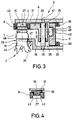
- Part of the rotary sealer 5 is inserted between the centering bell 38 and the bottle 2. Between a holding arm 14 or base plate 22 and a cover plate 21, a closing tool 6 is mounted on a guide pin 24 so that it can be adjusted in height.
- the closing tool 6 is shown in detail below.
- the closing tool 6 is mounted in a height-adjustable manner in the direction 8 on a guide pin 24. This is fixed with its ends 45 in the cover plate 21 and the base plate 22.
- the top and bottom plates 21 and 22 are arranged parallel to one another, the bottom plate 22 being offset in its holding end assigned to the bottle 2 by a step-like height jump 26 in the direction of the top plate 21.
- the holding end 47 has a receiving opening 20 for receiving a bottle neck 19. To hold the bottle 2, it rests with a thickened bottle collar 48 arranged below the bottle mouth 7 on the holding end 47 surrounding the receiving opening 20.
- the receiving opening 20 is substantially U-shaped in plan view and adapted to the diameter of the bottle neck 19 below the bottle collar 48.
- the closing tool 6 is essentially L-shaped, an L-leg being designed as a guide sleeve 25. This runs concentrically to the longitudinal axis 41 of the guide bolt 24. To adjust the height of the guide bushing 25, it points to that of the bottle 2 opposite side on a cam roller 12, the axis of rotation 42 is substantially perpendicular to the longitudinal axis 41 of the guide pin.
- the cam roller 12 is inserted in a self-contained guide groove 49 of a stationary guide curve 11. By moving the cam roller 12 along the guide groove 49, the height of the closing tool 6 is adjusted in the direction 8.
- the guide curve 11 is fixed in relation to the rotary closer 5. Upon rotation of the rotary capper 5 in the direction 16 acc. 1, cover plate 21 and base plate 22 rotate along the guide curve 11 via ball bearings 29 arranged between them.
- the guide curve 11 is essentially arranged concentrically to the axis of rotation 18 of the rotary sealer from FIG. 1.
- the other L-leg of the closing tool 6 is arranged between the cover plate 21 and the bottle mouth 7.
- This has a closing cone 9 at its end associated with the bottle mouth 7.
- the closure cone 9 has an essentially cylindrical bore which has conically widened surfaces 43 at its end facing the bottle mouth 7.
- a crown cap 4 is held in the area of these surfaces. This ends flush with the sealing cone in the direction of bottle 2.
- a holding element 10 is fastened to the cover plate 21 in order to hold the crown cork in the closing cone 9. This has an outer diameter corresponding to the inner diameter of the cylindrical bore of the closing cone.
- a magnet 27 is embedded flush in the holding element 10.
- Crown cork 4, holding element 10, closing cone 9 and bottle mouth 7 are arranged concentrically with the longitudinal axis 44 of the bottle.
- FIG. 4 shows a further embodiment of a holding element 10.
- all the other components of the capper 5 and the bottle 2 have been omitted apart from the cover plate 21 and the sealing cone 9.
- the holding element 10 is inserted into the cylindrical bore of the closing cone 9. Between the cover plate 21 and the sealing cone 9, the holding element 10 is formed with an edge flange 46 resting on the sealing cone 9. To hold a crown cap (not shown), a magnet 27 is countersunk in the holding element 10, flush with the edge flange 46, in the holding element 10. The holding element 10 extends essentially between the cover plate 21 and the cone surfaces 43. When the closing cone 9 is lowered, the loosely lying holding element 10 can be lowered until the crown cap rests on the bottle mouth. When the closing cone 9 is lowered further, the holding element 10 can be pushed out of the cylindrical bore.
- the bottles 2 introduced into the overlap area of the rotary filler 1 and the capper 5 are already filled, the bottles being pulled off the associated filling valves 3 by lowering the lifting plate 13 accordingly.
- the capper 5 is inserted into the free space formed between the bottle mouth and the filling valve, in particular the holding element holding the crown cap and the sealing cone of the closing tool being positioned between the filling valve and the bottle mouth.
- the positioning phase for positioning a crown cork above the bottle mouth is completed with the bottle, which is arranged on the line A-B from FIG. 1.
- the bottle neck 10 has completely run into the receiving opening 20 here.
- Fig. 2 the crown cork is correctly positioned relative to the bottle mouth and is then lowered onto the bottle mouth.
- the crown cork 4 is placed on the bottle mouth 7 by lowering the closing cone 9, held by the magnet 27, and crimped on further lowering. After completing the deformation the crown cap is sealingly attached to the bottle mouth 7. The closing cone is then raised to the position shown in FIG. 3 and the closed bottles are transferred from the rotary sealer 5 to the discharge belt 32. To supply a new crown cork, a new crown cork is fed to the holding element 10 by the crown cork feeder 33 when the rotary sealer 5 rotates in the direction 16.
- the crown cap 4 lies in the embodiment of the holding element according to FIG. 3 as well as in the embodiment according to FIG. 4 essentially without applying force to the bottle mouth 7, the bottles are closed without a head pressure. Only the forces that occur during the deformation of the crown edge act on the bottle mouth and thus on the bottle. Due to the low overall height of the holding element and the sealing cone and the head cap without pressure on the bottle mouth, the crown cap can be deformed to close the bottle immediately after the bottle is removed from the filling valve and at least partially in the filler.
- the closing force generated by the sealing cone 9 during the flanging of the crown cap 4 is introduced directly into the holding end 47 via the thickened bottle collar 48, so that the bottle body remains unloaded.
- the receiving opening 20 is provided with an exchangeable insert 35 made of hard-elastic material, which is essentially U-shaped in plan view.
- the height of the bottle neck 19 in the receiving opening 20 also provides the counterforce necessary to pull off the closure cone 9 after the crown cap 4 has been deformed, the holding element 10 acting as an ejector if the bottle 2 is lifted too much.
- the holder of the bottle 2 in the receiving opening 20 in the radial direction can, for. B. by clamping or by a recess for the bottle collar 48.
- FIGS. 1 and 2. Another possibility is shown in FIGS. 1 and 2.
- the bracket is carried out at a height of the holding end 47 between the cutting line AB and the discharge belt 32, the guide bend 28 arranged in a stationary manner.
- the closed bottles 2 are led out of the receiving openings 20 through a likewise stationary guide rail 34.
- the guide rail 34 begins below the base plate 22 in the area of the discharge belt 32.
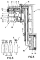
- the holding element 10 is arranged on the cover plate 21, as in the exemplary embodiment according to FIG. 3, but the cover plate, together with the holding element, can be opened via its own cam guide 50 independently of the closing tool 6, which is also controlled in terms of height - and be moved.
- Both the closing tool 6 and the cover plate 21 are guided on the guide pin 24, which can be designed to be secured against rotation, and through openings 51 and 52 in the holding arm 14 and a collar 53 running around the rotor.
- the control cam block 54 in which the control cam 50 for the holding element 10 and also the control cam for the closing tool 6 run, is arranged in a stationary manner on the rotor via bearings 55.
- the closing process can be carried out, as shown in FIG. 6 in steps a to d.
- both the closing tool 6 and the cover plate 21 with the holding element 10 are in a position raised above the bottle in the starting point such that the crown cap can be positioned under the holding element 10.
- the holding element is lowered together with the closing tool, the holding element being stopped in a position in which it lies more or less loosely, ie without exerting a head pressure, on the crown cap or just above the crown cap loosely seated on the mouth is positioned.
- the closing tool is moved into the closing position shown in step b, in which the edge of the crown cap is flanged.
- step c the closing tool is then raised again, so that the crown cap is released from the closing cone.
- the holding element retains the position assumed in step b. The holding element therefore acts when Lifting the capping tool 6 as an ejector and ensures that the bottles reliably come out of the capping cone.
- step d the closing tool and the holding element are then brought back into the raised starting position.
Landscapes
- Engineering & Computer Science (AREA)
- Mechanical Engineering (AREA)
- Sealing Of Jars (AREA)
- Filling Of Jars Or Cans And Processes For Cleaning And Sealing Jars (AREA)
- Supplying Of Containers To The Packaging Station (AREA)
- Separation, Recovery Or Treatment Of Waste Materials Containing Plastics (AREA)
- Containers Having Bodies Formed In One Piece (AREA)
- Closing Of Containers (AREA)
Applications Claiming Priority (2)
| Application Number | Priority Date | Filing Date | Title |
|---|---|---|---|
| DE4208441 | 1992-03-17 | ||
| DE4208441A DE4208441A1 (de) | 1992-03-17 | 1992-03-17 | Verfahren und vorrichtung zum verschliessen von flaschen |
Publications (2)
| Publication Number | Publication Date |
|---|---|
| EP0561299A1 true EP0561299A1 (fr) | 1993-09-22 |
| EP0561299B1 EP0561299B1 (fr) | 1995-03-01 |
Family
ID=6454229
Family Applications (1)
| Application Number | Title | Priority Date | Filing Date |
|---|---|---|---|
| EP93104065A Expired - Lifetime EP0561299B1 (fr) | 1992-03-17 | 1993-03-12 | Procédé et dispositif de fermeture de bouteilles |
Country Status (10)
| Country | Link |
|---|---|
| US (1) | US5402623A (fr) |
| EP (1) | EP0561299B1 (fr) |
| JP (1) | JPH06100084A (fr) |
| KR (1) | KR930019547A (fr) |
| CN (1) | CN1083446A (fr) |
| AT (1) | ATE119133T1 (fr) |
| BR (1) | BR9301205A (fr) |
| CA (1) | CA2091720A1 (fr) |
| DE (2) | DE4208441A1 (fr) |
| ES (1) | ES2070015T3 (fr) |
Cited By (4)
| Publication number | Priority date | Publication date | Assignee | Title |
|---|---|---|---|---|
| WO1997043188A1 (fr) * | 1996-05-09 | 1997-11-20 | Crown Cork Ag | Bouchon de recipient et embouchure de recipient |
| DE19728059A1 (de) * | 1997-07-01 | 1999-01-07 | Max Kettner Gmbh & Co Kg I K | Verschraubvorrichtung für Getränkeflaschen |
| WO2007138627A1 (fr) * | 2006-06-01 | 2007-12-06 | Mecc-Lan S.R.L. | Couvercle de fermeture pour un élément de radiateur, élément de radiateur, mécanisme d'assemblage d'un couvercle sur un élément de radiateur et méthode d'assemblage associée |
| US8935905B2 (en) | 2007-05-30 | 2015-01-20 | Khs Gmbh | Method and apparatus for the manufacture of disposable, one-way, single-use beverage containers such as kegs |
Families Citing this family (20)
| Publication number | Priority date | Publication date | Assignee | Title |
|---|---|---|---|---|
| IT1264301B1 (it) * | 1993-12-24 | 1996-09-23 | Ima Spa | Macchina automatica ad elevata produzione, per il riempimento e la chiusura di flaconi od altri contenitori. |
| AU2001268111A1 (en) * | 2000-05-31 | 2001-12-11 | Fogg Filler Company | Filler device sub-assembly and associated method |
| DE10130533A1 (de) * | 2001-06-25 | 2003-01-09 | Pactec Verpackungsmaschinen Fa | Verfahren und Vorrichtung zur Montage und Verpackung kleinstückiger Artikel |
| US6889482B2 (en) | 2002-10-10 | 2005-05-10 | Fogg Filler Company | Filler device sub-assembly |
| DE102007028429A1 (de) * | 2007-06-20 | 2008-12-24 | Krones Ag | Vorrichtung zum Verschließen von Behältern mit Schraubverschlüssen |
| EP2096079A1 (fr) * | 2008-02-08 | 2009-09-02 | F.Hoffmann-La Roche Ag | Dispositif de sertissage pour bouchons de récipient |
| DE102009003025A1 (de) * | 2009-05-12 | 2010-11-18 | Ball Packaging Europe Gmbh | Verfahren zum Befüllen von Lebenmittelbehältern |
| CN102574670B (zh) * | 2009-06-26 | 2014-06-25 | 西得乐独资股份公司 | 在机器上将液体装瓶的方法、将液体装瓶的机器及所得瓶 |
| KR100932172B1 (ko) * | 2009-07-17 | 2009-12-16 | 김시일 | 냉각장치가 구비된 금형코아 |
| DE102009040363A1 (de) * | 2009-09-07 | 2011-03-10 | Krones Ag | Vorrichtung und Verfahren zum Herstellen von Kunststoffflaschen |
| US20110113732A1 (en) * | 2009-11-13 | 2011-05-19 | The Coca-Cola Company | Method of isolating column loading and mitigating deformation of shaped metal vessels |
| DE102014106205A1 (de) * | 2014-05-05 | 2015-11-05 | Khs Gmbh | Verfahren zum Betrieb einer Verschließstation, Verschließstation sowie Abfüllanlage mit einer solchen Verschließstation |
| CN104058249B (zh) * | 2014-06-17 | 2016-09-28 | 广州丽盈塑料有限公司 | 一种自动定位上内塞机构 |
| US10017368B2 (en) * | 2014-11-25 | 2018-07-10 | The Wine Group, Inc. | Cap gripper |
| EP3292072B1 (fr) * | 2015-05-07 | 2022-05-25 | Tetra Laval Holdings & Finance S.A. | Procédé et appareil d'orientation de capuchon |
| CN108557733A (zh) * | 2018-05-09 | 2018-09-21 | 芜湖慧盈自动化设备有限公司 | 一种酒瓶用自动化压盖装置 |
| CN110775926B (zh) * | 2019-10-29 | 2022-03-08 | 江苏新美星包装机械股份有限公司 | 灌装封盖一体机 |
| DE102019135223A1 (de) * | 2019-12-19 | 2021-06-24 | Krones Ag | Verfahren und Vorrichtung zum Erkennen der Strukturintegrität eines zu verschließenden Behälters |
| CN111170241B (zh) * | 2019-12-20 | 2025-12-23 | 广州达意隆包装机械股份有限公司 | 瓶盖对中装置及旋盖机 |
| DE102023107926A1 (de) | 2023-03-29 | 2024-10-02 | Krones Aktiengesellschaft | Kronkorken zum Anbringen auf einer Mündungsöffnung eines Fasern umfassenden Behälters und zum Verschließen der Mündungsöffnung mittels des Kronkorkens, Behälter mit einem Fasern umfassenden Behälterkörper und mit einem Kronkorken, Fasern umfassender Behälterkörper, Verfahren zum Anordnen des Kronkorkens auf dem Fasern umfassenden Behälterkörper und Vorrichtung zum Anordnen des Kronkorkens auf dem Fasern umfassenden Behälterkörper |
Citations (4)
| Publication number | Priority date | Publication date | Assignee | Title |
|---|---|---|---|---|
| DE9108960U1 (de) * | 1991-07-20 | 1991-09-19 | Krones Ag Hermann Kronseder Maschinenfabrik, 8402 Neutraubling | Verschließer für Gefäßabfüllanlagen |
| DE4018121A1 (de) * | 1990-06-06 | 1991-12-12 | Kronseder Maschf Krones | Verfahren und vorrichtung zum abfuellen und verschliessen von behaeltern |
| EP0470360A2 (fr) * | 1990-07-10 | 1992-02-12 | KHS Maschinen- und Anlagenbau Aktiengesellschaft | Organe de bouchage pour machine à capsuler |
| DE4039434A1 (de) * | 1990-12-11 | 1992-06-17 | Harald R Bruder | Verfahren und vorrichtung zum verschliessen von behaeltern durch aufbringen von behaelterverschluessen in einer fuellmaschine |
Family Cites Families (6)
| Publication number | Priority date | Publication date | Assignee | Title |
|---|---|---|---|---|
| US1041527A (en) * | 1911-01-09 | 1912-10-15 | Russell E Taylor | Bottle-capping machine. |
| US1953642A (en) * | 1926-05-25 | 1934-04-03 | Crown Cork & Seal Co | Filling machine |
| US1928450A (en) * | 1931-01-10 | 1933-09-26 | Horix Mfg Company | Container capping machine |
| US2885845A (en) * | 1956-03-21 | 1959-05-12 | W F And John Barnes Company | Method and apparatus for aseptically canning |
| US3308604A (en) * | 1965-03-10 | 1967-03-14 | Crown Cork & Seal Co | Crowning head |
| DE3927911A1 (de) * | 1989-08-24 | 1991-02-28 | Alfill Getraenketechnik | Verfahren und vorrichtung zum fuellen und verschliessen von dosen |
-
1992
- 1992-03-17 DE DE4208441A patent/DE4208441A1/de not_active Withdrawn
-
1993
- 1993-03-12 DE DE59300092T patent/DE59300092D1/de not_active Expired - Fee Related
- 1993-03-12 ES ES93104065T patent/ES2070015T3/es not_active Expired - Lifetime
- 1993-03-12 AT AT93104065T patent/ATE119133T1/de not_active IP Right Cessation
- 1993-03-12 EP EP93104065A patent/EP0561299B1/fr not_active Expired - Lifetime
- 1993-03-15 US US08/031,362 patent/US5402623A/en not_active Expired - Lifetime
- 1993-03-16 CA CA002091720A patent/CA2091720A1/fr not_active Abandoned
- 1993-03-16 CN CN93104432A patent/CN1083446A/zh not_active Withdrawn
- 1993-03-17 KR KR1019930004082A patent/KR930019547A/ko not_active Ceased
- 1993-03-17 BR BR9301205A patent/BR9301205A/pt unknown
- 1993-03-17 JP JP5057290A patent/JPH06100084A/ja active Pending
Patent Citations (4)
| Publication number | Priority date | Publication date | Assignee | Title |
|---|---|---|---|---|
| DE4018121A1 (de) * | 1990-06-06 | 1991-12-12 | Kronseder Maschf Krones | Verfahren und vorrichtung zum abfuellen und verschliessen von behaeltern |
| EP0470360A2 (fr) * | 1990-07-10 | 1992-02-12 | KHS Maschinen- und Anlagenbau Aktiengesellschaft | Organe de bouchage pour machine à capsuler |
| DE4039434A1 (de) * | 1990-12-11 | 1992-06-17 | Harald R Bruder | Verfahren und vorrichtung zum verschliessen von behaeltern durch aufbringen von behaelterverschluessen in einer fuellmaschine |
| DE9108960U1 (de) * | 1991-07-20 | 1991-09-19 | Krones Ag Hermann Kronseder Maschinenfabrik, 8402 Neutraubling | Verschließer für Gefäßabfüllanlagen |
Cited By (7)
| Publication number | Priority date | Publication date | Assignee | Title |
|---|---|---|---|---|
| WO1997043188A1 (fr) * | 1996-05-09 | 1997-11-20 | Crown Cork Ag | Bouchon de recipient et embouchure de recipient |
| DE19728059A1 (de) * | 1997-07-01 | 1999-01-07 | Max Kettner Gmbh & Co Kg I K | Verschraubvorrichtung für Getränkeflaschen |
| DE19728059C2 (de) * | 1997-07-01 | 1999-05-12 | Crown Simplimatic Ortmann & He | Verschraubvorrichtung für Getränkeflaschen |
| WO2007138627A1 (fr) * | 2006-06-01 | 2007-12-06 | Mecc-Lan S.R.L. | Couvercle de fermeture pour un élément de radiateur, élément de radiateur, mécanisme d'assemblage d'un couvercle sur un élément de radiateur et méthode d'assemblage associée |
| EA014843B1 (ru) * | 2006-06-01 | 2011-02-28 | МЕКК-ЛАН С.р.л. | Закрывающий колпачок для радиаторного элемента и радиаторный элемент |
| US8935905B2 (en) | 2007-05-30 | 2015-01-20 | Khs Gmbh | Method and apparatus for the manufacture of disposable, one-way, single-use beverage containers such as kegs |
| EP2150485B2 (fr) † | 2007-05-30 | 2018-11-28 | KHS GmbH | Procédé et dispositif de réalisation d'unités d'emballage ou de contenants |
Also Published As
| Publication number | Publication date |
|---|---|
| EP0561299B1 (fr) | 1995-03-01 |
| DE59300092D1 (de) | 1995-04-06 |
| ES2070015T3 (es) | 1995-05-16 |
| JPH06100084A (ja) | 1994-04-12 |
| DE4208441A1 (de) | 1993-09-23 |
| CA2091720A1 (fr) | 1993-09-18 |
| CN1083446A (zh) | 1994-03-09 |
| ATE119133T1 (de) | 1995-03-15 |
| US5402623A (en) | 1995-04-04 |
| KR930019547A (ko) | 1993-10-18 |
| BR9301205A (pt) | 1993-09-21 |
Similar Documents
| Publication | Publication Date | Title |
|---|---|---|
| EP0561299B1 (fr) | Procédé et dispositif de fermeture de bouteilles | |
| EP0414081B1 (fr) | Procédé et dispositif pour remplir et fermer des récipients | |
| EP2138446A1 (fr) | Système de remplissage à rayon libre | |
| WO2012013255A1 (fr) | Machine de remplissage | |
| EP3640005B1 (fr) | Remplissage de moule à fermeture subséquente sous pression interne | |
| WO2021043621A1 (fr) | Procédé de remplissage et de fermeture de récipients | |
| EP3693333B1 (fr) | Dispositif de traitement d'un récipient | |
| EP3601062A1 (fr) | Procédé et dispositif de remplissage de récipients avec une matière de remplissage carbonisée puis de fermeture des recipients remplis | |
| EP2653435B1 (fr) | Dispositif destiné à fermer des récipients | |
| DE3927491A1 (de) | Vorrichtung zum fuellen und verschliessen von behaeltern | |
| EP3753900A1 (fr) | Dispositif de maintien d'un récipient et dispositif de fermeture | |
| EP3863957A1 (fr) | Dispositif pour remplir et fermer des récipients | |
| WO2019002466A2 (fr) | Dispositif de traitement d'un récipient dans un système remplissage par un produit de remplissage | |
| EP1544157B1 (fr) | Machine de remplissage pour remplir des récipients | |
| DE2626055A1 (de) | Vorrichtung zum fuellen von faessern | |
| WO2019002464A2 (fr) | Dispositif de traitement d'un contenant dans une installation de remplissage de ce dernier avec un produit de remplissage | |
| DE4018121C2 (fr) | ||
| EP2657179B1 (fr) | Dispositif destiné à fermer des bouteilles en plastique | |
| WO2018162065A1 (fr) | Dispositif et procédé pour le positionnement, le maintien et le guidage de récipients, notamment de type bouteilles | |
| DE3626008A1 (de) | Vorrichtung zum verschliessen von flaschen | |
| EP3595979B1 (fr) | Dispositif de manipulation de récipient avec éléments de centrage pour le serrage du récipient | |
| DE2152023A1 (de) | Vorrichtung zur Bereitstellung von Verschlussdeckeln zum Verschliessen von Flaschen | |
| DE4313451A1 (de) | Dosenverschließmaschine | |
| DE4208549A1 (de) | Behandlungsstation fuer eine vorrichtung zum behandeln von keg, insbesondere zum reinigen oder fuellen von keg | |
| DE102022130252A1 (de) | Verfahren zum Befüllen und Verschließen von Behältern sowie Füllanlage |
Legal Events
| Date | Code | Title | Description |
|---|---|---|---|
| PUAI | Public reference made under article 153(3) epc to a published international application that has entered the european phase |
Free format text: ORIGINAL CODE: 0009012 |
|
| 17P | Request for examination filed |
Effective date: 19930628 |
|
| AK | Designated contracting states |
Kind code of ref document: A1 Designated state(s): AT BE CH DE ES FR GB IT LI NL SE |
|
| 17Q | First examination report despatched |
Effective date: 19940408 |
|
| GRAA | (expected) grant |
Free format text: ORIGINAL CODE: 0009210 |
|
| AK | Designated contracting states |
Kind code of ref document: B1 Designated state(s): AT BE CH DE ES FR GB IT LI NL SE |
|
| REF | Corresponds to: |
Ref document number: 119133 Country of ref document: AT Date of ref document: 19950315 Kind code of ref document: T |
|
| ITF | It: translation for a ep patent filed | ||
| PGFP | Annual fee paid to national office [announced via postgrant information from national office to epo] |
Ref country code: SE Payment date: 19950309 Year of fee payment: 3 Ref country code: AT Payment date: 19950309 Year of fee payment: 3 |
|
| ET | Fr: translation filed | ||
| GBT | Gb: translation of ep patent filed (gb section 77(6)(a)/1977) |
Effective date: 19950306 |
|
| REF | Corresponds to: |
Ref document number: 59300092 Country of ref document: DE Date of ref document: 19950406 |
|
| REG | Reference to a national code |
Ref country code: ES Ref legal event code: FG2A Ref document number: 2070015 Country of ref document: ES Kind code of ref document: T3 |
|
| PLBE | No opposition filed within time limit |
Free format text: ORIGINAL CODE: 0009261 |
|
| 26N | No opposition filed | ||
| PG25 | Lapsed in a contracting state [announced via postgrant information from national office to epo] |
Ref country code: AT Effective date: 19960312 |
|
| PG25 | Lapsed in a contracting state [announced via postgrant information from national office to epo] |
Ref country code: SE Effective date: 19960313 |
|
| PGFP | Annual fee paid to national office [announced via postgrant information from national office to epo] |
Ref country code: ES Payment date: 19960314 Year of fee payment: 4 |
|
| PGFP | Annual fee paid to national office [announced via postgrant information from national office to epo] |
Ref country code: CH Payment date: 19960521 Year of fee payment: 4 |
|
| EUG | Se: european patent has lapsed |
Ref document number: 93104065.3 |
|
| PG25 | Lapsed in a contracting state [announced via postgrant information from national office to epo] |
Ref country code: ES Free format text: LAPSE BECAUSE OF NON-PAYMENT OF DUE FEES Effective date: 19970313 |
|
| PG25 | Lapsed in a contracting state [announced via postgrant information from national office to epo] |
Ref country code: LI Effective date: 19970331 Ref country code: CH Effective date: 19970331 |
|
| REG | Reference to a national code |
Ref country code: CH Ref legal event code: PL |
|
| REG | Reference to a national code |
Ref country code: ES Ref legal event code: FD2A Effective date: 19990303 |
|
| REG | Reference to a national code |
Ref country code: GB Ref legal event code: IF02 |
|
| PGFP | Annual fee paid to national office [announced via postgrant information from national office to epo] |
Ref country code: NL Payment date: 20020326 Year of fee payment: 10 |
|
| PGFP | Annual fee paid to national office [announced via postgrant information from national office to epo] |
Ref country code: BE Payment date: 20020404 Year of fee payment: 10 |
|
| PG25 | Lapsed in a contracting state [announced via postgrant information from national office to epo] |
Ref country code: BE Free format text: LAPSE BECAUSE OF NON-PAYMENT OF DUE FEES Effective date: 20030331 |
|
| BERE | Be: lapsed |
Owner name: *KRONES A.G. HERMANN KRONSEDER MASCHINENFABRIK Effective date: 20030331 |
|
| PG25 | Lapsed in a contracting state [announced via postgrant information from national office to epo] |
Ref country code: NL Free format text: LAPSE BECAUSE OF NON-PAYMENT OF DUE FEES Effective date: 20031001 |
|
| NLV4 | Nl: lapsed or anulled due to non-payment of the annual fee |
Effective date: 20031001 |
|
| PGFP | Annual fee paid to national office [announced via postgrant information from national office to epo] |
Ref country code: GB Payment date: 20060221 Year of fee payment: 14 |
|
| GBPC | Gb: european patent ceased through non-payment of renewal fee |
Effective date: 20070312 |
|
| PG25 | Lapsed in a contracting state [announced via postgrant information from national office to epo] |
Ref country code: GB Free format text: LAPSE BECAUSE OF NON-PAYMENT OF DUE FEES Effective date: 20070312 |
|
| PGFP | Annual fee paid to national office [announced via postgrant information from national office to epo] |
Ref country code: IT Payment date: 20090319 Year of fee payment: 17 Ref country code: DE Payment date: 20090306 Year of fee payment: 17 |
|
| PGFP | Annual fee paid to national office [announced via postgrant information from national office to epo] |
Ref country code: FR Payment date: 20090316 Year of fee payment: 17 |
|
| REG | Reference to a national code |
Ref country code: FR Ref legal event code: ST Effective date: 20101130 |
|
| PG25 | Lapsed in a contracting state [announced via postgrant information from national office to epo] |
Ref country code: FR Free format text: LAPSE BECAUSE OF NON-PAYMENT OF DUE FEES Effective date: 20100331 |
|
| PG25 | Lapsed in a contracting state [announced via postgrant information from national office to epo] |
Ref country code: DE Free format text: LAPSE BECAUSE OF NON-PAYMENT OF DUE FEES Effective date: 20101001 |
|
| PG25 | Lapsed in a contracting state [announced via postgrant information from national office to epo] |
Ref country code: IT Free format text: LAPSE BECAUSE OF NON-PAYMENT OF DUE FEES Effective date: 20100312 |