EP0561377A2 - Palier de roulement, en particulier pour roue de véhicule - Google Patents
Palier de roulement, en particulier pour roue de véhicule Download PDFInfo
- Publication number
- EP0561377A2 EP0561377A2 EP93104345A EP93104345A EP0561377A2 EP 0561377 A2 EP0561377 A2 EP 0561377A2 EP 93104345 A EP93104345 A EP 93104345A EP 93104345 A EP93104345 A EP 93104345A EP 0561377 A2 EP0561377 A2 EP 0561377A2
- Authority
- EP
- European Patent Office
- Prior art keywords
- ring
- rolling element
- element bearing
- sleeve
- screw
- Prior art date
- Legal status (The legal status is an assumption and is not a legal conclusion. Google has not performed a legal analysis and makes no representation as to the accuracy of the status listed.)
- Granted
Links
Images

Classifications
-
- F—MECHANICAL ENGINEERING; LIGHTING; HEATING; WEAPONS; BLASTING
- F16—ENGINEERING ELEMENTS AND UNITS; GENERAL MEASURES FOR PRODUCING AND MAINTAINING EFFECTIVE FUNCTIONING OF MACHINES OR INSTALLATIONS; THERMAL INSULATION IN GENERAL
- F16C—SHAFTS; FLEXIBLE SHAFTS; ELEMENTS OR CRANKSHAFT MECHANISMS; ROTARY BODIES OTHER THAN GEARING ELEMENTS; BEARINGS
- F16C43/00—Assembling bearings
- F16C43/04—Assembling rolling-contact bearings
-
- B—PERFORMING OPERATIONS; TRANSPORTING
- B60—VEHICLES IN GENERAL
- B60B—VEHICLE WHEELS; CASTORS; AXLES FOR WHEELS OR CASTORS; INCREASING WHEEL ADHESION
- B60B27/00—Hubs
- B60B27/0005—Hubs with ball bearings
-
- F—MECHANICAL ENGINEERING; LIGHTING; HEATING; WEAPONS; BLASTING
- F16—ENGINEERING ELEMENTS AND UNITS; GENERAL MEASURES FOR PRODUCING AND MAINTAINING EFFECTIVE FUNCTIONING OF MACHINES OR INSTALLATIONS; THERMAL INSULATION IN GENERAL
- F16C—SHAFTS; FLEXIBLE SHAFTS; ELEMENTS OR CRANKSHAFT MECHANISMS; ROTARY BODIES OTHER THAN GEARING ELEMENTS; BEARINGS
- F16C19/00—Bearings with rolling contact, for exclusively rotary movement
- F16C19/02—Bearings with rolling contact, for exclusively rotary movement with bearing balls essentially of the same size in one or more circular rows
- F16C19/14—Bearings with rolling contact, for exclusively rotary movement with bearing balls essentially of the same size in one or more circular rows for both radial and axial load
- F16C19/18—Bearings with rolling contact, for exclusively rotary movement with bearing balls essentially of the same size in one or more circular rows for both radial and axial load with two or more rows of balls
- F16C19/181—Bearings with rolling contact, for exclusively rotary movement with bearing balls essentially of the same size in one or more circular rows for both radial and axial load with two or more rows of balls with angular contact
- F16C19/183—Bearings with rolling contact, for exclusively rotary movement with bearing balls essentially of the same size in one or more circular rows for both radial and axial load with two or more rows of balls with angular contact with two rows at opposite angles
- F16C19/184—Bearings with rolling contact, for exclusively rotary movement with bearing balls essentially of the same size in one or more circular rows for both radial and axial load with two or more rows of balls with angular contact with two rows at opposite angles in O-arrangement
- F16C19/186—Bearings with rolling contact, for exclusively rotary movement with bearing balls essentially of the same size in one or more circular rows for both radial and axial load with two or more rows of balls with angular contact with two rows at opposite angles in O-arrangement with three raceways provided integrally on parts other than race rings, e.g. third generation hubs
-
- F—MECHANICAL ENGINEERING; LIGHTING; HEATING; WEAPONS; BLASTING
- F16—ENGINEERING ELEMENTS AND UNITS; GENERAL MEASURES FOR PRODUCING AND MAINTAINING EFFECTIVE FUNCTIONING OF MACHINES OR INSTALLATIONS; THERMAL INSULATION IN GENERAL
- F16C—SHAFTS; FLEXIBLE SHAFTS; ELEMENTS OR CRANKSHAFT MECHANISMS; ROTARY BODIES OTHER THAN GEARING ELEMENTS; BEARINGS
- F16C25/00—Bearings for exclusively rotary movement adjustable for wear or play
- F16C25/06—Ball or roller bearings
- F16C25/08—Ball or roller bearings self-adjusting
- F16C25/083—Ball or roller bearings self-adjusting with resilient means acting axially on a race ring to preload the bearing
-
- F—MECHANICAL ENGINEERING; LIGHTING; HEATING; WEAPONS; BLASTING
- F16—ENGINEERING ELEMENTS AND UNITS; GENERAL MEASURES FOR PRODUCING AND MAINTAINING EFFECTIVE FUNCTIONING OF MACHINES OR INSTALLATIONS; THERMAL INSULATION IN GENERAL
- F16C—SHAFTS; FLEXIBLE SHAFTS; ELEMENTS OR CRANKSHAFT MECHANISMS; ROTARY BODIES OTHER THAN GEARING ELEMENTS; BEARINGS
- F16C35/00—Rigid support of bearing units; Housings, e.g. caps, covers
- F16C35/04—Rigid support of bearing units; Housings, e.g. caps, covers in the case of ball or roller bearings
- F16C35/06—Mounting or dismounting of ball or roller bearings; Fixing them onto shaft or in housing
- F16C35/063—Fixing them on the shaft
-
- F—MECHANICAL ENGINEERING; LIGHTING; HEATING; WEAPONS; BLASTING
- F16—ENGINEERING ELEMENTS AND UNITS; GENERAL MEASURES FOR PRODUCING AND MAINTAINING EFFECTIVE FUNCTIONING OF MACHINES OR INSTALLATIONS; THERMAL INSULATION IN GENERAL
- F16C—SHAFTS; FLEXIBLE SHAFTS; ELEMENTS OR CRANKSHAFT MECHANISMS; ROTARY BODIES OTHER THAN GEARING ELEMENTS; BEARINGS
- F16C2326/00—Articles relating to transporting
- F16C2326/01—Parts of vehicles in general
- F16C2326/02—Wheel hubs or castors
Definitions
- the present invention relates to a rolling element bearing, particularly for a vehicle wheel assembly.
- the above solution is not without disadvantages; in particular it prevents a bearing which is suitable for driving wheel assemblies from also being used for free wheel assemblies and it is of relatively large weight and dimensions. Above all, however, this arrangement does not ensure that the correct clearance is maintained between the rings and the rolling elements of the bearing throughout the life of the latter as the ring-halves forming the inner ring are free to rotate relative to each other, thereby wearing the ring-half/half-cone coupling.
- the object of the invention is to provide a rolling element bearing, particularly for a vehicle wheel assembly, that may be used, with only minimum variations, both in the driving and in the free wheel assemblies of a vehicle, and that offers a system for axially clamping the ring-halves that ensures that, in use, the correct clearances are maintained between the rolling elements and the rings of the bearing.
- the basis of the present invention is a rolling element bearing, particularly for a vehicle wheel assembly, including an outer ring having a first outer peripheral attachment flange, an inner ring subdivided into two ring-halves coupled coaxially a first on a second, the second ring-half being provided with a second outer peripheral attachment flange at its opposite end from the first ring-half, a plurality of rolling elements interposed between the outer ring and the inner ring to enable their relative rotation with low friction, and shoulder means for clamping the first ring-half axially on the second ring-half; characterised in that the shoulder means include at least one resiliently deformable element which cooperates with the first ring-half and is mounted so as to be in a state of resilient stress of predetermined magnitude.
- the rolling element bearing 1 includes an outer ring 2 having a first outer peripheral attachment flange 3, for attachment for example to a known vehicle suspension strut, not shown for the sake of simplicity, and an inner ring 4 subdivided into two coaxially coupled ring-halves 5 and 6 respectively, the first ring-half 5 being mounted on the outside of a sleeve-shaped portion 26 of the second ring-half 6.
- the second ring-half 6 has a second attachment flange 8 for example for receiving a vehicle wheel in known manner not shown for the sake of simplicity; a plurality of rolling elements 11, in the present case balls, is arranged in two rings 12 between the outer ring 2 and the inner ring 4 so as to allow their relative rotation with low friction, the balls being held in position by respective cages 13 and protected by respective seal assemblies 10.
- the ring-half 5 is clamped axially on the sleeve portion 26 between the rolling elements 11 of the adjacent ring 12 and respective shoulder means 14 fixed to the ring-half 6 and, in the present case, constituted by the head 15 of a screw 16, the threaded shank 18 of which passes coaxially through the portion 26 and screws into a threaded through-hole 22 in the ring-half 6.
- the head 15 of the screw 16 (which is preferably made of steel) bears against a respective end surface 24 of the first ring-half 5 and a corresponding end surface of the portion 26 through an interposed washer of resiliently deformable material, for example steel; the surfaces 24 and 25 are flush and the shank 18 is screwed into the hole 22 for a sufficient length to create a.state of stress in this and in the washer 23 which is absorbed by the resilience of the shank 18 and of the washer 23.
- the shank 18 is under tension while the washer 23 behaves as a continuous beam bearing on four supports defined, in the section of Figure 1, by adjacent portions of the surfaces 24 and 25 on opposite sides of the screw 16, and is subject to the load transmitted to it by the head 15.
- the through-hole 22 formed in the ring-half 6 ends in an outwardly flaring, substantially frusto-conical cavity 27; for safety, in order to prevent any accidental separation of the ring-halves 5 and 6 as a result of the screw 16 coming unscrewed following loss of the resilient tension in the shank 18, this latter terminates in an end 21 having a conical recess 31 whereby the end 21 may be upset, as shown at 34, against the peripheral wall of the cavity 27 by means of an appropriate tool, known and therefore not shown for the sake of simplicity.
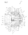
- FIG. 2 shows a possible variant 1a of the bearing 1 described above; details which are similar or identical to those already described are indicated by the same numbers for the sake of simplicity.
- the sleeve portion 26 of the ring-half 6 is formed as a cylindrical abutment portion with a smaller diameter than that of the ring-half 6 which projects from a shoulder 33 of the latter by a distance less than the length of the ring-half 5; this latter is fitted coaxially onto the abutment portion 26 so as to bear against the shoulder 33 and project at its end 29 beyond the ring-half 5 in such a way that the surfaces 24 and 25 are not flush but the surface 24 is offset outwardly relative to the surface 25.
- the screw 16 has a shank 18 with a thinner central portion 35; a washer 23, similar to that described earlier may, but need not, be interposed between the head 15 and the ring-half 5.
- the washer 23 (or, in its absence, the head 15 of the screw 16) bears against the surface 24 while an axial clearance 36 exists between the washer and the surface 25.
- this clearance would be taken up instantly by the resilient shortening of the shank 18 thanks to the reduction in the tension in the latter as a result of the release of the constraint constituted by the support defined by the surface 24; therefore, in this case as well, the clearance established between the balls 11, the ring 2 and the ring-half 5 during assembly is maintained constant.
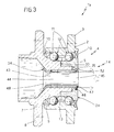
- a third embodiment is indicated 1b and is particularly suitable for bearings of larger diameter; similar or identical details to those described are indicated by the same numbers for the sake of simplicity.
- the ring-half 5 is similar to that of the bearing 1a of Figure 2 and has, in particular, a cylindrical abutment portion 26 of smaller diameter extending from a shoulder 33; in radial section, the ring-half 5 is substantially L-shaped and bears against the shoulder 33; there is a small predetermined clearance between the ring-half 5 and the end surface 25 of the abutment portion 26.
- the screw 16 is replaced by a tubular sleeve 44 of steel with a high modulus of elasticity and having a resilient ring 46 snap-engaged in an annular seat 47 formed in its end 45 so as to bear against the ring-half 5, specifically in an annular recess 52 in the end surface 24 of the ring-half 5.
- the sleeve 44 is clamped axially against the ring-half 6; specifically it is upset against the peripheral wall of the cavity 27.
- the sleeve 44 is assembled so as to place it in a state of resilient tensile stress; for example, the sleeve 44 is heated in order to cause its thermal expansion, passed through the through-hole 43 in the ring-half 6 (which, in this embodiment is not threaded but smooth), in the direction of the arrow in Figure 3 and as shown by the fine line, and finally its second end 48 is upset with a special tool, known and not shown in the drawing, possibly after further local heating of only the end 48, for example by induction, in order to deform the end 48 plastically and flare it so that it comes into cooperating contact- with the peripheral wall of the cavity 27.
- the ring-halves 5, 6 are tightly clamped in a pack between the axial shoulder formed by the flared end 48 and the opposing shoulder formed by the ring 46; in cooling, the tube 44 tends to shorten but as this is prevented by its cooperation at opposite ends with the ring-halves 5,6, it is placed under resilient tension.
- the function of the tubular sleeve 44 is therefore similar to that of the screw 16: if wear caused by relative rotation of the ring-half 5 on the ring-half 6 creates a clearance at the shoulder 33, the tubular sleeve 44 shortens by resilient recovery to take up the clearance and maintain the clearance established between the rolling elements 11, the outer ring 2 and the ring-half 5 during assembly.
- a further contribution to the resilience of the system is provided by the particular shape of the ring 5 as illustrated in Figure 3, that is, its L-shape in radial section.
- the tensioning of the sleeve 44 may also be obtained mechanically by providing the sleeve 44 with a threaded end 48 which can engage a correspondingly threaded portion of the ring-half 6, with the advantage that the magnitude of the axial tension in the sleeve 44 can be determined more precisely with the use of a predetermined tightening torque for the threaded portion 48.
- an axial clamping element such as the screw or the tubular sleeve housed in a through-hole in the second ring-half and suitably preloaded so as to be in a state of resilient tension enables the first ring-half to be kept constantly clamped axially onto the second ring-half without increasing the dimensions and/or the weight of the bearing and, above all, enables the same bearing to be used in the assemblies both of the driving wheels and the free wheels of a vehicle, the only additional operation required for bearings intended for driving wheel assemblies having to effect the necessary broaching to provide the grooved coupling for the constant velocity joint.
Landscapes
- Engineering & Computer Science (AREA)
- General Engineering & Computer Science (AREA)
- Mechanical Engineering (AREA)
- Rolling Contact Bearings (AREA)
Applications Claiming Priority (2)
| Application Number | Priority Date | Filing Date | Title |
|---|---|---|---|
| ITTO920240 | 1992-03-20 | ||
| ITTO920240A IT1259355B (it) | 1992-03-20 | 1992-03-20 | Cuscinetto di rotolamento, in particolare per un gruppo ruota di un veicolo |
Publications (3)
| Publication Number | Publication Date |
|---|---|
| EP0561377A2 true EP0561377A2 (fr) | 1993-09-22 |
| EP0561377A3 EP0561377A3 (fr) | 1994-03-23 |
| EP0561377B1 EP0561377B1 (fr) | 1997-07-16 |
Family
ID=11410254
Family Applications (1)
| Application Number | Title | Priority Date | Filing Date |
|---|---|---|---|
| EP93104345A Expired - Lifetime EP0561377B1 (fr) | 1992-03-20 | 1993-03-17 | Palier de roulement, en particulier pour roue de véhicule |
Country Status (3)
| Country | Link |
|---|---|
| EP (1) | EP0561377B1 (fr) |
| DE (1) | DE69312131T2 (fr) |
| IT (1) | IT1259355B (fr) |
Cited By (3)
| Publication number | Priority date | Publication date | Assignee | Title |
|---|---|---|---|---|
| EP0736398A3 (fr) * | 1995-04-06 | 1997-10-29 | Skf Ind Spa | Roulement à billes pour moyeu de roue de véhicule automobile |
| EP0980985A3 (fr) * | 1998-08-18 | 2001-01-03 | Nsk Ltd | Palier à double rangée de rouleaux côniques et son procédé d'assemblage |
| CN111702256A (zh) * | 2019-03-18 | 2020-09-25 | 罗伯特·博世有限公司 | 用于附件工具的轴承单元 |
Families Citing this family (1)
| Publication number | Priority date | Publication date | Assignee | Title |
|---|---|---|---|---|
| DE102019101653B4 (de) * | 2019-01-23 | 2024-03-21 | Dr. Ing. H.C. F. Porsche Aktiengesellschaft | Schutzanordnung |
Family Cites Families (11)
| Publication number | Priority date | Publication date | Assignee | Title |
|---|---|---|---|---|
| GB1297368A (fr) * | 1970-04-30 | 1972-11-22 | ||
| US3901568A (en) * | 1974-08-14 | 1975-08-26 | Gen Motors Corp | Rotary mechanism bearing arrangement |
| SE404331B (sv) * | 1975-07-07 | 1978-10-02 | Saab Scania Ab | Lagring for ett icke drivet hjul pa tyngre vegfordon |
| DE2843597A1 (de) * | 1978-10-06 | 1980-04-17 | Kugelfischer G Schaefer & Co | Zweireihige schraeglagerung fuer antreibbare kraftfahrzeugraeder |
| DE2940206A1 (de) * | 1979-10-04 | 1981-04-16 | MTU Motoren- und Turbinen-Union München GmbH, 8000 München | Drahtringlager |
| US4523864A (en) * | 1984-04-27 | 1985-06-18 | United Technologies Corporation | Tandem bearing construction |
| DE3736140A1 (de) * | 1987-10-26 | 1989-05-03 | Kugelfischer G Schaefer & Co | Radlagerung fuer kraftfahrzeuge |
| IT1219245B (it) * | 1988-04-27 | 1990-05-03 | Riv Officine Di Villar Perosa | Gruppo cuscinetto mozzo per ruote di autoveicoli |
| DE8806186U1 (de) * | 1988-05-10 | 1988-06-23 | Fa. Carl Zeiss, 7920 Heidenheim | Hochgenaues Kugellager |
| CH682813A5 (de) * | 1990-02-21 | 1993-11-30 | Fischer Ag Georg | Radlagerung. |
| FR2666389B1 (fr) * | 1990-09-04 | 1992-10-23 | Roulements Soc Nouvelle | Procede pour realiser une collerette de roulement et ensemble de roulement equipe d'une telle collerette. |
-
1992
- 1992-03-20 IT ITTO920240A patent/IT1259355B/it active IP Right Grant
-
1993
- 1993-03-17 EP EP93104345A patent/EP0561377B1/fr not_active Expired - Lifetime
- 1993-03-17 DE DE69312131T patent/DE69312131T2/de not_active Expired - Fee Related
Cited By (6)
| Publication number | Priority date | Publication date | Assignee | Title |
|---|---|---|---|---|
| EP0736398A3 (fr) * | 1995-04-06 | 1997-10-29 | Skf Ind Spa | Roulement à billes pour moyeu de roue de véhicule automobile |
| EP0980985A3 (fr) * | 1998-08-18 | 2001-01-03 | Nsk Ltd | Palier à double rangée de rouleaux côniques et son procédé d'assemblage |
| US6287015B1 (en) | 1998-08-18 | 2001-09-11 | Nsk Ltd. | Double row taper-roller bearing |
| US6502307B2 (en) | 1998-08-18 | 2003-01-07 | Nsk Ltd. | Double row taper-roller bearing and method of assembling the same bearing |
| EP1473474A3 (fr) * | 1998-08-18 | 2005-01-12 | Nsk Ltd | Moyeu pour véhicule |
| CN111702256A (zh) * | 2019-03-18 | 2020-09-25 | 罗伯特·博世有限公司 | 用于附件工具的轴承单元 |
Also Published As
| Publication number | Publication date |
|---|---|
| DE69312131D1 (de) | 1997-08-21 |
| EP0561377B1 (fr) | 1997-07-16 |
| ITTO920240A0 (it) | 1992-03-20 |
| DE69312131T2 (de) | 1997-11-20 |
| ITTO920240A1 (it) | 1993-09-20 |
| EP0561377A3 (fr) | 1994-03-23 |
| IT1259355B (it) | 1996-03-12 |
Similar Documents
| Publication | Publication Date | Title |
|---|---|---|
| US5328275A (en) | Unitized wheel hub and bearing assembly | |
| US5536075A (en) | Wheel hub unit for a vehicle | |
| US6126321A (en) | Shaft journal bearing and seal wear ring assembly | |
| US9541123B2 (en) | Cross-axis joint for a vehicle | |
| KR940011255B1 (ko) | 단일테이퍼 부싱 | |
| US4280598A (en) | Brake disk | |
| CA1114436A (fr) | Montage de roue et roulement a rouleaux coniques connexe | |
| PL309096A1 (en) | Vehicle wheel hub bearing arrangement and wheel hub assembly | |
| US20070098315A1 (en) | Bearing apparatus for a wheel of vehicle | |
| US5806936A (en) | Drive-wheel hub for a motor vehicle | |
| WO1995016143A1 (fr) | Ensemble palier a retenue axiale | |
| US5414784A (en) | Roller bearing assembly | |
| US5992943A (en) | Wheel end assembly | |
| EP0561377A2 (fr) | Palier de roulement, en particulier pour roue de véhicule | |
| EP0501506A2 (fr) | Support pour un élement fournant fou, en particulier pour une roue non-motrice d'un véhicule | |
| US3909920A (en) | Method of retaining an inner part within the bore of an outer part | |
| KR910012560A (ko) | 틴버클 조립체 | |
| JP2009150418A (ja) | 車輪用軸受装置 | |
| US20100150488A1 (en) | Bearing assembly | |
| US5284383A (en) | Adjusting and locking device for mounting a cycle wheel hub | |
| US4162618A (en) | Device for rolls in high speed rolling mills and the like | |
| JP2005529797A (ja) | 車輪をステアリング可能に懸架するための装置 | |
| JP2010241189A (ja) | 車輪用軸受装置 | |
| EP1395446B1 (fr) | Unite de support de moyeu avec demi-essieu separe | |
| JP2003130072A (ja) | 車輪用回転支持装置 |
Legal Events
| Date | Code | Title | Description |
|---|---|---|---|
| PUAI | Public reference made under article 153(3) epc to a published international application that has entered the european phase |
Free format text: ORIGINAL CODE: 0009012 |
|
| AK | Designated contracting states |
Kind code of ref document: A2 Designated state(s): DE FR GB |
|
| PUAL | Search report despatched |
Free format text: ORIGINAL CODE: 0009013 |
|
| AK | Designated contracting states |
Kind code of ref document: A3 Designated state(s): DE FR GB |
|
| 17P | Request for examination filed |
Effective date: 19940330 |
|
| 17Q | First examination report despatched |
Effective date: 19950307 |
|
| GRAG | Despatch of communication of intention to grant |
Free format text: ORIGINAL CODE: EPIDOS AGRA |
|
| GRAH | Despatch of communication of intention to grant a patent |
Free format text: ORIGINAL CODE: EPIDOS IGRA |
|
| GRAH | Despatch of communication of intention to grant a patent |
Free format text: ORIGINAL CODE: EPIDOS IGRA |
|
| GRAA | (expected) grant |
Free format text: ORIGINAL CODE: 0009210 |
|
| AK | Designated contracting states |
Kind code of ref document: B1 Designated state(s): DE FR GB |
|
| REF | Corresponds to: |
Ref document number: 69312131 Country of ref document: DE Date of ref document: 19970821 |
|
| ET | Fr: translation filed | ||
| PLBE | No opposition filed within time limit |
Free format text: ORIGINAL CODE: 0009261 |
|
| 26N | No opposition filed | ||
| REG | Reference to a national code |
Ref country code: GB Ref legal event code: IF02 |
|
| PGFP | Annual fee paid to national office [announced via postgrant information from national office to epo] |
Ref country code: GB Payment date: 20040310 Year of fee payment: 12 |
|
| PGFP | Annual fee paid to national office [announced via postgrant information from national office to epo] |
Ref country code: FR Payment date: 20040318 Year of fee payment: 12 |
|
| PGFP | Annual fee paid to national office [announced via postgrant information from national office to epo] |
Ref country code: DE Payment date: 20040430 Year of fee payment: 12 |
|
| PG25 | Lapsed in a contracting state [announced via postgrant information from national office to epo] |
Ref country code: GB Free format text: LAPSE BECAUSE OF NON-PAYMENT OF DUE FEES Effective date: 20050317 |
|
| PG25 | Lapsed in a contracting state [announced via postgrant information from national office to epo] |
Ref country code: DE Free format text: LAPSE BECAUSE OF NON-PAYMENT OF DUE FEES Effective date: 20051001 |
|
| GBPC | Gb: european patent ceased through non-payment of renewal fee |
Effective date: 20050317 |
|
| PG25 | Lapsed in a contracting state [announced via postgrant information from national office to epo] |
Ref country code: FR Free format text: LAPSE BECAUSE OF NON-PAYMENT OF DUE FEES Effective date: 20051130 |
|
| REG | Reference to a national code |
Ref country code: FR Ref legal event code: ST Effective date: 20051130 |