EP0561473A1 - Pendelhubantrieb mit Ausgleichgewicht für Sägen oder dergleichen - Google Patents
Pendelhubantrieb mit Ausgleichgewicht für Sägen oder dergleichen Download PDFInfo
- Publication number
- EP0561473A1 EP0561473A1 EP93200782A EP93200782A EP0561473A1 EP 0561473 A1 EP0561473 A1 EP 0561473A1 EP 93200782 A EP93200782 A EP 93200782A EP 93200782 A EP93200782 A EP 93200782A EP 0561473 A1 EP0561473 A1 EP 0561473A1
- Authority
- EP
- European Patent Office
- Prior art keywords
- cam
- gear
- rotation
- counterweight
- formations
- Prior art date
- Legal status (The legal status is an assumption and is not a legal conclusion. Google has not performed a legal analysis and makes no representation as to the accuracy of the status listed.)
- Granted
Links
Images


Classifications
-
- B—PERFORMING OPERATIONS; TRANSPORTING
- B23—MACHINE TOOLS; METAL-WORKING NOT OTHERWISE PROVIDED FOR
- B23D—PLANING; SLOTTING; SHEARING; BROACHING; SAWING; FILING; SCRAPING; LIKE OPERATIONS FOR WORKING METAL BY REMOVING MATERIAL, NOT OTHERWISE PROVIDED FOR
- B23D49/00—Machines or devices for sawing with straight reciprocating saw blades, e.g. hacksaws
- B23D49/10—Hand-held or hand-operated sawing devices with straight saw blades
- B23D49/16—Hand-held or hand-operated sawing devices with straight saw blades actuated by electric or magnetic power or prime movers
- B23D49/162—Pad sawing devices
- B23D49/165—Pad sawing devices with means to move the saw blades in an orbital path
-
- B—PERFORMING OPERATIONS; TRANSPORTING
- B23—MACHINE TOOLS; METAL-WORKING NOT OTHERWISE PROVIDED FOR
- B23D—PLANING; SLOTTING; SHEARING; BROACHING; SAWING; FILING; SCRAPING; LIKE OPERATIONS FOR WORKING METAL BY REMOVING MATERIAL, NOT OTHERWISE PROVIDED FOR
- B23D51/00—Sawing machines or sawing devices working with straight blades, characterised only by constructional features of particular parts; Carrying or attaching means for tools, covered by this subclass, which are connected to a carrier at both ends
- B23D51/16—Sawing machines or sawing devices working with straight blades, characterised only by constructional features of particular parts; Carrying or attaching means for tools, covered by this subclass, which are connected to a carrier at both ends of drives or feed mechanisms for straight tools, e.g. saw blades, or bows
- B23D51/161—Sawing machines or sawing devices working with straight blades, characterised only by constructional features of particular parts; Carrying or attaching means for tools, covered by this subclass, which are connected to a carrier at both ends of drives or feed mechanisms for straight tools, e.g. saw blades, or bows with dynamic balancing
-
- F—MECHANICAL ENGINEERING; LIGHTING; HEATING; WEAPONS; BLASTING
- F16—ENGINEERING ELEMENTS AND UNITS; GENERAL MEASURES FOR PRODUCING AND MAINTAINING EFFECTIVE FUNCTIONING OF MACHINES OR INSTALLATIONS; THERMAL INSULATION IN GENERAL
- F16F—SPRINGS; SHOCK-ABSORBERS; MEANS FOR DAMPING VIBRATION
- F16F7/00—Vibration-dampers; Shock-absorbers
- F16F7/10—Vibration-dampers; Shock-absorbers using inertia effect
-
- Y—GENERAL TAGGING OF NEW TECHNOLOGICAL DEVELOPMENTS; GENERAL TAGGING OF CROSS-SECTIONAL TECHNOLOGIES SPANNING OVER SEVERAL SECTIONS OF THE IPC; TECHNICAL SUBJECTS COVERED BY FORMER USPC CROSS-REFERENCE ART COLLECTIONS [XRACs] AND DIGESTS
- Y10—TECHNICAL SUBJECTS COVERED BY FORMER USPC
- Y10T—TECHNICAL SUBJECTS COVERED BY FORMER US CLASSIFICATION
- Y10T74/00—Machine element or mechanism
- Y10T74/18—Mechanical movements
- Y10T74/18056—Rotary to or from reciprocating or oscillating
- Y10T74/18248—Crank and slide
- Y10T74/18256—Slidable connections [e.g., scotch yoke]
Definitions
- the present invention relates to drive mechanisms for imparting orbital movement to saw blades or the like.
- the present invention relates to such an orbital drive mechanism having a counterbalancing member to minimize vibration.
- the present invention provides a new and improved orbital drive mechanism for a power operated reciprocating saw or the like.
- Another object of the present invention is the provision of an orbital drive mechanism for a power operated reciprocal saw or the like which minimizes vibration to the maximum extent by the use of an oscillatory counterweight mechanism.
- Still another object of the present invention is the provision of a drive mechanism of the type described which lends itself to compact construction by having the plunger assembly and the counterweight move in planes parallel with the plane of rotation of the drive gear.
- a power operated, reciprocating saw sometimes referred to in the trade as a recipro saw, is generally designated 10. It will be understood that the present invention has applicability to other types of power tools having orbiting reciprocating cutting members, such as a jigsaw.
- the power tool includes casing sections 12 and 14.
- the casing section 12 is preferably made in two parts, including the part 12a as shown in Figure 4.
- the casing section 14 includes a handle portion 15 mounting an operating trigger 16.
- the casing section 14 is generally hollow and receives an electric motor, such as a series or universal motor, including a stator 18 and an armature 20.
- the armature includes an armature or output shaft 22, one end of which is suitably mounted in a bearing assembly 24 supported by the casing 14.
- the armature shaft 22 includes a commutator 26 engaged by a pair of brushes 28. It will be understood that the drive mechanism of the present invention may be operated by other types of electric motors or even other types of motors, such as a pneumatic motor, for example.
- the output shaft 22 has the usual cooling fan 30 mounted thereon.
- the other or forward end of the output shaft 22 is supported by an annular bearing assembly 32, the latter being suitably mounted in the casing section 12a.
- a set of beveled pinion teeth 34 is formed on the forward end of the output shaft 22.
- the bearing 32 is received within annular opening 36 formed in a wall 38, the latter being integral with the housing part 12a.
- This same housing part includes an integral annular formation 40 which receives a dual ball bearing assembly 42.
- the dual ball bearing assembly 42 rotatably supports a shaft 44, the latter being suitably mounted in cantilever fashion in the formation 40 by a C-ring 46.
- the end 44a of the shaft 44 is suitably connected to a gear member, generally designated 48, for supporting the latter for rotation about the axis of the shaft 44.
- the gear member 48 includes an annular series of beveled teeth 50; these teeth mesh with the teeth 34 on the end of the motor output shaft 22. Thus, it is apparent that the gear member 48 is driven or rotated by the motor 18.
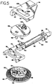
- the gear member 48 has an annular formation 52 suitably secured thereto. It is important to understand that this circular formation is eccentric with respect to the axis of rotation of the gear member 48. Further, the gear member 48 includes a pin 54 which may be characterized as a crank pin as it is eccentric with respect to the axis of rotation of the gear. The pin 54 rotatably supports a roller 56 through a suitable bearing arrangement.
- a plunger assembly is generally designated 60.
- This assembly includes a plunger 62 having a bracket assembly 64 at one end thereof for detachably mounting a saw blade 66 by means of fasteners 68.
- the other end of the plunger 62 is suitably connected to a blocklike member 70 which is connected to a plate 72 by means of fasteners 74.
- the plate 72 includes a rectilinear slot 76 defining opposed planar sidewalls 76a. It will be seen that the eccentrically mounted roller 56 is received within the slot 76 with diametrically opposed portions of the roller 56 respectively engaging portions of the planar surfaces 76a.
- the roller 56 and the slot 76 constitute, in essence, a scotch yoke assembly for imparting reciprocal movement to the plunger assembly upon rotation of the gear 48.
- the plate 72 includes opposed planar cam follower surfaces 78 and 80. These planar surfaces are engaged by the annular wall 52 at diametrically oppositely disposed portions on the latter. Since the annular formation 52 is eccentric with respect to the axis of rotation of the gear 48, it is apparent that oscillatory movement will be imparted to the plunger assembly 60 upon rotation of the gear 48 thereby to move the distal end portion of the blade 66 in an orbital path. This movement is orbital in nature because of the dual cam action imparted to the plunger assembly.
- the plunger 62 is slidably received within an annular bearing member, generally designated 82.
- the bearing 82 is received within an annular support 84 ( Figure 1) which is suitably mounted within the tool casing 12.
- the bearing 82 has frusto-conical formations 86 and 88 which cooperate with the inner surfaces of the bracket 84 to define spaces for receiving O-rings 90 and 92.
- These O-rings and the clearance spaces between the bearing 82 and the inside surfaces of the bracket 84 cooperate to provide a swivel or swinging mounting for the plunger assembly thereby to permit the oscillatory movement of the latter as referred to above.
- the bearing 82 cooperates with the planar surfaces 78 and 80 to mount the plunger assembly 60 for oscillating movement in the tool casing.
- the power tool 10 includes and adjustable foot plate, generally designated 94.
- This adjustable foot plate forms no part of the present invention and thus requires no further description herein.
- the eccentric crank pin 54 is adapted for threading engagement with a fastener 96.
- the fastener 96 is connected to a disk 98 and serves to mount the latter on the gear 48 for rotation with the latter.
- the disk 98 defines an annular peripheral formation 100; it is important to understand that this circular formation is eccentric with respect to the axis of rotation of the gear 48.
- the disk 98 supports an eccentric crank pin 102 which in turn mounts a roller 104 through a suitable bearing assembly. Before describing the primary functions of the disk 98, it should be pointed out that the disk 98 holds the plunger assembly plate 72 into engagement with the annular formation 52 and the roller 56 on the gear 48.
- the present invention includes a counterweight member 106 which has a mass substantially the same as the mass of the plunger assembly 60.
- the counterweight has a planar portion with a slot 108 defining opposed parallel planar formations 108a. It will be understood that the roller 104 is received within the slot 108 with diametrically opposed portions of the former in engagement with corresponding portions of the planar cam follower formations 108a. Thus, the roller 104 and slot 108 constitute, in effect, another scotch yoke mechanism for imparting reciprocal movement to counterweight 106 upon rotation of the gear 48.
- the counterweight 106 also includes opposed parallel planar surfaces 110, 112. These planar surfaces engage the annular peripheral formation 100 of the disk 98 at diametrically opposed locations on the latter. Since the disk 98 is eccentric with respect to the axis of rotation of the gear 48, it is apparent that the disk 98 will cooperate with the scotch yoke assembly to impart oscillatory movement to the counterweight 106 upon rotation of the gear 48.
- the counterweight 106 includes a further slot 114 which receives a stationary pin 116 mounted on a pedestal formation 118, the latter forming part of the casing part 12a.
- the slot 114 cooperates with the planar formations 108a, 110 and 112 for supporting the counterweight 106 for oscillatory movement.
- the counterweight is further held in place by a washer 120 having a diameter greater than the width of the slot 108.
- the washer is held in place by a retaining ring 122, the latter being suitably connected to the distal end of the crank pin 102.
- the slot 114 and pin 116 cooperate with the planar surfaces 110, 112 to mount the counterweight for oscillating movement in the tool casing. It will be apparent that this movement is essentially orbital in nature in view of the dual cam action imparted to the counterweight.
- crank pins 54 and 102 are in 180 degree relationship with each other. It will also be understood that the radial distance between the axis of rotation of the gear 48 and the axis of the pin 54 is the same as the distance between the axis of rotation of the gear 48 and the axis of the pin 102.
- the scotch yoke constituted by the roller 56 and slot 76 serves to move the plunger assembly 60 in one direction
- the other scotch yoke constituted by the roller 104 and slot 108 will move the counterweight 106 in an opposite direction.
- the eccentric axes of the annular formation 52 and the annular formation 100 are in 180 degree relationship with each other.
- the distance between the axis of rotation of the gear member 48 and the central axis of the formation 52 is the same as the distance between the axis of rotation of the gear 48 and the central axis of the annular formation 100. Accordingly, when the annular formation 52 serves to move the plunger assembly 60 in one direction, the annular formation 100 serves to move the counterweight in the opposite direction. It will also be understood that the various parts are designed so that the distance between the center of mass of the plunger assembly 60 and the center of mass of the counterweight 106 are at a minimum. Hence, in accordance with the present invention, vibration is reduced to a maximum extent.
- the present invention lends itself to very compact construction which is of great importance in the design of a portable power tool. This is achieved by having all principal parts of the drive mechanism sandwiched in close relationship and mounted for movement in planes parallel with the plane of rotation of the gear 48.
Landscapes
- Engineering & Computer Science (AREA)
- Mechanical Engineering (AREA)
- General Engineering & Computer Science (AREA)
- Sawing (AREA)
Applications Claiming Priority (2)
| Application Number | Priority Date | Filing Date | Title |
|---|---|---|---|
| US853108 | 1992-03-18 | ||
| US07/853,108 US5212887A (en) | 1992-03-18 | 1992-03-18 | Counterbalanced orbital drive mechanism for saws and the like |
Publications (2)
| Publication Number | Publication Date |
|---|---|
| EP0561473A1 true EP0561473A1 (de) | 1993-09-22 |
| EP0561473B1 EP0561473B1 (de) | 1998-01-21 |
Family
ID=25315077
Family Applications (1)
| Application Number | Title | Priority Date | Filing Date |
|---|---|---|---|
| EP93200782A Expired - Lifetime EP0561473B1 (de) | 1992-03-18 | 1993-03-17 | Pendelhubantrieb mit Ausgleichgewicht für Sägen oder dergleichen |
Country Status (6)
| Country | Link |
|---|---|
| US (1) | US5212887A (de) |
| EP (1) | EP0561473B1 (de) |
| JP (1) | JPH06198601A (de) |
| AU (1) | AU655390B2 (de) |
| CA (1) | CA2091807C (de) |
| DE (1) | DE69316413T2 (de) |
Cited By (10)
| Publication number | Priority date | Publication date | Assignee | Title |
|---|---|---|---|---|
| EP0768138A3 (de) * | 1995-10-10 | 1997-07-23 | Black & Decker Inc | Sägemaschine mit hin- und hergehendem Sägeblatt und drehbarer Sägeblatthalterung |
| US6286217B1 (en) | 1998-04-09 | 2001-09-11 | Black & Decker Inc. | Reciprocating saw with pivoted arm drive |
| GB2399615A (en) * | 2003-03-21 | 2004-09-22 | Black & Decker Inc | A vibration reduction apparatus for a power tool and a power tool incorporating such apparatus |
| US6944959B2 (en) | 1995-06-09 | 2005-09-20 | Black & Decker Inc. | Clamping arrangement for receiving a saw blade in multiple orientations |
| EP1666182A1 (de) | 2004-12-02 | 2006-06-07 | Makita Corporation | Hin- und herbewegbares Kraftwerkzeug |
| US7325315B2 (en) | 1995-06-09 | 2008-02-05 | Black & Decker Inc. | Clamping arrangement for receiving a saw blade in multiple orientations |
| US7363713B2 (en) * | 2003-06-23 | 2008-04-29 | Makita Corporation | Reciprocating power tool |
| US7506447B2 (en) | 2002-01-02 | 2009-03-24 | Black & Decker Inc. | Reciprocating saw |
| US9899899B2 (en) | 2013-10-25 | 2018-02-20 | Black & Decker Inc. | Handheld power tool with compact AC switch |
| CN113874147A (zh) * | 2019-03-26 | 2021-12-31 | 罗伯特·博世有限公司 | 手持式工具机 |
Families Citing this family (98)
| Publication number | Priority date | Publication date | Assignee | Title |
|---|---|---|---|---|
| USD344878S (en) | 1993-02-10 | 1994-03-08 | Shinano, Inc. | Air saw |
| US5421091A (en) * | 1994-02-23 | 1995-06-06 | S-B Power Tool Company | Adjustable guide shoe for reciprocating saw |
| US5702420A (en) * | 1994-06-14 | 1997-12-30 | Anthony R. Sterling And Tri-Tech, Inc. | Motorized suction punch forceps |
| US5598636A (en) * | 1994-08-17 | 1997-02-04 | Ryobi Motor Products | Reciprocating drive saw mechanism |
| US5584349A (en) * | 1995-03-16 | 1996-12-17 | Wilson; Randall W. | Mechanized tool |
| US5479711A (en) * | 1995-04-06 | 1996-01-02 | S-B Power Tool Company | Orbital and adjustable cant mechanism for reciprocating saws |
| EP0792712B1 (de) * | 1996-03-01 | 2002-05-08 | Black & Decker Inc. | Motorisierte Stichsäge |
| US6758119B1 (en) | 1996-08-19 | 2004-07-06 | Milwaukee Electric Tool Corporation | Reciprocating saw with rocker motion |
| US6508151B1 (en) | 1996-08-19 | 2003-01-21 | Milwaukee Electric Tool Corporation | Reciprocating saw with rocker motion |
| US5851141A (en) * | 1996-12-09 | 1998-12-22 | Elmore; Ronald W. | Elongated orbital power sander |
| US6021573A (en) * | 1997-05-15 | 2000-02-08 | Ryobi North America, Inc. | In-line oscillating cam assembly |
| GB9718305D0 (en) | 1997-08-30 | 1997-11-05 | Black & Decker Inc | Power tool |
| US7127973B2 (en) * | 1998-02-09 | 2006-10-31 | Milwaukee Electric Tool Corporation | Reciprocating saw |
| DE19819527A1 (de) * | 1998-04-30 | 1999-11-04 | Scintilla Ag | Hubstange für eine Elektrohandwerkzeugmaschine |
| US6189217B1 (en) * | 1998-06-17 | 2001-02-20 | Black & Decker Inc. | Power saw having blade storage chamber |
| US6249979B1 (en) * | 1998-08-13 | 2001-06-26 | Milwaukee Electric Tool Corporation | Orbital reciprocating saw |
| US6108916A (en) | 1998-08-14 | 2000-08-29 | Milwaukee Electric Tool Corporation | Movable handle for a power tool |
| US6094826A (en) * | 1998-09-01 | 2000-08-01 | Hobbico, Inc. | Reciprocating slot cutting tool |
| US6568089B1 (en) | 1999-06-04 | 2003-05-27 | Porter-Cable/Delta | Reciprocating saw having compact configuration and independent stability |
| JP3726576B2 (ja) * | 1999-08-11 | 2005-12-14 | 日立工機株式会社 | セーバソー |
| USD434627S (en) * | 1999-08-13 | 2000-12-05 | Black & Decker Inc. | Reciprocating saw |
| US6330835B1 (en) * | 2000-01-06 | 2001-12-18 | U.S. Filter Corporation | Scotch yoke mechanism for secure track sliding |
| USD440849S1 (en) | 2000-03-09 | 2001-04-24 | Hitachi Koki Co., Ltd. | Portable electric saw |
| US6357125B1 (en) | 2000-04-24 | 2002-03-19 | S-B Power Tool Company | Adjustable stroke mechanism for a scotch yoke assembly |
| KR20000063454A (ko) * | 2000-07-11 | 2000-11-06 | 이종락 | 수동겸용 가정용 소형전기톱. |
| USD487384S1 (en) | 2000-11-02 | 2004-03-09 | Milwaukee Electric Tool Corporation | Corded reciprocating saw |
| USD447924S1 (en) | 2000-11-02 | 2001-09-18 | Milwaukee Electric Tool Corporation | Handle arrangement for a reciprocating saw |
| CZ20031901A3 (cs) * | 2001-01-09 | 2003-11-12 | Black & Decker Inc. | Elektrický motor s kotvou potaženou tepelně vodivým plastem |
| JP2002355803A (ja) * | 2001-05-31 | 2002-12-10 | Nisca Corp | ステープル装置 |
| US6671969B2 (en) | 2001-12-18 | 2004-01-06 | Porter-Cable/Delta | Adjustable shoe for a reciprocating saw |
| US6658745B1 (en) * | 2002-07-02 | 2003-12-09 | Mountain Pneumatic Tools Co., Ltd. | Pneumatic power cutting tool |
| US20040148789A1 (en) * | 2002-08-20 | 2004-08-05 | Gist Leslie D. | Rotatable handle for reciprocating saws |
| DE10259568A1 (de) * | 2002-12-19 | 2004-07-01 | Hilti Ag | Pendelhubsäge mit einem Sekundärlagerelement |
| US7658012B2 (en) * | 2002-12-23 | 2010-02-09 | Milwaukee Electric Tool Corporation | Drive mechanism and power tool |
| JP4405195B2 (ja) | 2003-08-01 | 2010-01-27 | 株式会社マキタ | 往復動式電動工具 |
| JP2005052945A (ja) * | 2003-08-06 | 2005-03-03 | S P Air Kk | 自動ノコギリ |
| CN2671742Y (zh) * | 2004-01-12 | 2005-01-19 | 苏州宝时得电动工具有限公司 | 电动刀锯的偏心往复机构 |
| DE102004022361B4 (de) * | 2004-05-06 | 2007-06-06 | Hilti Ag | Hubsägewerkzeug |
| US20060117580A1 (en) * | 2004-10-16 | 2006-06-08 | Serdynski David P | Power tool and method of operating the same |
| US20070074407A1 (en) * | 2005-09-30 | 2007-04-05 | Serdynski David P | Tool and method of using same |
| WO2008061198A2 (en) | 2006-11-15 | 2008-05-22 | Milwaukee Electric Tool Corporation | Power tool |
| US7814666B2 (en) * | 2007-02-13 | 2010-10-19 | Robert Bosch Gmbh | Linkage drive mechanism for a reciprocating tool |
| US8549762B2 (en) * | 2007-02-13 | 2013-10-08 | Robert Bosch Gmbh | Linkage drive mechanism for a reciprocating tool |
| GB2469785B (en) | 2008-03-07 | 2012-12-19 | Milwaukee Electric Tool Corp | Reciprocating saw |
| US8407902B2 (en) | 2008-03-07 | 2013-04-02 | Milwaukee Electric Tool Corporation | Reciprocating power tool having a counterbalance device |
| US8230607B2 (en) | 2008-05-09 | 2012-07-31 | Milwaukee Electric Tool Corporation | Keyless blade clamp for a power tool |
| DE102008002212B4 (de) * | 2008-06-04 | 2016-10-06 | Hilti Aktiengesellschaft | Handgeführte Hubsägemaschine |
| DE102008043375B4 (de) | 2008-10-31 | 2021-11-11 | Hilti Aktiengesellschaft | Handgeführte Hubsägemaschine |
| CN201597020U (zh) * | 2009-07-01 | 2010-10-06 | 蔡吕乾 | 一种摆式工具工作头 |
| JP5474642B2 (ja) * | 2010-04-12 | 2014-04-16 | 株式会社マキタ | 往復動切断工具 |
| US20110315413A1 (en) * | 2010-06-25 | 2011-12-29 | Mako Surgical Corp. | Kit-Of Parts for Multi-Functional Tool, Drive Unit, and Operating Members |
| US11052476B2 (en) | 2010-07-23 | 2021-07-06 | Milwaukee Electric Tool Corporation | Reciprocating saw |
| US10875110B2 (en) | 2010-07-23 | 2020-12-29 | Milwaukee Electric Tool Corporation | Reciprocating saw |
| US9776263B2 (en) * | 2010-07-23 | 2017-10-03 | Milwaukee Electric Tool Corporation | Reciprocating saw |
| USD674263S1 (en) | 2010-10-15 | 2013-01-15 | Robert Bosch Gmbh | Saw |
| TWM404767U (en) * | 2010-12-21 | 2011-06-01 | Rea Lee Ind Co Ltd | Hand tools with reciprocation driving device |
| US9724771B2 (en) * | 2011-01-31 | 2017-08-08 | Makita Corporation | Reciprocating power tool |
| US9073563B2 (en) | 2011-05-18 | 2015-07-07 | Crystal Glass Canada Ltd. | Reciprocating power tool |
| US20130133210A1 (en) * | 2011-11-30 | 2013-05-30 | Robert Bosch Gmbh | Articulating Jig Saw |
| US10207347B2 (en) * | 2012-12-27 | 2019-02-19 | Robert Bosch Tool Corporation | Reciprocating tool with inverse bushing |
| CN104416225B (zh) * | 2013-09-05 | 2018-06-26 | 博世电动工具(中国)有限公司 | 往复锯 |
| JP2015199167A (ja) * | 2014-04-08 | 2015-11-12 | 株式会社マキタ | 電動工具 |
| JP6639797B2 (ja) * | 2015-04-01 | 2020-02-05 | 株式会社マキタ | レシプロソー |
| JP6953487B2 (ja) * | 2015-04-17 | 2021-10-27 | 株式会社マキタ | 往復動工具 |
| JP6584121B2 (ja) * | 2015-04-17 | 2019-10-02 | 株式会社マキタ | 往復動工具 |
| US11160721B2 (en) | 2015-06-20 | 2021-11-02 | Theragun, Inc. | Percussive therapy device with variable amplitude |
| US10702448B2 (en) * | 2017-03-14 | 2020-07-07 | Theragun, Inc. | Percussive massage device and method of use |
| US20180263845A1 (en) * | 2017-03-14 | 2018-09-20 | Theragun, LLC | Apparatus, system, and method for a reciprocating treatment device |
| US11957635B2 (en) | 2015-06-20 | 2024-04-16 | Therabody, Inc. | Percussive therapy device with variable amplitude |
| US10357425B2 (en) * | 2015-06-20 | 2019-07-23 | Theragun, LLC | Massage device and method of use |
| US10857064B2 (en) | 2018-12-26 | 2020-12-08 | Theragun, Inc. | Percussive therapy device |
| US20180264566A1 (en) * | 2017-03-20 | 2018-09-20 | Milwaukee Electric Tool Corporation | Reciprocating saw |
| CN108971628B (zh) * | 2017-05-31 | 2021-02-02 | 博世电动工具(中国)有限公司 | 电动工具 |
| CN109108912B (zh) * | 2017-06-26 | 2021-12-03 | 博世电动工具(中国)有限公司 | 电动工具 |
| WO2019235065A1 (ja) * | 2018-06-08 | 2019-12-12 | 工機ホールディングス株式会社 | 動力工具 |
| USD964134S1 (en) * | 2018-09-07 | 2022-09-20 | Jeremy Leman | Reciprocating saw |
| US11564860B2 (en) | 2018-12-26 | 2023-01-31 | Therabody, Inc. | Percussive therapy device with electrically connected attachment |
| US11432994B2 (en) | 2018-12-26 | 2022-09-06 | Therabody, Inc. | Intelligence engine system and method |
| US11890253B2 (en) | 2018-12-26 | 2024-02-06 | Therabody, Inc. | Percussive therapy device with interchangeable modules |
| US12064387B2 (en) | 2018-12-26 | 2024-08-20 | Therabody, Inc. | Percussive therapy device with electrically connected attachment |
| US11452670B2 (en) | 2018-12-26 | 2022-09-27 | Therabody, Inc. | Percussive therapy device with orientation, position, and force sensing and accessory therefor |
| US10959911B2 (en) | 2018-12-26 | 2021-03-30 | Theragun, Inc. | Percussive therapy device with active control |
| CN111989076B (zh) * | 2018-12-26 | 2022-03-15 | 泰乐甘股份有限公司 | 冲击式按摩装置及使用方法 |
| US10940081B2 (en) | 2019-05-07 | 2021-03-09 | Theragun, Inc. | Percussive massage device with force meter |
| US11357697B2 (en) | 2018-12-26 | 2022-06-14 | Therabody, Inc. | Percussive therapy device |
| US11813221B2 (en) | 2019-05-07 | 2023-11-14 | Therabody, Inc. | Portable percussive massage device |
| US11998504B2 (en) | 2019-05-07 | 2024-06-04 | Therabody, Inc. | Chair including percussive massage therapy |
| US11229963B2 (en) * | 2019-06-24 | 2022-01-25 | Black & Decker Inc. | Force and moment canceling reciprocating mechanism and power tool having same |
| US11453093B2 (en) * | 2019-06-24 | 2022-09-27 | Black & Decker Inc. | Reciprocating tool having planetary gear assembly and counterweighting assembly |
| US11857481B2 (en) | 2022-02-28 | 2024-01-02 | Therabody, Inc. | System for electrical connection of massage attachment to percussive therapy device |
| US11958121B2 (en) | 2022-03-04 | 2024-04-16 | Black & Decker Inc. | Reciprocating tool having orbit function |
| US12343809B2 (en) | 2022-03-09 | 2025-07-01 | Black & Decker Inc. | Reciprocating tool having orbit function |
| US11839964B2 (en) | 2022-03-09 | 2023-12-12 | Black & Decker Inc. | Counterbalancing mechanism and power tool having same |
| US12295900B1 (en) | 2022-12-21 | 2025-05-13 | Therabody, Inc. | Systems, methods, and devices for percussive massage therapy with voice activation |
| US12599978B2 (en) | 2023-03-01 | 2026-04-14 | Milwaukee Electric Tool Corporation | Reciprocating tool |
| US12402686B2 (en) | 2023-06-14 | 2025-09-02 | Therabody, Inc. | Articles of footwear having therapeutic assemblies |
| WO2025059992A1 (en) | 2023-09-21 | 2025-03-27 | Therabody, Inc. | Systems, methods, and devices for percussive massage therapy |
| US12466048B2 (en) | 2023-12-27 | 2025-11-11 | Black & Decker Inc. | Reciprocating tool having offset spur gear and counterweighting assembly |
Citations (3)
| Publication number | Priority date | Publication date | Assignee | Title |
|---|---|---|---|---|
| DE3222120A1 (de) * | 1981-07-24 | 1983-02-10 | AEG Power Tool Corp. (APTC), 06360 Norwich, Conn. | Tragbare saebelsaege |
| US4628605A (en) * | 1985-06-10 | 1986-12-16 | Porter-Cable Corporation | Orbital bayonet saw |
| US5079844A (en) * | 1990-11-13 | 1992-01-14 | Milwaukee Electric Tool Corporation | Counterbalanced reciprocating mechanism |
Family Cites Families (10)
| Publication number | Priority date | Publication date | Assignee | Title |
|---|---|---|---|---|
| US1643721A (en) * | 1927-09-27 | op cincinnati | ||
| US1648008A (en) * | 1925-12-01 | 1927-11-08 | Holland Furnace Co | Power-driven handsaw |
| US3729823A (en) * | 1971-05-05 | 1973-05-01 | Gardner Denver Co | Reciprocation drive and counterweight arrangement for power saws |
| US3971132A (en) * | 1971-09-17 | 1976-07-27 | Rockwell International Corporation | Saber saw |
| US4145811A (en) * | 1977-10-31 | 1979-03-27 | Jarvis Products Corporation | Reciprocating saw |
| DE2805012B2 (de) * | 1978-02-06 | 1980-03-27 | Reinhard Freund Maschinenbau, 4790 Paderborn | Stichsäge |
| US4238884A (en) * | 1979-06-19 | 1980-12-16 | Black & Decker Inc. | Orbital jig saw |
| US4272996A (en) * | 1979-06-19 | 1981-06-16 | Black & Decker Inc. | Scotch yoke having a curved track |
| US4545123A (en) * | 1984-04-09 | 1985-10-08 | Skil Corporation | Combination jig saw adjusting mechanism |
| US4976164A (en) * | 1988-11-14 | 1990-12-11 | Black & Decker Inc. | Thrust bearing arrangement for a power tool transmission |
-
1992
- 1992-03-18 US US07/853,108 patent/US5212887A/en not_active Expired - Lifetime
-
1993
- 1993-03-17 CA CA002091807A patent/CA2091807C/en not_active Expired - Fee Related
- 1993-03-17 DE DE69316413T patent/DE69316413T2/de not_active Expired - Lifetime
- 1993-03-17 AU AU35287/93A patent/AU655390B2/en not_active Ceased
- 1993-03-17 EP EP93200782A patent/EP0561473B1/de not_active Expired - Lifetime
- 1993-03-18 JP JP5058641A patent/JPH06198601A/ja active Pending
Patent Citations (3)
| Publication number | Priority date | Publication date | Assignee | Title |
|---|---|---|---|---|
| DE3222120A1 (de) * | 1981-07-24 | 1983-02-10 | AEG Power Tool Corp. (APTC), 06360 Norwich, Conn. | Tragbare saebelsaege |
| US4628605A (en) * | 1985-06-10 | 1986-12-16 | Porter-Cable Corporation | Orbital bayonet saw |
| US5079844A (en) * | 1990-11-13 | 1992-01-14 | Milwaukee Electric Tool Corporation | Counterbalanced reciprocating mechanism |
Cited By (16)
| Publication number | Priority date | Publication date | Assignee | Title |
|---|---|---|---|---|
| US7325315B2 (en) | 1995-06-09 | 2008-02-05 | Black & Decker Inc. | Clamping arrangement for receiving a saw blade in multiple orientations |
| US8046926B2 (en) | 1995-06-09 | 2011-11-01 | Black & Decker Inc. | Clamping arrangement for receiving a saw blade in multiple orientations |
| US6944959B2 (en) | 1995-06-09 | 2005-09-20 | Black & Decker Inc. | Clamping arrangement for receiving a saw blade in multiple orientations |
| US7003888B2 (en) | 1995-06-09 | 2006-02-28 | Black & Decker Inc. | Clamping arrangement for receiving a saw blade |
| EP0768138A3 (de) * | 1995-10-10 | 1997-07-23 | Black & Decker Inc | Sägemaschine mit hin- und hergehendem Sägeblatt und drehbarer Sägeblatthalterung |
| US5940977A (en) * | 1995-10-10 | 1999-08-24 | Black & Decker Inc. | Reciprocating saw with an angular blade drive and rotatable blade holder |
| US6286217B1 (en) | 1998-04-09 | 2001-09-11 | Black & Decker Inc. | Reciprocating saw with pivoted arm drive |
| US7506447B2 (en) | 2002-01-02 | 2009-03-24 | Black & Decker Inc. | Reciprocating saw |
| GB2399615B (en) * | 2003-03-21 | 2006-03-15 | Black & Decker Inc | Vibration reduction apparatus for power tool and power tool incorporating such apparatus |
| GB2399615A (en) * | 2003-03-21 | 2004-09-22 | Black & Decker Inc | A vibration reduction apparatus for a power tool and a power tool incorporating such apparatus |
| US7363713B2 (en) * | 2003-06-23 | 2008-04-29 | Makita Corporation | Reciprocating power tool |
| EP1666182A1 (de) | 2004-12-02 | 2006-06-07 | Makita Corporation | Hin- und herbewegbares Kraftwerkzeug |
| US7526868B2 (en) | 2004-12-02 | 2009-05-05 | Makita Corporation | Power tool with vibration reduction |
| US7743514B2 (en) | 2004-12-02 | 2010-06-29 | Makita Corporation | Reciprocating power tool |
| US9899899B2 (en) | 2013-10-25 | 2018-02-20 | Black & Decker Inc. | Handheld power tool with compact AC switch |
| CN113874147A (zh) * | 2019-03-26 | 2021-12-31 | 罗伯特·博世有限公司 | 手持式工具机 |
Also Published As
| Publication number | Publication date |
|---|---|
| DE69316413T2 (de) | 1998-05-14 |
| CA2091807A1 (en) | 1993-09-19 |
| CA2091807C (en) | 2003-08-12 |
| JPH06198601A (ja) | 1994-07-19 |
| US5212887A (en) | 1993-05-25 |
| DE69316413D1 (de) | 1998-02-26 |
| EP0561473B1 (de) | 1998-01-21 |
| AU655390B2 (en) | 1994-12-15 |
| AU3528793A (en) | 1993-09-23 |
Similar Documents
| Publication | Publication Date | Title |
|---|---|---|
| EP0561473B1 (de) | Pendelhubantrieb mit Ausgleichgewicht für Sägen oder dergleichen | |
| US5079844A (en) | Counterbalanced reciprocating mechanism | |
| CA2191264C (en) | Reciprocating drive mechanism | |
| US5134777A (en) | Adjustable stroke reciprocating mechanism for a power tool | |
| US5205043A (en) | Pendulum jigsaws | |
| US6021573A (en) | In-line oscillating cam assembly | |
| JP2860173B2 (ja) | 往復運動駆動機構 | |
| US4351112A (en) | Sabre saw bar and blade holder | |
| CN1290656C (zh) | 往复式锯 | |
| EP0907446B1 (de) | Stichsäge mit vorrichtung zum nach aussen drücken des hubstössels | |
| US2949944A (en) | Portable hand held saw | |
| US3962924A (en) | Double cam drive for a hedge trimmer having two reciprocating cutting blades | |
| US10850338B2 (en) | Electric power tool | |
| US20030051352A1 (en) | Reciprocating saw with flush blade | |
| GB2256906A (en) | Wobble plate drive | |
| JP2002283135A5 (ja) | セーバソー | |
| EP1297932A1 (de) | Kraftwerkzeug | |
| US3528463A (en) | Powered saw | |
| US4262420A (en) | Crosshead for sabre saws and sabre saws incorporating same | |
| JPH0630339Y2 (ja) | 往復動工具 | |
| JPH0767515A (ja) | 高効率空気モーター | |
| GB2234034A (en) | Drive mechanism for converting rotary motion into reciprocating linear motion | |
| GB2234033A (en) | Drive mechanism for converting rotary motion into reciprocating linear motion | |
| JP2004042211A (ja) | 往復動式電動工具 | |
| GB2234032A (en) | Drive mechanism for converting rotary motion into reciprocating linear motion |
Legal Events
| Date | Code | Title | Description |
|---|---|---|---|
| PUAI | Public reference made under article 153(3) epc to a published international application that has entered the european phase |
Free format text: ORIGINAL CODE: 0009012 |
|
| AK | Designated contracting states |
Kind code of ref document: A1 Designated state(s): DE FR GB IT NL SE |
|
| 17P | Request for examination filed |
Effective date: 19940322 |
|
| 17Q | First examination report despatched |
Effective date: 19960304 |
|
| GRAG | Despatch of communication of intention to grant |
Free format text: ORIGINAL CODE: EPIDOS AGRA |
|
| GRAG | Despatch of communication of intention to grant |
Free format text: ORIGINAL CODE: EPIDOS AGRA |
|
| GRAH | Despatch of communication of intention to grant a patent |
Free format text: ORIGINAL CODE: EPIDOS IGRA |
|
| GRAH | Despatch of communication of intention to grant a patent |
Free format text: ORIGINAL CODE: EPIDOS IGRA |
|
| ITF | It: translation for a ep patent filed | ||
| GRAA | (expected) grant |
Free format text: ORIGINAL CODE: 0009210 |
|
| AK | Designated contracting states |
Kind code of ref document: B1 Designated state(s): DE FR GB IT NL SE |
|
| PG25 | Lapsed in a contracting state [announced via postgrant information from national office to epo] |
Ref country code: NL Free format text: LAPSE BECAUSE OF FAILURE TO SUBMIT A TRANSLATION OF THE DESCRIPTION OR TO PAY THE FEE WITHIN THE PRESCRIBED TIME-LIMIT Effective date: 19980121 |
|
| REF | Corresponds to: |
Ref document number: 69316413 Country of ref document: DE Date of ref document: 19980226 |
|
| ET | Fr: translation filed | ||
| PG25 | Lapsed in a contracting state [announced via postgrant information from national office to epo] |
Ref country code: SE Free format text: LAPSE BECAUSE OF NON-PAYMENT OF DUE FEES Effective date: 19980318 |
|
| NLV1 | Nl: lapsed or annulled due to failure to fulfill the requirements of art. 29p and 29m of the patents act | ||
| PLBE | No opposition filed within time limit |
Free format text: ORIGINAL CODE: 0009261 |
|
| STAA | Information on the status of an ep patent application or granted ep patent |
Free format text: STATUS: NO OPPOSITION FILED WITHIN TIME LIMIT |
|
| EUG | Se: european patent has lapsed |
Ref document number: 93200782.6 |
|
| 26N | No opposition filed | ||
| PGFP | Annual fee paid to national office [announced via postgrant information from national office to epo] |
Ref country code: FR Payment date: 20000330 Year of fee payment: 8 |
|
| PGFP | Annual fee paid to national office [announced via postgrant information from national office to epo] |
Ref country code: GB Payment date: 20000609 Year of fee payment: 8 |
|
| PG25 | Lapsed in a contracting state [announced via postgrant information from national office to epo] |
Ref country code: GB Free format text: LAPSE BECAUSE OF NON-PAYMENT OF DUE FEES Effective date: 20010317 |
|
| GBPC | Gb: european patent ceased through non-payment of renewal fee |
Effective date: 20010317 |
|
| PG25 | Lapsed in a contracting state [announced via postgrant information from national office to epo] |
Ref country code: FR Free format text: LAPSE BECAUSE OF NON-PAYMENT OF DUE FEES Effective date: 20011130 |
|
| REG | Reference to a national code |
Ref country code: FR Ref legal event code: ST |
|
| PG25 | Lapsed in a contracting state [announced via postgrant information from national office to epo] |
Ref country code: IT Free format text: LAPSE BECAUSE OF NON-PAYMENT OF DUE FEES;WARNING: LAPSES OF ITALIAN PATENTS WITH EFFECTIVE DATE BEFORE 2007 MAY HAVE OCCURRED AT ANY TIME BEFORE 2007. THE CORRECT EFFECTIVE DATE MAY BE DIFFERENT FROM THE ONE RECORDED. Effective date: 20050317 |
|
| PGFP | Annual fee paid to national office [announced via postgrant information from national office to epo] |
Ref country code: DE Payment date: 20120502 Year of fee payment: 20 |
|
| REG | Reference to a national code |
Ref country code: DE Ref legal event code: R071 Ref document number: 69316413 Country of ref document: DE |
|
| PG25 | Lapsed in a contracting state [announced via postgrant information from national office to epo] |
Ref country code: DE Free format text: LAPSE BECAUSE OF EXPIRATION OF PROTECTION Effective date: 20130319 |