EP0561570A2 - Fernsehnormunterscheidungsvorrichtung - Google Patents
Fernsehnormunterscheidungsvorrichtung Download PDFInfo
- Publication number
- EP0561570A2 EP0561570A2 EP93301897A EP93301897A EP0561570A2 EP 0561570 A2 EP0561570 A2 EP 0561570A2 EP 93301897 A EP93301897 A EP 93301897A EP 93301897 A EP93301897 A EP 93301897A EP 0561570 A2 EP0561570 A2 EP 0561570A2
- Authority
- EP
- European Patent Office
- Prior art keywords
- signal
- television signal
- type
- horizontal synchronizing
- polarity
- Prior art date
- Legal status (The legal status is an assumption and is not a legal conclusion. Google has not performed a legal analysis and makes no representation as to the accuracy of the status listed.)
- Granted
Links
Images



Classifications
-
- H—ELECTRICITY
- H04—ELECTRIC COMMUNICATION TECHNIQUE
- H04N—PICTORIAL COMMUNICATION, e.g. TELEVISION
- H04N5/00—Details of television systems
- H04N5/44—Receiver circuitry for the reception of television signals according to analogue transmission standards
- H04N5/46—Receiver circuitry for the reception of television signals according to analogue transmission standards for receiving on more than one standard at will
-
- H—ELECTRICITY
- H04—ELECTRIC COMMUNICATION TECHNIQUE
- H04N—PICTORIAL COMMUNICATION, e.g. TELEVISION
- H04N7/00—Television systems
- H04N7/015—High-definition television systems
- H04N7/0152—High-definition television systems using spatial or temporal subsampling
Definitions
- This invention relates to a television signal discriminating apparatus suitable to distinguish between a MUSE (Multiple Sub-Nyquist Sampling Encode) signal which is a form of a transmission signal of high definition television and a popular television signal.
- MUSE Multiple Sub-Nyquist Sampling Encode
- BS NTSC broadcasting and MUSE broadcasting are alternatively transmitted to a same channel, for example in BS broadcasting.
- the two transmission systems are quite different in processing of both of an image and sound from each other. Accordingly, it is necessary to discriminate the kind of received signal to change over the processing or mute (erase) both or one of an image and sound.
- a received signal is a MUSE signal is discriminated by detecting frame pulses which are a reference signal for each frame inserted in a MUSE signal.
- detection of frame pulses over a plurality of frames based on a flywheel effect is performed taking a detection error of the frame pulses by noise or by some other factor into consideration.
- a first television signal for example, a MUSE signal
- a horizontal synchronizing signal has a signal portion of a first polarity, another signal portion of a second polarity opposite to the first polarity, and a further signal portion of a level intermediate between the first and second polarities and a second television signal (for example, an NTSC signal) wherein a horizontal synchronizing signal consists only of signals of the first polarity.
- a television signal kind discriminating apparatus for discriminating an input television signal between a first television signal wherein a horizontal synchronizing signal has a signal portion of a first polarity, another signal portion having a second polarity opposite to the first polarity, and a further signal portion having a level intermediate between the first and second polarities, and a second television signal wherein a horizontal synchronizing signal consists only of signals of the first polarity, which level comparison means for converting the input television signal into a binary signal using a value between the first and second polarity signal portions of the horizontal synchronizing signal of the first television signal as a threshold value, delay means for delaying the binary signal outputted from the level comparison means by a predetermined time, exclusive OR gate means for outputting an exclusive OR between the binary signal outputted from the level comparison means and the binary signal outputted from the delay means, mid-point position detection means for detecting a temporal position of a mid point of the horizontal synchron
- an input television signal is converted into a binary signal using a value between the first and second polarity signal portions of the horizontal synchronizing signal of the first television signal as a threshold value, and the binary signal is delayed by the predetermined time by the delay means.
- An exclusive OR signal between the binary signal not delayed and the binary signal delayed is outputted from the exclusive OR gate means, and a temporal position of a mid point of the horizontal synchronizing signal of the input television signal is detected by the mid-point position detecting means.
- the input television signal is the first television signal or the second television signal is discriminated based on the exclusive OR signal within the predetermined time after the detected temporal position of the mid point of the horizontal synchronizing signal. Accordingly, the kind of the television signal can be discriminated in a very short time comparing with conventional television signal kind discriminating apparatus.
- a television signal kind discriminating apparatus for discriminating an input television signal between a first television signal wherein a horizontal synchronizing signal has a signal portion of a first polarity, another signal portion having a second polarity opposite to the first polarity, and a further signal portion having a level intermediate between the first and second polarities, and a second television signal wherein a horizontal synchronizing signal consists only of signals of the first polarity, which comprises signal converting means for converting the input television signal from an analog signal into a digital signal and outputting a most significant bit signal representative of a most significant bit of the digital signal, delay means for delaying the most significant bit signal outputted from the signal converting means by a predetermined time, exclusive OR gate means for outputting an exclusive OR between the most significant bit signal outputted from the signal converting means and the most significant bit signal outputted from the delay means, mid-point position detection means for detecting a temporal position of a mid point of the horizontal synchronizing signal of the input television
- an input television signal is supplied to the signal converting means, and a most significant bit signal outputted from the signal converting means is delayed by the predetermined time by the delay means.
- An exclusive OR signal between the most significant bit signal outputted from the signal converting means and the most significant bit signal delayed by the delay means is outputted from the exclusive OR gate means, and a temporal position of a mid point of the horizontal synchronizing signal of the input television signal is detected by the mid-point position detecting means.
- the input television signal is the first. television signal or the second television signal is discriminated based on the exclusive OR signal within the predetermined time after the detected temporal position of the mid point of the horizontal synchronizing signal. Accordingly, the kind of the television signal can be discriminated in a very short time comparing with conventional television signal kind discriminating apparatus.
- the television signal kind discriminating apparatus of the present embodiment is generally constructed such that it distinguishes between a MUSE signal wherein a horizontal synchronizing signal is a three-value synchronizing signal and has a signal portion of a first polarity (for example, the negative polarity), another signal portion of a second polarity (for example, the positive polarity) opposite to the first polarity, and a further signal portion of a level intermediate between the first and second polarities, and a popular television signal wherein a horizontal synchronizing signal consists only of signals of the first polarity (for example, the negative polarity), such as, for example, an NTSC signal.
- a horizontal synchronizing signal is a three-value synchronizing signal and has a signal portion of a first polarity (for example, the negative polarity), another signal portion of a second polarity (for example, the positive polarity) opposite to the first polarity, and a further signal portion of a level intermediate between the first and second polarities,
- the television signal kind discriminating apparatus shown includes a level comparator 2 for converting an input television signal S1 into a binary signal S2 having two high ("H") and low ("L") levels using a signal of an intermediate or mid-point level between a first polarity signal portion and a second polarity signal portion of a horizontal synchronizing signal of a MUSE signal outputted from a horizontal synchronization mid-point level generator 4 as a threshold value and outputting the thus produced binary signal S2.
- a delay circuit 6 delays the binary signal S2 outputted from the level comparator 2 by a time ⁇ and outputs it as a signal S3.
- An exclusive OR gate 8 outputs an exclusive OR signal S4 between the binary signal S2 outputted from the level comparator 2 and the binary signal S3 outputted from the delay circuit 6.
- the exclusive OR signal S4 is supplied to a data input terminal of a latch circuit 10.
- the latch circuit 10 outputs a signal supplied to the data input terminal thereof when a signal supplied to a G input terminal thereof is at the "H” level, but holds, when the signal supplied to the G input terminal thereof is at the "L” level, a signal supplied to the data input terminal thereof at a falling edge of the signal supplied to the G input terminal thereof.
- a horizontal synchronization mid-point position detector 12 detects a temporal position of a mid point of a horizontal synchronizing signal of the input television signal and outputs a signal indicative of the position.
- a delay circuit 14 delays the output signal of the horizontal synchronization mid-point position detecting circuit 12 by a time ⁇ /2 and supplies a signal S5 thus obtained to the G input terminal of the latch circuit 10.
- the output signal S6 of the latch circuit 10 is supplied to a frequency detecting circuit 16.
- the frequency detecting circuit 16 has a threshold value of a suitable frequency for the "H" level of the input signal S6, and determines, when the input signal S6 presents the "H” level in a high frequency, that the input television signal S2 is a MUSE signal, but determines, when the input signal S6 presents the "H” level in a low frequency (that is, presents the "L” level in a high frequency), that the input television signal S2 is a popular television signal such as, for example, an NTSC signal.
- the frequency detecting circuit 16 can assume various configurations such as a configuration which includes, for example, an integrator of a suitable time constant consisting of a resistor and a capacitor, and a comparator having a suitable threshold value, or another configuration which includes a counter for counting the period of the "H" or "L" level of the input signal S6.
- the latch circuit 10, the delay circuit 14 and the frequency detecting circuit 16 described above constitutes discriminating means for discriminating, based on the output of the exclusive OR gate 8 within the delay time ⁇ by the delay circuit 6 after the temporal position of the mid point of the horizontal synchronizing signal detected by the horizontal synchronization mid-point position detector 12, which one of a MUSE signal and a popular television signal such as, for example, an NTSC signal the input television signal is.
- Fig. 2 illustrates operation of the television signal kind discriminating apparatus of Fig. 1 when the input television signal S1 is a MUSE signal.
- the horizontal synchronizing signal of the MUSE signal is a three-value synchronizing signal and is reversed for each horizontal period as seen from the waveform (a) of Fig. 2.
- the MUSE signal is compared in level by the level comparator 2 with a mid-point level of the horizontal synchronizing signal of the MUSE signal as a threshold level so that it is converted into a binary signal S2 (refer to the waveform (b) of Fig. 2).
- the binary signal S2 is delayed by the time ⁇ by the delay circuit 6 to make a binary signal S3 (refer to the waveform (c) of Fig. 2).
- the exclusive OR gate 8 outputs an exclusive OR signal S4 between the binary signal S2 outputted from the level comparator 2 and the binary signal S3 outputted from the delay circuit 6 (refer to the waveform (d) of Fig. 2).
- the exclusive OR signal S4 presents the "H" level for the time ⁇ after the mid-point position of the horizontal synchronizing signal of the MUSE signal S1 and is supplied to the data input terminal of the latch circuit 10.
- the horizontal synchronization mid-point position detector 12 detects the temporal position of a mid point of the horizontal synchronizing signal of the MUSE signal S1 and outputs a signal indicative of the position.
- the delay circuit 14 delays the output signal of the horizontal synchronization mid-point position detecting circuit 12 by the time ⁇ /2 and supplies a thus obtained signal S5 (refer to the waveform (e) of Fig. 2) to the G input terminal of the latch circuit 10.
- the exclusive OR signal S4 which presents the "H" level for the time ⁇ after the mid-point position of the horizontal synchronizing signal of the MUSE signal S1 is detected by the latch circuit 10 at a point of time delayed by the time ⁇ /2 after the mid-point position of the horizontal synchronizing signal of the MUSE signal S1, and a signal S6 ("H") indicative of a result of the detection (refer to the waveform (f) of Fig. 2) is supplied to the frequency detecting circuit 16.
- the output signal S6 of the latch circuit 10 presents "H" for the full period. Consequently, the frequency detecting circuit 16 discriminates that the input television signal is a MUSE signal.
- the output signal S6 of the latch circuit 10 always presents the "H" level when the input television signal S1 is a MUSE signal, it is estimated that the output signal S6 may present the "L" level in a low frequency due to an influence of noise, but since the threshold value of a suitable frequency is set in the frequency detecting circuit 16, the frequency detecting circuit 16 can discriminate with certainty that the input television signal is a MUSE signal.
- the frequency detecting circuit 16 determines that the input television signal is a popular television signal such as an NTSC signal.
- the input television signal S1 is an NTSC signal
- the horizontal synchronizing signal of the NTSC signal has the form of a negative pulse
- the output of the level comparator 2 does not present a change-over between the "H” and "L” levels at any position within the horizontal synchronizing signal at all. Consequently, the position of an output pulse of the exclusive OR gate 8 does not come within the period of the horizontal synchronizing signal.
- the output of the horizontal synchronization mid-point position detector 12 comes within the horizontal synchronizing signal, and consequently, the output of the latch circuit 10 presents the "L" level.
- the kind of a television signal can be discriminated in a very short time from several horizontal periods (H) to ten and several horizontal periods (H).
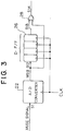
- the modified television signal kind discriminating apparatus includes, in place of the level comparator 2, the horizontal synchronization mid-point level generator 4, the delay circuit 6 and the exclusive OR circuit 8 of Fig.
- an analog to digital (A/D) converter 22 for converting an input television signal S1 from an analog into a digital signal and outputting a most significant bit (MSB) signal S12 representative of a most significant bit of the thus obtained digital signal
- a shift register 26 for delaying the most significant bit signal S12 outputted from the analog to digital converter 22 by a time ⁇ and outputting it as a signal S13
- an exclusive OR gate 26 for outputting an exclusive OR between the most significant bit signal S12 outputted from the analog to digital converter 22 and the most significant bit signal S13 outputted from the shift register 26.
- the shift register 26 may be constituted from a plurality of D-type flip-flops (synchronous flip-flops).
- the output signal S14 of the exclusive OR gate 28 is supplied to the data input terminal of the latch circuit 10 of Fig. 1.
- the most significant bit signal S12 outputted from the analog to digital converter 22, that is, the most significant bit (MSB) of the MUSE signal after conversion into a digital signal, is itself a binary signal with a mid-point level of a horizontal synchronizing signal of the MUSE signal employed as a threshold value, and the shift register 26 delays the most significant bit signal S12 by the time ⁇ .
- the exclusive OR gate 28 receives the most significant bit signal S12 from the analog to digital converter 22 and the most significant bit signal outputted from the shift register 26.
- the exclusive OR signal S14 from the exclusive OR circuit 28 is supplied to the latch circuit 10 and then to the frequency detecting circuit 16 so that the kind of the input television signal S1 is discriminated by the frequency detecting circuit 16 as described hereinabove.
- Fig. 4 shows an example wherein a discrimination signal obtained by the television signal kind discriminating apparatus and another discrimination signal obtained based on frame pulse detection by a conventional television signal kind discriminating apparatus are combined to make a new discrimination signal.
- a signal indicative of a MUSE processing effective period shown by the waveform (c) of Fig. 4 can be obtained By logically ANDing the discrimination signal obtained by the television signal kind discriminating apparatus of the present invention shown by the waveform (a) of Fig. 4 and the discrimination signal by the conventional television signal kind discriminating apparatus shown by the waveform (b) of Fig. 4, Meanwhile, another signal indicative of an NTSC effective period shown by the waveform (d) of Fig.
- a mute signal shown by the waveform (e) of Fig. 4 can be obtained by logically ANDing the discrimination signal by the television signal kind discriminating apparatus of the present invention shown by the waveform (a) of Fig. 4 and the discrimination signal by the conventional television signal kind discriminating apparatus shown by the waveform (b) of Fig. 4 and inverting a result of the logical ANDing.
- a mute signal shown by the waveform (e) of Fig. 4 can be obtained by logically ANDing the discrimination signal by the television signal kind discriminating apparatus of the present invention shown by the waveform (a) of Fig. 4 and the discrimination signal by the conventional television signal kind discriminating apparatus shown by the waveform (b) of Fig. 4,
- the signal indicative of the MUSE processing effective period, the signal indicative of the NTSC processing effective signal and the mute signal obtained in this manner are more accurate than ever.
Landscapes
- Engineering & Computer Science (AREA)
- Multimedia (AREA)
- Signal Processing (AREA)
- Television Systems (AREA)
- Synchronizing For Television (AREA)
Applications Claiming Priority (2)
| Application Number | Priority Date | Filing Date | Title |
|---|---|---|---|
| JP4091681A JPH05268545A (ja) | 1992-03-17 | 1992-03-17 | テレビジョン信号種類判別装置 |
| JP91681/92 | 1992-03-17 |
Publications (3)
| Publication Number | Publication Date |
|---|---|
| EP0561570A2 true EP0561570A2 (de) | 1993-09-22 |
| EP0561570A3 EP0561570A3 (de) | 1994-02-09 |
| EP0561570B1 EP0561570B1 (de) | 1997-07-09 |
Family
ID=14033241
Family Applications (1)
| Application Number | Title | Priority Date | Filing Date |
|---|---|---|---|
| EP93301897A Expired - Lifetime EP0561570B1 (de) | 1992-03-17 | 1993-03-12 | Fernsehnormunterscheidungsvorrichtung |
Country Status (4)
| Country | Link |
|---|---|
| US (1) | US5307165A (de) |
| EP (1) | EP0561570B1 (de) |
| JP (1) | JPH05268545A (de) |
| DE (1) | DE69311936T2 (de) |
Cited By (1)
| Publication number | Priority date | Publication date | Assignee | Title |
|---|---|---|---|---|
| WO1997041664A3 (en) * | 1996-04-30 | 1997-12-18 | Philips Electronics Nv | Synchronization of multistandard television apparatus |
Families Citing this family (7)
| Publication number | Priority date | Publication date | Assignee | Title |
|---|---|---|---|---|
| US5566214A (en) * | 1995-06-19 | 1996-10-15 | Westinghouse Electric Company | Automatic noise normalization and reacquisition control for a QPSK demodulator symbol tracking loop |
| US5828402A (en) * | 1996-06-19 | 1998-10-27 | Canadian V-Chip Design Inc. | Method and apparatus for selectively blocking audio and video signals |
| KR100224861B1 (ko) * | 1997-08-01 | 1999-10-15 | 윤종용 | 수신 신호 판별회로 및 그 방법 |
| US6366327B1 (en) * | 1997-12-22 | 2002-04-02 | Texas Instruments Incorporated | Vertical sync detection and output for video decoder |
| JP2002077664A (ja) * | 2000-08-31 | 2002-03-15 | Matsushita Electric Ind Co Ltd | 2値/3値同期信号検出装置 |
| KR100407961B1 (ko) * | 2001-07-05 | 2003-12-03 | 엘지전자 주식회사 | 영상표시기기의 입력신호 처리장치 |
| JP3670648B2 (ja) * | 2003-02-07 | 2005-07-13 | 新光電子株式会社 | 荷重測定機構 |
Family Cites Families (13)
| Publication number | Priority date | Publication date | Assignee | Title |
|---|---|---|---|---|
| JPH01221068A (ja) * | 1988-02-29 | 1989-09-04 | Matsushita Electric Ind Co Ltd | テレビジョン信号受信装置 |
| JPH01236782A (ja) * | 1988-03-16 | 1989-09-21 | Matsushita Electric Ind Co Ltd | テレビジョン信号受信装置 |
| DE3828415C2 (de) * | 1988-08-20 | 1996-04-11 | Broadcast Television Syst | Verfahren und Schaltung zur Ableitung von H- und V-frequenten Synchronimpulsen |
| US4860098A (en) * | 1988-09-19 | 1989-08-22 | The Grass Valley Group, Inc. | Video discrimination between different video formats |
| JPH02100483A (ja) * | 1988-10-07 | 1990-04-12 | Hitachi Ltd | テレビジョン信号の信号処理装置 |
| JP2663565B2 (ja) * | 1988-10-24 | 1997-10-15 | ソニー株式会社 | Muse方式判別回路 |
| JPH02237280A (ja) * | 1989-03-10 | 1990-09-19 | Hitachi Ltd | 標準/高品位テレビジョン受信装置 |
| JP2896162B2 (ja) * | 1989-05-31 | 1999-05-31 | 株式会社東芝 | 冷凍サイクル装置 |
| JPH0360585A (ja) * | 1989-07-29 | 1991-03-15 | Sony Corp | テレビジョン受像機 |
| JP2842913B2 (ja) * | 1990-01-24 | 1999-01-06 | 株式会社日立製作所 | ワイドテレビジョン信号処理回路 |
| JP2925023B2 (ja) * | 1990-02-26 | 1999-07-26 | 三菱電機株式会社 | Muse方式ハイビジョン信号受信装置 |
| US5027058A (en) * | 1990-02-26 | 1991-06-25 | Tektronix, Inc. | Multi-standard video option for oscilloscope |
| JPH04352580A (ja) * | 1991-05-30 | 1992-12-07 | Toshiba Corp | テレビジョン受像機 |
-
1992
- 1992-03-17 JP JP4091681A patent/JPH05268545A/ja not_active Withdrawn
-
1993
- 1993-03-10 US US08/029,342 patent/US5307165A/en not_active Expired - Fee Related
- 1993-03-12 DE DE69311936T patent/DE69311936T2/de not_active Expired - Fee Related
- 1993-03-12 EP EP93301897A patent/EP0561570B1/de not_active Expired - Lifetime
Cited By (1)
| Publication number | Priority date | Publication date | Assignee | Title |
|---|---|---|---|---|
| WO1997041664A3 (en) * | 1996-04-30 | 1997-12-18 | Philips Electronics Nv | Synchronization of multistandard television apparatus |
Also Published As
| Publication number | Publication date |
|---|---|
| DE69311936T2 (de) | 1998-01-22 |
| JPH05268545A (ja) | 1993-10-15 |
| EP0561570A3 (de) | 1994-02-09 |
| EP0561570B1 (de) | 1997-07-09 |
| DE69311936D1 (de) | 1997-08-14 |
| US5307165A (en) | 1994-04-26 |
Similar Documents
| Publication | Publication Date | Title |
|---|---|---|
| KR100307979B1 (ko) | 보조비디오데이타슬라이서 | |
| US6823025B2 (en) | Amplitude modulation detector | |
| JPH02134996A (ja) | ビデオ信号情報付加装置及びビデオ信号の付加情報検知装置 | |
| US5025496A (en) | Odd/even field detector for video signals | |
| JPH04506731A (ja) | ビット誤り率検出 | |
| US5307165A (en) | Television signal kind discriminating apparatus | |
| JP3694529B2 (ja) | ディジタルテレビジョンの同期化 | |
| CA1189960A (en) | Television signal amplitude detection circuit | |
| KR0178718B1 (ko) | 복합영상신호에 실린 디지탈데이타를 위한 검출클럭발생장치 및 검출클럭을 이용한 데이타검출장치 | |
| CA1287682C (en) | Clamping circuit for clamping video signal | |
| US6151374A (en) | Synchronizing signal detecting apparatus | |
| KR100230026B1 (ko) | 클럭 기준 펄스의 시퀀스를 검출하기 위한 방법과 장치 | |
| US4864400A (en) | Television synchronization system | |
| JPS61172494A (ja) | バ−ストゲ−ト・パルス発生器 | |
| US4631587A (en) | Field responsive vertical pulse generator | |
| US7046301B2 (en) | Vertical synchronous signal detection circuit | |
| US6281934B1 (en) | Data slicing device and data slicing method for extracting data from a signal | |
| KR100300947B1 (ko) | 디지털텔레비젼수신장치의세그먼트동기신호검출장치 | |
| JP3603962B2 (ja) | ビデオ信号中の情報検出装置 | |
| US5390030A (en) | Peak holding circuit and video processing unit using the same | |
| EP0580287B1 (de) | Verfahren und Gerät zum Feststellen von Bildsynchronisationssignalen | |
| JPS6143886A (ja) | デ−タ識別回路 | |
| JPS6151473B2 (de) | ||
| JPH11505399A (ja) | 垂直同期信号検出器 | |
| JP2793726B2 (ja) | 水平同期信号検出装置 |
Legal Events
| Date | Code | Title | Description |
|---|---|---|---|
| PUAI | Public reference made under article 153(3) epc to a published international application that has entered the european phase |
Free format text: ORIGINAL CODE: 0009012 |
|
| AK | Designated contracting states |
Kind code of ref document: A2 Designated state(s): DE FR GB |
|
| PUAL | Search report despatched |
Free format text: ORIGINAL CODE: 0009013 |
|
| AK | Designated contracting states |
Kind code of ref document: A3 Designated state(s): DE FR GB |
|
| 17P | Request for examination filed |
Effective date: 19940721 |
|
| GRAG | Despatch of communication of intention to grant |
Free format text: ORIGINAL CODE: EPIDOS AGRA |
|
| 17Q | First examination report despatched |
Effective date: 19961002 |
|
| GRAH | Despatch of communication of intention to grant a patent |
Free format text: ORIGINAL CODE: EPIDOS IGRA |
|
| GRAH | Despatch of communication of intention to grant a patent |
Free format text: ORIGINAL CODE: EPIDOS IGRA |
|
| GRAA | (expected) grant |
Free format text: ORIGINAL CODE: 0009210 |
|
| AK | Designated contracting states |
Kind code of ref document: B1 Designated state(s): DE FR GB |
|
| REF | Corresponds to: |
Ref document number: 69311936 Country of ref document: DE Date of ref document: 19970814 |
|
| ET | Fr: translation filed | ||
| PLBE | No opposition filed within time limit |
Free format text: ORIGINAL CODE: 0009261 |
|
| STAA | Information on the status of an ep patent application or granted ep patent |
Free format text: STATUS: NO OPPOSITION FILED WITHIN TIME LIMIT |
|
| 26N | No opposition filed | ||
| REG | Reference to a national code |
Ref country code: GB Ref legal event code: IF02 |
|
| PGFP | Annual fee paid to national office [announced via postgrant information from national office to epo] |
Ref country code: FR Payment date: 20020312 Year of fee payment: 10 |
|
| PGFP | Annual fee paid to national office [announced via postgrant information from national office to epo] |
Ref country code: GB Payment date: 20020313 Year of fee payment: 10 |
|
| PGFP | Annual fee paid to national office [announced via postgrant information from national office to epo] |
Ref country code: DE Payment date: 20020327 Year of fee payment: 10 |
|
| PG25 | Lapsed in a contracting state [announced via postgrant information from national office to epo] |
Ref country code: GB Free format text: LAPSE BECAUSE OF NON-PAYMENT OF DUE FEES Effective date: 20030312 |
|
| PG25 | Lapsed in a contracting state [announced via postgrant information from national office to epo] |
Ref country code: DE Free format text: LAPSE BECAUSE OF NON-PAYMENT OF DUE FEES Effective date: 20031001 |
|
| GBPC | Gb: european patent ceased through non-payment of renewal fee |
Effective date: 20030312 |
|
| PG25 | Lapsed in a contracting state [announced via postgrant information from national office to epo] |
Ref country code: FR Free format text: LAPSE BECAUSE OF NON-PAYMENT OF DUE FEES Effective date: 20031127 |
|
| REG | Reference to a national code |
Ref country code: FR Ref legal event code: ST |