EP0561666A1 - Flüssigkeitspender mit einer Abgabepumpe und Abgabepumpe für einen solchen Spender - Google Patents
Flüssigkeitspender mit einer Abgabepumpe und Abgabepumpe für einen solchen Spender Download PDFInfo
- Publication number
- EP0561666A1 EP0561666A1 EP93400572A EP93400572A EP0561666A1 EP 0561666 A1 EP0561666 A1 EP 0561666A1 EP 93400572 A EP93400572 A EP 93400572A EP 93400572 A EP93400572 A EP 93400572A EP 0561666 A1 EP0561666 A1 EP 0561666A1
- Authority
- EP
- European Patent Office
- Prior art keywords
- valve
- liquid
- peripheral
- chamber
- central
- Prior art date
- Legal status (The legal status is an assumption and is not a legal conclusion. Google has not performed a legal analysis and makes no representation as to the accuracy of the status listed.)
- Granted
Links
Images


Classifications
-
- B—PERFORMING OPERATIONS; TRANSPORTING
- B05—SPRAYING OR ATOMISING IN GENERAL; APPLYING FLUENT MATERIALS TO SURFACES, IN GENERAL
- B05B—SPRAYING APPARATUS; ATOMISING APPARATUS; NOZZLES
- B05B7/00—Spraying apparatus for discharge of liquids or other fluent materials from two or more sources, e.g. of liquid and air, of powder and gas
- B05B7/02—Spray pistols; Apparatus for discharge
- B05B7/06—Spray pistols; Apparatus for discharge with at least one outlet orifice surrounding another approximately in the same plane
- B05B7/062—Spray pistols; Apparatus for discharge with at least one outlet orifice surrounding another approximately in the same plane with only one liquid outlet and at least one gas outlet
- B05B7/066—Spray pistols; Apparatus for discharge with at least one outlet orifice surrounding another approximately in the same plane with only one liquid outlet and at least one gas outlet with an inner liquid outlet surrounded by at least one annular gas outlet
-
- B—PERFORMING OPERATIONS; TRANSPORTING
- B05—SPRAYING OR ATOMISING IN GENERAL; APPLYING FLUENT MATERIALS TO SURFACES, IN GENERAL
- B05B—SPRAYING APPARATUS; ATOMISING APPARATUS; NOZZLES
- B05B11/00—Single-unit hand-held apparatus in which flow of contents is produced by the muscular force of the operator at the moment of use
- B05B11/0005—Components or details
- B05B11/0037—Containers
- B05B11/0039—Containers associated with means for compensating the pressure difference between the ambient pressure and the pressure inside the container, e.g. pressure relief means
- B05B11/0041—Containers associated with means for compensating the pressure difference between the ambient pressure and the pressure inside the container, e.g. pressure relief means compensating underpressure without contact of the fluid remaining in the container with the atmospheric air
-
- B—PERFORMING OPERATIONS; TRANSPORTING
- B05—SPRAYING OR ATOMISING IN GENERAL; APPLYING FLUENT MATERIALS TO SURFACES, IN GENERAL
- B05B—SPRAYING APPARATUS; ATOMISING APPARATUS; NOZZLES
- B05B7/00—Spraying apparatus for discharge of liquids or other fluent materials from two or more sources, e.g. of liquid and air, of powder and gas
- B05B7/02—Spray pistols; Apparatus for discharge
- B05B7/10—Spray pistols; Apparatus for discharge producing a swirling discharge
-
- B—PERFORMING OPERATIONS; TRANSPORTING
- B65—CONVEYING; PACKING; STORING; HANDLING THIN OR FILAMENTARY MATERIAL
- B65D—CONTAINERS FOR STORAGE OR TRANSPORT OF ARTICLES OR MATERIALS, e.g. BAGS, BARRELS, BOTTLES, BOXES, CANS, CARTONS, CRATES, DRUMS, JARS, TANKS, HOPPERS, FORWARDING CONTAINERS; ACCESSORIES, CLOSURES, OR FITTINGS THEREFOR; PACKAGING ELEMENTS; PACKAGES
- B65D83/00—Containers or packages with special means for dispensing contents
- B65D83/14—Containers for dispensing liquid or semi-liquid contents by internal gaseous pressure, i.e. aerosol containers comprising propellant
- B65D83/16—Actuating means
- B65D83/20—Actuator caps
Definitions
- the present invention relates to a liquid dispenser equipped with a dispensing pump.
- the distribution of a liquid to be dispensed contained in a container, in the form of a spray, is, as is known, advantageously carried out by the action of a pressure.
- This can be obtained thanks to the presence, in the container, of a propellant under pressure: the disadvantage of this solution comes from the need to put the container under very high pressure from the start, in order to be able to have, in end of use of the dispenser, still sufficient pressure.
- the gas is introduced in liquefied form into the distributor: for these applications, the gas chosen is either of the chlorofluorocarbon type, and we know the harmful action caused by this type of gas on the ozone layer. , either propane and / or butane, which can cause a problem of flammability.
- the dispensing pressure can also be obtained by manual actuation of the piston of a dispensing pump fitted to the dispenser; unfortunately, this solution, if it makes it possible to avoid the drawbacks described above, does not result in a spraying as fine as that obtained by the propellant gas solutions, in particular the liquefied gas solution, in which each droplet distributed is a mixture of liquid to be dispensed and liquefied gas which, at the outlet of the dispensing nozzle, bursts the drop and makes it possible to obtain a microdiffusion of the dispensed fluid.
- the present invention relates to a distributor equipped with a pump for distributing a liquid to be sprayed, making it possible to obtain a spray fineness much greater than that obtained with distributors hitherto conventionally equipped with a distribution pump.
- the liquid distributor equipped with a distribution pump, comprises a container containing the liquid to be distributed, said distribution pump being provided with a push button whose actuation introduces liquid to be distributed into a chamber. compression, in communication with the volume of the liquid to distribute, then compresses the liquid in said chamber, then distributes the liquid under pressure through a distribution nozzle carried by the push button, which distribution nozzle comprises a central supply chamber disposed around an axis and a channel central outlet in communication on the one hand, with said central chamber and on the other hand, with the outside, characterized in that the container contains, in addition to the liquid to be dispensed, gas under pressure, the dispensing nozzle comprising a peripheral supply chamber and a peripheral outlet channel in communication, on the one hand, with said peripheral chamber and, on the other hand, with the outside, said peripheral chamber surrounding said central chamber, and the peripheral channel surrounding said central channel, the two said central and peripheral chambers as well as said peripheral channel being arranged circumferentially around said axis of said ch central am
- the pressurized gas strikes, at the outlet of the nozzle, the liquid dispensed by the actuation of the pump, and perfect the spraying, in particular the fineness of the latter.
- the dispenser carries a cup closing the container containing the liquid to be dispensed, said cup carrying, on the one hand, the pump equipped with the push button and on the other hand a valve support crossed with sealing by a control rod carried by the push button, and pierced with a channel in communication with an inlet, in the push button, of pressurized gas supply to the peripheral chamber.
- the valve support has a generally cylindrical shape, the interior of the cylinder communicating, on the one hand, with the volume of gas under pressure in the tank, on the other hand, with the channel, a ball in the support valve being urged by the pressurized gas to a seat provided in the support, and by the rod away from this seat when the push button is operated.
- the rod is mounted in a cylindrical bore in the manner of a drawer, the channel drilled in the control rod opening laterally to the external surface of the rod by means of a return, said return being either obstructed, at rest, either in communication with the gas under pressure by means of a groove in the internal wall of the valve support, position for which the communication from the interior of the valve support with the volume of gas contained in the container is closed.
- the dispensing pump is conventional, perfectly sealed at rest as in operation, the dispenser being arranged so that, when desired, the pressurized gas contained in the dispenser is brought to the peripheral chamber of the dispensing valve.
- the present invention also relates to a dispensing pump comprising the means for supplying liquid to be dispensed and pressurized gas to the central and peripheral chambers of the dispensing valve.
- the dispensing pump is characterized in that the push-button of the pump is slidably mounted on a cuff surrounding a cylindrical pump body of which it is integral, the cuff being held on the container of the reservoir by its cup via a sealing washer, the cuff being traversed in its center by a hollow piston rod, integral with the push button, and the interior of which communicates with the central chamber for its supply of liquid to be dispensed, the piston carrying a cylindrical sock surrounding the piston rod, the lip-shaped end of which cooperates with the external surface of a skirt carried by the cuff, said skirt extending outside the rod of piston and inside the sock of the piston, a first valve comprising a bearing intended to be applied on a seat under the action of a spring to close the supply of the central chamber, and a second valve comprising a bearing intended to be applied on a seat when the push button is operated to close the communication between the liquid to be dispensed contained in the container and the interior of the pump body.
- the first valve comprises a first elongated part extending inside the piston rod and carrying the seat, and a second elongated part extending outside the piston rod and cooperating with the spring.
- the second valve being cylindrical and being guided by the second elongated part of the first valve which it surrounds, the second valve being brought to cooperate in sealing by a seat with a seat carried by an enlarged part of the first valve situated between the two said elongated parts, said seat and said seat making it possible to transmit to the second valve the force applied by the push button to the first valve when it is operated, the scope of the second valve being constituted by its tubular end which s 'engages on a sealing sleeve provided in the support, so that, when this engagement takes place, a compression chamber is defined between the pump support and its piston.
- a dispenser comprises a container, closed by a cup 44, in the usual way: therefore, the entire dispenser is not shown; the cup 44 carries in a sealed manner, thanks to a seal 63, a conventional pump 41 whose rod 42 for actuating the piston carries, to do this, a push button 10, and whose dip tube plunges into the liquid to be dispensed what is in the container; as is known, the rod 42 allows the liquid to be dispensed to pass when the pump is actuated.
- the pump 41 is, for example, the pump manufactured by the company PERFECT, marketed under the commercial designation "PZ AIRLESS".
- the cup 44 also carries, according to the invention, a valve support 46 of generally cylindrical shape, the interior of which communicates, through a passage 51, with the interior space of the container not occupied by the liquid to be dispensed.
- the valve support 46 is sealed through a control rod 45 carried by the push button 10, parallel to the axis of the pump 41; the rod 45 is pierced with a channel 20.
- the valve support contains a ball 47, trapped but able to move inside, a conical seat 48 provided at the upper part of the interior of the support 46 being adapted to the ball which, when it cooperates with it, prevents any communication from inside the container to channel 20.
- the ball 47 can be replaced by a device of the "drawer" type, as shown in the variant of FIG. 3; according to this variant, the internal bore 49 of the valve support 46, of generally cylindrical shape, corresponds to the external diameter of the control rod 45, which slides in the bore 49 in the manner of a drawer; the bore 49 communicates with the interior of the container through a passage 51 passing through the wall of the support 46 located below the cup 44; the channel 20 of the rod 45 is bent at its lower part and opens out through an orifice 52 on the external surface of the rod 45.
- the orifice 52 When the push button is in its rest position, the orifice 52 is in line with the internal surface bore 49, and is thus closed; after a sufficient stroke of the push button, therefore of the rod 45, downwards, in FIG. 3, the orifice 52 is opposite a longitudinal groove 50 provided on the inner surface of the bore 49 and extending, radially, said bore.
- the push-button 10 carries a dispensing nozzle 1 similar to that which is shown, in more detail, in FIG. 6.
- the dispensing nozzle designated as a whole by the reference 1 comprises a central cup 2 fitted on a central end piece 3 carried by the push button 10; a central chamber 4 is thus defined by the internal face 5 of the central cup 2 and the external face 6 of the central end piece 3.
- the bottom of the central cup 2 is crossed by a central outlet channel 7, and the cylindrical part said central cup 2 is fitted with a seal at 32 inside a peripheral end piece 13, of the support, surrounding the central end piece 3; the central cup 2 is held axially in the peripheral end piece 13, for example by clipping at 33.
- a peripheral cup 11 is fitted onto the peripheral end piece 13, and, at sealing, at 34 inside an external end piece 28 carried by the push button, the external end piece 28 surrounding the peripheral tip 13; the peripheral cup 11 is held axially in the external end piece 28, for example by clipping at 35.
- a peripheral chamber 36 is thus defined between the internal face 12 of the peripheral cup 11, the external face of the peripheral end piece 13, and the outside face 14 of the central cup 2.
- the outside face of the bottom of the central cup 2 and the inside face of the bottom of the peripheral cup 11 are conical, so that the bottoms of the two cups being in the same plane perpendicular to the axis, a peripheral exit channel 25 passing through the bottom of the peripheral cup has, when the cups are mounted in the support, an annular shape and surrounds the central channel 7.
- the central chamber 4 is supplied with a liquid to be distributed by a supply inlet 9 and a clearance 8, for example a longitudinal groove in the inner face of the central cup 2, between the central cup 2 and the central sleeve 3, which game 8 opens into an annular space 9 a of the support, the supply inlet 9 opening into the annular space 9 a .
- the peripheral chamber 36 is supplied by a supply inlet 15, an annular space 15 a and a longitudinal groove 16 formed on the internal face of the cylindrical wall of the peripheral cup 11.
- the supply inlet 15, instead of being parallel to the axis of the nozzle 1, is perpendicular to this axis, in the extension of the channel 20 of the control rod 45.
- the actuation of the pump 41 sprays the liquid to be distributed through the central channel 7 of the nozzle 1 via the central chamber 4 supplied by the inlet 9 through the rod 42.
- the container contains gas under pressure; thus, this same action on the push button puts the space in the reservoir containing the pressurized gas into communication with the channel 20, FIG. 2, the supply 15 of the peripheral chamber 36 and therefore the peripheral channel 25: in fact, in the rest position, the rod 45 is distant from the ball 47 which is pressed, by the pressure of the gas, against its seat 48 but, in operation of the pump, the rod 45 takes off the ball from its seat and the gas under pressure gets into the channel 20, by means of radial passages 20 a at the end of the rod 45.
- this stream of gas collides, at the outlet, with the stream of liquid to be dispensed leaving the central channel 7; this arrangement allows better fractionation of the dispensed liquid, and therefore greater fineness thereof.
- the distribution sequences of liquid to be distributed and of gas can be varied: it is, for example, advantageous to distribute gas firstly, then gas and liquid to be distributed at the same time, and then again gas alone , which will clean by driving the central channel 7 thanks to the vacuum created by the gas stream.
- These varied sequences are obtained by varying the relative lengths of the rods 42 and 45.
- the fractionation of the dispensed liquid can be adapted to its nature, in particular by adapting the central 7 and peripheral 25 channels, and / or the central 4 and peripheral 36 chambers.
- the outer face of the bottom of the central cup 2 is in two conical parts 14 a , 14 b , the angle of the part 14 a being more acute than that of the part 14 b ; thanks to this arrangement, the peripheral channel 25 is closer radially to the central channel 7.
- the central and peripheral chambers have volumes, at the entrance, frustoconical annulars, limited, among others, by the conical portions respectively 21 and 22 of the internal faces of the central 2 and peripheral cups 11.
- the hemispherical shape of the end of the external face of the central end piece, the part opposite the inner face 5 of the central cup 2 having a corresponding hemispherical shape, which inner face 5 of the central cup 2 being provided with helical fins 23, also visible in FIG. 8a, so as to provide the liquid to be dispensed with a movement swirling.
- the central channel 7 has, here, a conical shape converging towards the outlet.
- the bottom of the peripheral cup 11 is flat, as well as the outer face of the central cup 2 located opposite; the inner face of the bottom of the peripheral cup 11 is provided with fins 24, also visible in FIG. 8b; these fins 24 are plane, in planes parallel to the axis but not passing through the axis, and inclined at the same angle and in the same direction relative to the rays which pass through their end farthest from the axis: this arrangement makes it possible to endow the gas, also, with a vortex movement; it will be noted that the vortices of liquid to be dispensed and of gases are in opposite directions so as to increase the fractionation.
- FIG. 8b the inner face of the bottom of the peripheral cup 11 is provided with fins 24, also visible in FIG. 8b; these fins 24 are plane, in planes parallel to the axis but not passing through the axis, and inclined at the same angle and in the same direction relative to the rays which pass through their end farthest from the axis: this arrangement makes it possible to endow the
- the peripheral channel is formed by two truncated cones, one, 25A, converging, and the other, 25B, diverging, the planar end perpendicular to the axis of the outlet of the central channel being arranged in line with the connection plane of the two trunks of cones 25A, 25B.
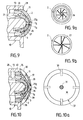
- the variant of nozzle shown in FIG. 9 includes the advantageous arrangements of FIG. 8, namely precompression of fluids thanks to the frustoconical shapes 21, 22 of the internal faces of the cups, as well as swirling movements of the fluids; according to this variant, the fins 26, 27 causing these vortex movements are all carried by the bottom of the central cup: these fins are of the type described according to FIG. 8b; the fins 26 are provided on the internal face of the central cup 2 and also visible in FIG. 9a, seen from the left of FIG. 9, and the fins 27 are provided on the external face of the central cup 2 and also visible on FIG. 9b, view from the right of FIG. 9.
- the variant of Figure 9 is also advantageous by the relative arrangement and the constitution of the central and peripheral channels.
- the central channel is conical converging outwardly 7a, and the conical peripheral channel diverge outwardly in 25 b; the two trunks of cones 7 a and 25 b are separated by a space 7 b in which the fluids meet; this venturi arrangement causes compression of the liquid to be dispensed in 7 a , the meeting of the liquid to be dispensed and the gas in 7 b , the depression of the mixture in 25 b , and promotes the fineness and homogeneity of the spraying.
- the variant nozzle according to FIG. 10, and partially FIG. 10a is similar to that of FIG. 9, to which a cap 37 in the form of a cup has been added; the cap 37 consists of a cylindrical skirt 38 and a spherical cap 39, connected by radial ribs 30.
- the skirt 38 is fitted with a seal, on the one hand, on the cylindrical outer face of the peripheral cup 11 clipped at 35 and, on the other hand, inside the external end piece 28, clipped at 40, also with sealing.
- the space between the inside face of the cap 39 and the outside face of the peripheral cup 11 defines a plurality of conical channels converging towards the outside, the outside face of the cup being provided conical according to 29 in FIG.
- the dispensing nozzle variants described with reference to FIGS. 6 to 10a apply regardless of the dispensing pump fitted to the dispenser according to the invention. They also apply to the distribution pump, also according to the present invention, in particular that described with reference to FIGS. 4 and 5.
- the pump 60 comprises a cylindrical pump body 69; at the upper end of this pump body 69 is fixed, for example by clipping, a cuff 61 which is held on the container by a cup 62, by means of a sealing washer 63.
- the push button 10 of the pump is slidably mounted along the outer wall of the cuff 61, which is in the general shape of a cap, the bottom of which is crossed, at its center, by a hollow piston rod 18, secured to the push button 10 ; the interior 19 of the hollow rod 18 communicates, via a supply inlet 9, with the central chamber 4 of the dispensing nozzle 1 carried by the push-button 10.
- the piston by its sealing lip 67 a , slides inside the body 69, and carries a cylindrical sock 67 surrounding the piston rod 18, and extending opposite the seal.
- the cuff 61 carries a cylindrical skirt 17 also surrounding the piston rod 18, but located inside the sock 67 of the piston; the end 68 of the sock 67, in the form of a lip, cooperates in sealing with the external face of the skirt, at least over an axial length of the latter.
- a first valve 76 comprises a first elongate part extending inside the piston rod 18 and bearing 76 has a conical portion for bearing on a seat 18 constituted by the rim of a short hollow cylindrical portion formed in the bore 19: a spring 71 cooperates with a second elongated part of the first valve 76 which extends outside the piston rod 18.
- a second valve 72 surrounds the second elongated portion of the first valve 76; cylindrical in shape, the second valve carries, at one end, a conical part 75 intended to cooperate with a complementary conical seat 78 carried by an enlarged part of the first valve 76, located between its two elongated parts.
- the second valve 72 is provided with a sealing surface 73 intended to cooperate, sealingly, with the external surface of a tubular sealing sleeve 74, provided in the support 69 coaxially, the outer surface of the sleeve 74 and the inner face of the support connecting to the lower end of the support 69.
- the extension of a hollow heel 70 makes it possible to connect to the support 69 a dip tube, as usual.
- FIG. 4 The container containing gas under pressure, the constituent elements of the pump are shown in FIG. 4 in the rest position, the push-button 10 not being subjected to any action.
- the spring 71 applies the first valve 76 on the seat 18 a
- the liquid under the pressure of the pressurized gas contained in the container, rises the piston-first valve-push-button assembly upwards until the end 68 of the sock 67 comes abut against the edge of the cuff 61
- additional safety and sealing surfaces are further provided on the push button and the cuff, respectively interior 10 a , and exterior 61 a
- the second valve 72 rests, by gravity, on the first turns of the spring 71 which surround the second elongated part of the first valve by projecting its outer surface, here thinned to define the support of the spring on the first valve 76; in
- the pressurized gas is retained by the cooperation of the end 68 of the sock 67 with the external face of the skirt 17: in fact, the pressurized gas is present around the body 69 and inside the cup 62, passes at 63 to the washer 63, a continuous space 64 and located at 65 between the body 69 and the cuff 61, then a passage 66 provided on the upper edge of the body 69 facing the bottom of the cuff 61.
- the lip 68 of the sock does not ensures more tightness of the gas under pressure, and this is brought to the peripheral chamber of the nozzle 1 via the circular passage 20 between the skirt 17 and the rod 18, the interior of the push button mounted at 10 a and 61 has a seal on the sleeve 61.
- the end of travel of the push button and of the elements of the pump is shown in FIG. 5.
Landscapes
- Chemical & Material Sciences (AREA)
- Dispersion Chemistry (AREA)
- Engineering & Computer Science (AREA)
- Mechanical Engineering (AREA)
- Containers And Packaging Bodies Having A Special Means To Remove Contents (AREA)
- Nozzles (AREA)
- Closures For Containers (AREA)
- Devices For Dispensing Beverages (AREA)
Applications Claiming Priority (2)
| Application Number | Priority Date | Filing Date | Title |
|---|---|---|---|
| FR9203352 | 1992-03-20 | ||
| FR929203352A FR2688714B1 (fr) | 1992-03-20 | 1992-03-20 | Distributeur de liquide equipe d'une pompe de distribution et pompe de distribution pour un tel distributeur. |
Publications (2)
| Publication Number | Publication Date |
|---|---|
| EP0561666A1 true EP0561666A1 (de) | 1993-09-22 |
| EP0561666B1 EP0561666B1 (de) | 1997-11-19 |
Family
ID=9427879
Family Applications (1)
| Application Number | Title | Priority Date | Filing Date |
|---|---|---|---|
| EP93400572A Expired - Lifetime EP0561666B1 (de) | 1992-03-20 | 1993-03-05 | Flüssigkeitspender mit einer Abgabepumpe und Abgabepumpe für einen solchen Spender |
Country Status (6)
| Country | Link |
|---|---|
| EP (1) | EP0561666B1 (de) |
| JP (1) | JPH07256161A (de) |
| CA (1) | CA2092063C (de) |
| DE (1) | DE69315243T2 (de) |
| ES (1) | ES2109446T3 (de) |
| FR (1) | FR2688714B1 (de) |
Cited By (3)
| Publication number | Priority date | Publication date | Assignee | Title |
|---|---|---|---|---|
| NL2020054B1 (en) * | 2017-12-12 | 2019-06-21 | Protix Bv | Centralized system for distributing olfactory triggers for ovipositioning to insect breeding enclosures |
| CN112718300A (zh) * | 2020-12-23 | 2021-04-30 | 伟润城生物科技(浙江)有限公司 | 一种带有液位锁定机构的组合式消毒喷雾 |
| US11382323B2 (en) | 2017-04-04 | 2022-07-12 | Protix B.V. | Centralized system for distributing olfactory triggers for ovipositioning to insect breeding enclosures |
Families Citing this family (1)
| Publication number | Priority date | Publication date | Assignee | Title |
|---|---|---|---|---|
| CN110589208A (zh) * | 2019-08-12 | 2019-12-20 | 浙江正庄实业有限公司 | 改进型泵芯及其环保高新材料制备方法 |
Citations (3)
| Publication number | Priority date | Publication date | Assignee | Title |
|---|---|---|---|---|
| EP0307310A1 (de) * | 1987-09-09 | 1989-03-15 | VALOIS Société Anonyme dite: | Zerstaüber mit Vordruck-Handpumpe für die Benutzung mit einem Treibgas |
| EP0309010A1 (de) * | 1987-07-08 | 1989-03-29 | Ing. Erich Pfeiffer GmbH & Co. KG | Handbetätigbare Austragvorrichtung für Medien |
| EP0451615A2 (de) * | 1990-04-10 | 1991-10-16 | Ing. Erich Pfeiffer GmbH & Co. KG | Austragvorrichtung für mindestens ein Medium |
-
1992
- 1992-03-20 FR FR929203352A patent/FR2688714B1/fr not_active Expired - Fee Related
-
1993
- 1993-03-05 ES ES93400572T patent/ES2109446T3/es not_active Expired - Lifetime
- 1993-03-05 DE DE69315243T patent/DE69315243T2/de not_active Expired - Fee Related
- 1993-03-05 EP EP93400572A patent/EP0561666B1/de not_active Expired - Lifetime
- 1993-03-19 CA CA002092063A patent/CA2092063C/fr not_active Expired - Fee Related
- 1993-03-22 JP JP5085154A patent/JPH07256161A/ja active Pending
Patent Citations (3)
| Publication number | Priority date | Publication date | Assignee | Title |
|---|---|---|---|---|
| EP0309010A1 (de) * | 1987-07-08 | 1989-03-29 | Ing. Erich Pfeiffer GmbH & Co. KG | Handbetätigbare Austragvorrichtung für Medien |
| EP0307310A1 (de) * | 1987-09-09 | 1989-03-15 | VALOIS Société Anonyme dite: | Zerstaüber mit Vordruck-Handpumpe für die Benutzung mit einem Treibgas |
| EP0451615A2 (de) * | 1990-04-10 | 1991-10-16 | Ing. Erich Pfeiffer GmbH & Co. KG | Austragvorrichtung für mindestens ein Medium |
Cited By (3)
| Publication number | Priority date | Publication date | Assignee | Title |
|---|---|---|---|---|
| US11382323B2 (en) | 2017-04-04 | 2022-07-12 | Protix B.V. | Centralized system for distributing olfactory triggers for ovipositioning to insect breeding enclosures |
| NL2020054B1 (en) * | 2017-12-12 | 2019-06-21 | Protix Bv | Centralized system for distributing olfactory triggers for ovipositioning to insect breeding enclosures |
| CN112718300A (zh) * | 2020-12-23 | 2021-04-30 | 伟润城生物科技(浙江)有限公司 | 一种带有液位锁定机构的组合式消毒喷雾 |
Also Published As
| Publication number | Publication date |
|---|---|
| CA2092063A1 (fr) | 1993-09-21 |
| FR2688714B1 (fr) | 1994-06-17 |
| CA2092063C (fr) | 1999-01-12 |
| EP0561666B1 (de) | 1997-11-19 |
| DE69315243D1 (de) | 1998-01-02 |
| FR2688714A1 (fr) | 1993-09-24 |
| JPH07256161A (ja) | 1995-10-09 |
| ES2109446T3 (es) | 1998-01-16 |
| DE69315243T2 (de) | 1998-03-19 |
Similar Documents
| Publication | Publication Date | Title |
|---|---|---|
| EP0734969B1 (de) | Aerosolbehälter, versehen mit zwei Sprühdüsen | |
| CA2152147C (fr) | Pompe manuelle a precompression pour la pulverisation d'un liquide et ensemble de distribution equipe d'une telle pompe | |
| CA2163483C (fr) | Pompe manuelle a precompression pour la pulverisation d'un liquide et ensemble de distribution equipe d'une telle pompe | |
| EP0747131B1 (de) | Pumpenvorrichtung zum Entnehmen einer Flüssigkeit aus einem Behälter und zu deren Zerstäubung | |
| FR2656900A1 (fr) | Pompe manuelle a precompression pour la pulverisation d'un liquide, notamment d'un parfum. | |
| CA2360883C (fr) | Dispositif de pulverisation comportant au moins deux orifices de sortie de gaz vecteur | |
| EP1606192B1 (de) | Abgabevorrichtung mit einer druckbetätigbaren pumpe | |
| EP0544549B1 (de) | Pumpe zur Förderung von einem flüssigen oder pastösen Produkt, und Ausgabebehälter mit einer solchen Pumpe | |
| EP1302246A1 (de) | Einrichtung zum Zerstäuben von mindestens eines Produktes auf einem Substrat, insbesondere auf einem Keratinsubstrat wie Haut | |
| EP0000313A1 (de) | Zerstäuberpumpe mit Druckstauwirkung und Sprühkopf | |
| EP0658490B1 (de) | Herabdrückbares Ventil zum Zerstäuben einer Flüssigkeit und mit diesem Ventil versehener Druckbehälter | |
| EP0561666B1 (de) | Flüssigkeitspender mit einer Abgabepumpe und Abgabepumpe für einen solchen Spender | |
| EP0605275B1 (de) | Anordnung zur Zerstäubung einer Flüssigkeit mit einer Vordruckpumpe | |
| EP1616632B1 (de) | Pumpe zum Ausbringen eines Produkts in verschiedenen Sprühpositionen und entsprechender Behälter | |
| EP1867396B1 (de) | Lackierspritzpistole mit Druckdose | |
| CH625019A5 (de) | ||
| EP0561696B1 (de) | Verteilungsdüse | |
| EP0499537B1 (de) | Vorrichtung zur Zerstäubung oder Abgabe eines flüssigen Produktes mit einem Schiebesteigrohr im Saugrohr | |
| FR2705323A1 (fr) | Valve de diffusion pour un récipient aérosol, et récipient aérosol équipé d'une telle valve. | |
| FR2708908A1 (fr) | Bouton-poussoir à buse de pulvérisation destiné à être monté sur un distributeur et distributeur équipé d'un tel bouton-poussoir. | |
| EP2279795B1 (de) | Austragvorrichtung für ein fluid | |
| FR2707265A1 (fr) | Dispositif de distribution de liquide, en particulier sous forme aérosol. | |
| FR2990931A1 (fr) | Systeme de distribution d'un produit fluide | |
| FR2779185A1 (fr) | Pompe pour distributeur de produits fluides et pateux |
Legal Events
| Date | Code | Title | Description |
|---|---|---|---|
| PUAI | Public reference made under article 153(3) epc to a published international application that has entered the european phase |
Free format text: ORIGINAL CODE: 0009012 |
|
| 17P | Request for examination filed |
Effective date: 19930308 |
|
| AK | Designated contracting states |
Kind code of ref document: A1 Designated state(s): DE ES FR GB IT |
|
| 17Q | First examination report despatched |
Effective date: 19950726 |
|
| GRAG | Despatch of communication of intention to grant |
Free format text: ORIGINAL CODE: EPIDOS AGRA |
|
| GRAH | Despatch of communication of intention to grant a patent |
Free format text: ORIGINAL CODE: EPIDOS IGRA |
|
| GRAH | Despatch of communication of intention to grant a patent |
Free format text: ORIGINAL CODE: EPIDOS IGRA |
|
| GRAA | (expected) grant |
Free format text: ORIGINAL CODE: 0009210 |
|
| AK | Designated contracting states |
Kind code of ref document: B1 Designated state(s): DE ES FR GB IT |
|
| ITF | It: translation for a ep patent filed | ||
| GBT | Gb: translation of ep patent filed (gb section 77(6)(a)/1977) |
Effective date: 19971119 |
|
| REF | Corresponds to: |
Ref document number: 69315243 Country of ref document: DE Date of ref document: 19980102 |
|
| REG | Reference to a national code |
Ref country code: ES Ref legal event code: FG2A Ref document number: 2109446 Country of ref document: ES Kind code of ref document: T3 |
|
| PLBE | No opposition filed within time limit |
Free format text: ORIGINAL CODE: 0009261 |
|
| STAA | Information on the status of an ep patent application or granted ep patent |
Free format text: STATUS: NO OPPOSITION FILED WITHIN TIME LIMIT |
|
| 26N | No opposition filed | ||
| PGFP | Annual fee paid to national office [announced via postgrant information from national office to epo] |
Ref country code: DE Payment date: 19991231 Year of fee payment: 8 |
|
| PGFP | Annual fee paid to national office [announced via postgrant information from national office to epo] |
Ref country code: GB Payment date: 20000301 Year of fee payment: 8 |
|
| PGFP | Annual fee paid to national office [announced via postgrant information from national office to epo] |
Ref country code: FR Payment date: 20000310 Year of fee payment: 8 |
|
| PGFP | Annual fee paid to national office [announced via postgrant information from national office to epo] |
Ref country code: ES Payment date: 20000322 Year of fee payment: 8 |
|
| PG25 | Lapsed in a contracting state [announced via postgrant information from national office to epo] |
Ref country code: GB Free format text: LAPSE BECAUSE OF NON-PAYMENT OF DUE FEES Effective date: 20010305 |
|
| PG25 | Lapsed in a contracting state [announced via postgrant information from national office to epo] |
Ref country code: ES Free format text: LAPSE BECAUSE OF NON-PAYMENT OF DUE FEES Effective date: 20010306 |
|
| GBPC | Gb: european patent ceased through non-payment of renewal fee |
Effective date: 20010305 |
|
| PG25 | Lapsed in a contracting state [announced via postgrant information from national office to epo] |
Ref country code: FR Free format text: LAPSE BECAUSE OF NON-PAYMENT OF DUE FEES Effective date: 20011130 |
|
| REG | Reference to a national code |
Ref country code: FR Ref legal event code: ST |
|
| PG25 | Lapsed in a contracting state [announced via postgrant information from national office to epo] |
Ref country code: DE Free format text: LAPSE BECAUSE OF NON-PAYMENT OF DUE FEES Effective date: 20020101 |
|
| REG | Reference to a national code |
Ref country code: ES Ref legal event code: FD2A Effective date: 20030203 |
|
| PG25 | Lapsed in a contracting state [announced via postgrant information from national office to epo] |
Ref country code: IT Free format text: LAPSE BECAUSE OF NON-PAYMENT OF DUE FEES;WARNING: LAPSES OF ITALIAN PATENTS WITH EFFECTIVE DATE BEFORE 2007 MAY HAVE OCCURRED AT ANY TIME BEFORE 2007. THE CORRECT EFFECTIVE DATE MAY BE DIFFERENT FROM THE ONE RECORDED. Effective date: 20050305 |