EP0561714A2 - Elektrizitätszähler mit Gestell aus Polycarbonat - Google Patents
Elektrizitätszähler mit Gestell aus Polycarbonat Download PDFInfo
- Publication number
- EP0561714A2 EP0561714A2 EP93400718A EP93400718A EP0561714A2 EP 0561714 A2 EP0561714 A2 EP 0561714A2 EP 93400718 A EP93400718 A EP 93400718A EP 93400718 A EP93400718 A EP 93400718A EP 0561714 A2 EP0561714 A2 EP 0561714A2
- Authority
- EP
- European Patent Office
- Prior art keywords
- base
- meter
- terminal
- flange
- cover
- Prior art date
- Legal status (The legal status is an assumption and is not a legal conclusion. Google has not performed a legal analysis and makes no representation as to the accuracy of the status listed.)
- Withdrawn
Links
Images


Classifications
-
- G—PHYSICS
- G01—MEASURING; TESTING
- G01R—MEASURING ELECTRIC VARIABLES; MEASURING MAGNETIC VARIABLES
- G01R11/00—Electromechanical arrangements for measuring time integral of electric power or current, e.g. of consumption
- G01R11/02—Constructional details
- G01R11/04—Housings; Supporting racks; Arrangements of terminals
Definitions
- This invention relates generally to electric utility revenue meters.
- Watt hour meters most commonly used as electrical energy revenue meters are the single induction electro-mechanical type. These meters have proven to have a high degree of accuracy and reliability through many years of service under varying ambient operating conditions. These meters have proven so reliable that accrediting authorities in Canada only require sample testing from which a number of meters can be sealed for a period of twelve years and this can be extended for periods of up to eight years indefinitely depending upon the accuracy criteria.
- the conventional electro-mechanical induction meter lasts in the vicinity of thirty to forty-five years.
- the basic components of the meter are assembled on a frame which is mounted on a base; a glass cover attaches to the base to form an enclosure for these basic meter components.
- the cover is sealed to the base and the cover and base are so designed that it is almost impossible to tamper with the adjustments of the meter without leaving evidence.
- the existing meter bases are made from a phenolic material, i.e. Bakelite* , and the current terminals slide through slots in the base. The terminals are held in place by a rubber gasket and metal washer on the inside and a cotter pin through the blade terminal on the outside. Assembly of this structure is labour intensive and requires a number of parts. * Trade-mark
- the current terminals project through the base so that they may mate with the terminal receptacle or meter box normally mounted on the side of the house or building.
- the terminals therefore provide the electrical connection from the utility distribution network through the meter to the house or building.
- Current is carried through a current coil and a potential coil in the meter. This induces flux in the electro-magnetic system of the meter to rotate a rotor (disk) in the meter in response to and proportional to the energy being consumed.
- an electric utility revenue meter box formed from a polycarbonate material.
- the base preferably has a knife-edge rib near its outer periphery for sealingly engaging a flange around the cup shaped glass cover of the meter.
- a metal ring for joining a cup-shaped transparent cover to a base of a watt hour meter comprising a flange directed inwardly for engaging an outside face of an outwardly directed flange on the open end of the cup-shaped transparent cover, a first plurality of tabs struck out from said ring and bendable inwardly for engaging an inside face of said cover flange and a second plurality of struck out tabs directed inwardly to engage tapered ramps adjacent an outer periphery of said meter base.
- an electro-mechanical induction meter comprising: a base having slots therein with integral locking means associated therewith; a current terminal having a blade received by one of said slots, said current terminal having a formation for locking to said locking means.
- Figure 1 is an exploded view of applicant's electro-mechanical induction watt hour meter the major components of which are a base 10, an electro-magnetic unit 20, a register and rotor unit 30 and a transparent glass cover 70.
- the electro-magnetic unit 30 has a core unit 21 with respective current and potential coils 22 and 23 mounted thereon. There are two current coils, one being visible in Figure 1, the other being located behind the visible coil 22.
- a magnetic disk brake 24 is carried by the unit 20 and has a gap 25 for receiving a portion of a rotor disk 34 which is part of the register and rotor unit 30.
- the unit 20 securely attaches to the molded base 10 and has pairs of current terminals 11a and 11b projecting therefrom. There are two current terminals for each of the two current coils.
- Base 10 is molded from a thermoplastic material in the nature of a polycarbonate material.
- the base being molded of a polycarbonate material, is rigid but at the same time displays certain flexibility allowing for constructions and designs not made possible the conventional Bakelite* base.
- the polycarbonate is preferably class fibre reinforced (roughly 10% glass fibre) and ultraviolet light stabilized.
- the preferred polycarbonate is identified as #9417 polycarbonate resin available from Bayer Company of Germany under their Trade-Mark Makrolon. The resiliency of the base is relied upon as will become more apparent hereinafter.
- the magnetic coil unit 20 snap fits onto the base by means of selected ones of a plurality of lugs 16 projecting from the base. There are also spacer and positioning lugs on the base and some of the lugs on the base cooperate with lugs projecting from the housing of the register and rotor unit 30. * Trade-mark
- the register and rotor unit 30 is a module that snap fits onto coil unit 20.
- Unit 30 includes a molded plastics (Preferably Ryton* PPS) housing 31 having a plurality of spacer lugs 32 projecting therefrom and attaching lugs 33 for precisely locating unit 30 relative to unit 20 and attaching unit 30 to the coil unit 20 mounted on the base.
- a molded plastics Preferably Ryton* PPS
- the unit 30 has a register diagrammatically illustrated by its face designated 30A and a name plate 35 that attaches to and extends downwardly from the molded plastic housing 31.
- the locating lugs 32 position the unit 30 relative to unit 20 such that, as previously mentioned, disk 34 fits into the gap 25 and lugs 33 snap fasten onto coil unit 20 (and/or base unit 10).
- the disc 34 is caused to rotate by the electro-magnetic unit 20 in a known manner.
- disk 34 is mounted on a shaft or spindle 36 having respective upper and lower bearing units 37 and 38 on the molded plastic housing unit 31.
- a pintle 39 associated with the upper bearing 37, projects therefrom into a pintle receiving unit 39A on the molded plastic housing 31.
- Worm gear 36A on the upper end of rotor shaft 36 meshes with a drive gear (not shown) for the register unit which, via dials, visually indicates the cumulative energy consumed.
- the glass cover 70 has an outwardly directed flange 71 with a seat portion 72 that abuts against a seal forming knife edge rib 14 on the base 10.
- the outwardly directed flange 71 carries a metal ring 73 provided with lugs that engage tapered ramps 76 (figure 10) on the flange 15 of the base forming a bayonet type mount whereby the glass cover and base may be rotated relative to one another to detachably join them together with the outer edge of rib 14 on the base being pressed against the seat 72 on the glass cover forming a seal.
- the inclined ramp 76 brings the base and glass cover into tight pressure engagement as one is rotated relative to the other.
- the resiliency of the material of which base 16 is made permits the forming of a tight seal between the knife edge 14A and the glass cover.
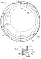
- Figure 5 is a partial cross-sectional view through an edge portion of the glass cover 70, metal ring 73 and the base 10 clearly illustrating the peripheral rib 14 as having a knife edge 14A that engages the seat 72 of the glass cover. Figure 5 also illustrates the lugs 75 projecting from ring 73.
- the metal ring 73 is illustrated in Figure 6 which in accordance with an aspect of the present invention has a first plurality of tabs 75A struck out from the ring for engaging the inside face of the outwardly directed flange 71 (see figure 5) of the glass cover and a second plurality of struck out tabs 75 for engaging the tapered ramps 76 (figure 10) of the base 10.
- the tabs 75 and 75A are spaced relative to one another in the direction of the width of the band 73.
- the metal band has an inwardly directed flange 78 for engaging the outside face of the cover flange 71 to press the flange 71 against tabs 75 (see figure 5).
- the struck out tabs 75 have free outer end portions A & B bent inwardly to provide a spring type engagement with the tapered ramp 76 (figure 10) on the base.
- Figure 4 illustrates the base 10 without spacer lugs and connecting lugs.
- the face 116 of the base 10 shown in Figure 4 is the face disposed interiorly of the meter when the base is clamped to the glass cover.
- the base is formed with four elongated slots 100 for receiving the blades of respective ones of four different blade type current terminals, one 11B of which is illustrated in figure 4 occupying one of the slots.
- Current terminal 11b has two oppositely directed wings 112 and 113. The wings 112 and 113 bear against the inside face 116 of the base 10 and keep the current terminal from sliding through the slot. This eliminates the need for washers and gaskets as is the case in the prior art.
- Figures 9 and 10 show a portion of the opposite side of base 10 from that shown in Figure 4. Thus, figures 9 and 10 show the face 117 which is disposed exteriorly of the meter.
- Figure 10 is an exploded view illustrating a slot 100 for receiving the blade 111 of a current terminal 11b.
- terminal 111 in addition to wings 112, 113, has notches 114, 115 on opposite edges of the terminal. The notches are spaced from the wings in the direction of the chamfered end 121 of the terminal.
- Formed integrally with the base 10 is a pair of fingers 118 and 119 which, adjacent their free ends, overlap respective opposite end portions of the slot 100.
- the fingers 118 and 119 merge into the rest of the base as indicated at 120 and forwardly thereof the fingers are free to move relative to the base.
- the leading end of the terminal 11b is chamfered at 121 and when the terminal is inserted into the slot, the terminal causes the arms 118 and 119 to flex outwardly.
- the terminal is pushed through to a position where the wings 112 and 113 of the terminal engage the inner face 116 (figure 4) of the base, the fingers 118 and 119 snap into respective slots 114 and 115 of the terminal.
- Figure 9 illustrates the terminal 11 in its final position with the fingers 118 and 119 seated in the respective slots 114 and 115.
- the resiliency of the polycarbonate material from which the base 10 is made allows forming a seal integrally with the base eliminating the need of a separate O-ring as has been the common practice.
- the plastics for the molded housing, pilot bearings and meter base are engineering grade resins and preferably rigid thermoplastic materials such as those identified hereinbefore.
Landscapes
- Physics & Mathematics (AREA)
- General Physics & Mathematics (AREA)
- Measuring Volume Flow (AREA)
- Connection Of Plates (AREA)
- Connector Housings Or Holding Contact Members (AREA)
Applications Claiming Priority (2)
| Application Number | Priority Date | Filing Date | Title |
|---|---|---|---|
| CA2063618 | 1992-03-20 | ||
| CA002063618A CA2063618C (en) | 1992-03-20 | 1992-03-20 | Electric utility revenue meter polycarbonate base |
Publications (2)
| Publication Number | Publication Date |
|---|---|
| EP0561714A2 true EP0561714A2 (de) | 1993-09-22 |
| EP0561714A3 EP0561714A3 (en) | 1994-05-11 |
Family
ID=4149474
Family Applications (1)
| Application Number | Title | Priority Date | Filing Date |
|---|---|---|---|
| EP19930400718 Withdrawn EP0561714A3 (en) | 1992-03-20 | 1993-03-22 | Electric utility revenue meter polycarbonate base |
Country Status (4)
| Country | Link |
|---|---|
| US (1) | US5364290A (de) |
| EP (1) | EP0561714A3 (de) |
| BR (1) | BR9301259A (de) |
| CA (3) | CA2063618C (de) |
Cited By (3)
| Publication number | Priority date | Publication date | Assignee | Title |
|---|---|---|---|---|
| EP1155332A4 (de) * | 1998-12-01 | 2005-05-18 | Schlumberger Resource Man Serv | Modulare zaehleranordnung und verfahren zu deren verwendung |
| WO2015174816A1 (es) * | 2014-05-12 | 2015-11-19 | Garza Leal Jesus | Carcasa protectora de lector de energia electrica con lente de cristal |
| WO2018202517A1 (en) * | 2017-05-05 | 2018-11-08 | Cavagna Group S.P.A. | A station |
Families Citing this family (22)
| Publication number | Priority date | Publication date | Assignee | Title |
|---|---|---|---|---|
| US5473504A (en) * | 1994-12-27 | 1995-12-05 | General Electric Company | Electric meter with desired seating torque |
| US5956223A (en) * | 1997-01-15 | 1999-09-21 | Cooper Industries, Inc. | Surge protection system including proper operation indicator |
| US6615147B1 (en) * | 1999-08-09 | 2003-09-02 | Power Measurement Ltd. | Revenue meter with power quality features |
| US6493644B1 (en) * | 1999-08-09 | 2002-12-10 | Power Measurement Ltd. | A-base revenue meter with power quality features |
| US6386790B1 (en) * | 2000-07-26 | 2002-05-14 | Abb Automation Inc. | One-piece stainless steel rim for mating a meter cover and base and method of making same |
| DE10194663D2 (de) * | 2000-10-28 | 2003-10-02 | Bosch Gmbh Robert | Vorrichtung zum lösbaren, gelenkigen Verbinden eines Wischblatts zum Reinigen von Scheiben mit einem Wischerarm |
| DE10101521A1 (de) * | 2001-01-12 | 2002-07-18 | Bosch Gmbh Robert | Getriebe-Antriebseinheit |
| US6605937B2 (en) | 2001-06-01 | 2003-08-12 | General Electric Company | Modular meter with base barrier |
| US7274553B2 (en) * | 2003-02-03 | 2007-09-25 | Landis+Gyr Inc. | Utility meter housing arrangement |
| US7530315B2 (en) | 2003-05-08 | 2009-05-12 | Lone Star Ip Holdings, Lp | Weapon and weapon system employing the same |
| US7154041B2 (en) * | 2004-05-05 | 2006-12-26 | Itron, Inc. | Double wall isolated remote electronic enclosure apparatus |
| US20070194899A1 (en) * | 2004-07-27 | 2007-08-23 | Tenitek Ltd. | Indicator For A Control Wheel |
| US8117955B2 (en) * | 2006-10-26 | 2012-02-21 | Lone Star Ip Holdings, Lp | Weapon interface system and delivery platform employing the same |
| US7973673B2 (en) * | 2007-04-02 | 2011-07-05 | Itron, Inc. | Automated meter reader direct mount endpoint module |
| US7821776B2 (en) * | 2008-03-25 | 2010-10-26 | Elster Electricity, Llc | Tamper resistant meter assembly |
| US8717007B2 (en) * | 2008-10-10 | 2014-05-06 | Electro Industries/Gauge Tech | Intelligent electronic device having a terminal assembly for coupling to a meter mounting socket |
| US8218295B1 (en) * | 2010-02-10 | 2012-07-10 | Shoemaker Mark K | Universal meter mounting block, unitary lug, sliding lug cap and meter mounting enclosure therefor |
| US8339223B1 (en) * | 2011-08-19 | 2012-12-25 | General Electric Company | Electric solenoid for a meter disconnect relay |
| US10048088B2 (en) | 2015-02-27 | 2018-08-14 | Electro Industries/Gauge Tech | Wireless intelligent electronic device |
| US11009922B2 (en) | 2015-02-27 | 2021-05-18 | Electro Industries/Gaugetech | Wireless intelligent electronic device |
| US9897461B2 (en) | 2015-02-27 | 2018-02-20 | Electro Industries/Gauge Tech | Intelligent electronic device with expandable functionality |
| US9921245B2 (en) * | 2015-07-01 | 2018-03-20 | Honeywell International Inc. | Electricity meter forms module |
Family Cites Families (16)
| Publication number | Priority date | Publication date | Assignee | Title |
|---|---|---|---|---|
| US1664672A (en) * | 1926-03-12 | 1928-04-03 | Duncan Electric Mfg Co | Induction electricity meter |
| US2790951A (en) * | 1951-05-22 | 1957-04-30 | Sangamo Electric Co | Hermetically sealed watthour meters |
| US3355630A (en) * | 1965-09-30 | 1967-11-28 | Basic Products Corp | Meter structure with imbedded bus bars and jaw mounting structure |
| US3846677A (en) * | 1972-06-07 | 1974-11-05 | Westinghouse Electric Corp | Plastic watthour meter cover having an indexed and protected front face |
| US3943413A (en) * | 1974-07-03 | 1976-03-09 | Westinghouse Electric Corporation | Tamperproof external test contact arrangement for watthour meters |
| US4162116A (en) * | 1974-07-29 | 1979-07-24 | Wasagchemie Gmbh | Detachable, water-tight connection elements for detonating devices and components which process for the ignition signal |
| US3997236A (en) * | 1975-03-03 | 1976-12-14 | Motorola, Inc. | Self-locking electrical contact assembly |
| CH595638A5 (en) * | 1975-10-31 | 1978-02-15 | Landis & Gyr Ag | Polycarbonate transparent electronic power meter housing |
| US4068288A (en) * | 1976-05-12 | 1978-01-10 | Westinghouse Electric Corporation | Tamper proof watthour meter enclosure having a permanent locking arrangement |
| US4195901A (en) * | 1977-11-04 | 1980-04-01 | Amerace Corporation | Electrical device with terminal retainer |
| US4419554A (en) * | 1981-11-16 | 1983-12-06 | Mcgill Manufacturing Company, Inc. | Electric switches for receiving unitary internal contact/wire terminal elements |
| US4645286A (en) * | 1983-02-10 | 1987-02-24 | Elliot Isban | Quick connect power tap system |
| US4762507A (en) * | 1987-04-24 | 1988-08-09 | Amp Incorporated | Electrical contact retention system, and tool for removal and method therefor |
| US4744004A (en) * | 1987-05-27 | 1988-05-10 | Transdata, Inc. | Electricity meter with solid-state circuits |
| US4857007A (en) * | 1988-07-01 | 1989-08-15 | Molex Incorporated | Molded environmental seal for electrical connection |
| US5057767A (en) * | 1990-04-05 | 1991-10-15 | General Electric Company | Optical communications light shield for energy meter |
-
1992
- 1992-03-20 CA CA002063618A patent/CA2063618C/en not_active Expired - Fee Related
- 1992-03-20 CA CA002315936A patent/CA2315936A1/en not_active Abandoned
- 1992-03-20 CA CA002315934A patent/CA2315934C/en not_active Expired - Fee Related
-
1993
- 1993-03-18 US US08/033,945 patent/US5364290A/en not_active Expired - Lifetime
- 1993-03-22 BR BR9301259A patent/BR9301259A/pt not_active Application Discontinuation
- 1993-03-22 EP EP19930400718 patent/EP0561714A3/en not_active Withdrawn
Cited By (8)
| Publication number | Priority date | Publication date | Assignee | Title |
|---|---|---|---|---|
| EP1155332A4 (de) * | 1998-12-01 | 2005-05-18 | Schlumberger Resource Man Serv | Modulare zaehleranordnung und verfahren zu deren verwendung |
| US7701199B2 (en) | 1998-12-01 | 2010-04-20 | Itron, Inc. | Modular meter configuration and methodology |
| WO2015174816A1 (es) * | 2014-05-12 | 2015-11-19 | Garza Leal Jesus | Carcasa protectora de lector de energia electrica con lente de cristal |
| US10264692B2 (en) | 2014-05-12 | 2019-04-16 | Jesus Garza Leal | Protective casing for an electrical energy reader including a glass lens |
| WO2018202517A1 (en) * | 2017-05-05 | 2018-11-08 | Cavagna Group S.P.A. | A station |
| CN110651152A (zh) * | 2017-05-05 | 2020-01-03 | 卡瓦尼亚集团股份公司 | 一种站 |
| US11867361B2 (en) | 2017-05-05 | 2024-01-09 | Cavagna Group S.P.A. | Station |
| US12152738B2 (en) | 2017-05-05 | 2024-11-26 | Cavagna Group S.P.A. | Station |
Also Published As
| Publication number | Publication date |
|---|---|
| CA2063618A1 (en) | 1993-09-21 |
| BR9301259A (pt) | 1993-09-28 |
| EP0561714A3 (en) | 1994-05-11 |
| CA2315936A1 (en) | 1993-09-21 |
| CA2063618C (en) | 2000-12-05 |
| US5364290A (en) | 1994-11-15 |
| CA2315934A1 (en) | 1993-09-21 |
| CA2315934C (en) | 2001-11-06 |
Similar Documents
| Publication | Publication Date | Title |
|---|---|---|
| EP0561714A2 (de) | Elektrizitätszähler mit Gestell aus Polycarbonat | |
| US4998102A (en) | Integrated meter transponder | |
| US8334787B2 (en) | Gas meter having ultra-sensitive magnetic material retrofitted onto meter dial and method for performing meter retrofit | |
| US5342995A (en) | Protective cover system for electrical receptacles | |
| US5001420A (en) | Modular construction for electronic energy meter | |
| US1969499A (en) | Universal detachable watthour meter mounting | |
| US20080238711A1 (en) | Automated meter reader direct mount endpoint module | |
| US5027056A (en) | Multifunction register enclosure for energy meter | |
| EP0378679A4 (en) | Circuit breaker auxiliary device snap-on package | |
| CA1116735A (en) | Device for securing an apparatus in a wall | |
| US20230251288A1 (en) | Securing Apparatus and Method | |
| EP0404851A1 (de) | Elektronisches gerät | |
| CA2063620C (en) | Induction watt hour meter non-intrusive and concealed pulse initiator | |
| US4080570A (en) | Panel mounting for electrical device | |
| US4416478A (en) | Tamper deterent seal providing indication of tampering for watthour meters | |
| GB2296090A (en) | Commodity consumption meters | |
| AU751400B2 (en) | Improvements in, or relating to, electricity consumption meters | |
| US10598699B2 (en) | Securing apparatus and method | |
| EP0717286A2 (de) | Verbrauchsmessgerät | |
| US3638119A (en) | Index mountings for electrical meters | |
| CA2063617C (en) | Induction watt hour meter rotary disc mounting and bearing system | |
| US5174238A (en) | Pointer shaft in indicating instrument | |
| US3997840A (en) | Panel meter with adapter cover | |
| EP0218516A1 (de) | Aufschnappanordnung für Sichtscheibe | |
| CA1241062A (en) | Spring loaded installation for electronic register module |
Legal Events
| Date | Code | Title | Description |
|---|---|---|---|
| PUAI | Public reference made under article 153(3) epc to a published international application that has entered the european phase |
Free format text: ORIGINAL CODE: 0009012 |
|
| AK | Designated contracting states |
Kind code of ref document: A2 Designated state(s): AT CH DE ES FR GB IT LI PT |
|
| PUAL | Search report despatched |
Free format text: ORIGINAL CODE: 0009013 |
|
| AK | Designated contracting states |
Kind code of ref document: A3 Designated state(s): AT CH DE ES FR GB IT LI PT |
|
| 17P | Request for examination filed |
Effective date: 19940903 |
|
| 17Q | First examination report despatched |
Effective date: 19970505 |
|
| STAA | Information on the status of an ep patent application or granted ep patent |
Free format text: STATUS: THE APPLICATION IS DEEMED TO BE WITHDRAWN |
|
| 18D | Application deemed to be withdrawn |
Effective date: 19970916 |