EP0561826B1 - Carrosserie pour voiture de tourisme - Google Patents
Carrosserie pour voiture de tourisme Download PDFInfo
- Publication number
- EP0561826B1 EP0561826B1 EP91920524A EP91920524A EP0561826B1 EP 0561826 B1 EP0561826 B1 EP 0561826B1 EP 91920524 A EP91920524 A EP 91920524A EP 91920524 A EP91920524 A EP 91920524A EP 0561826 B1 EP0561826 B1 EP 0561826B1
- Authority
- EP
- European Patent Office
- Prior art keywords
- wing
- cross
- section
- vehicle
- post
- Prior art date
- Legal status (The legal status is an assumption and is not a legal conclusion. Google has not performed a legal analysis and makes no representation as to the accuracy of the status listed.)
- Expired - Lifetime
Links
Images
Classifications
-
- B—PERFORMING OPERATIONS; TRANSPORTING
- B62—LAND VEHICLES FOR TRAVELLING OTHERWISE THAN ON RAILS
- B62D—MOTOR VEHICLES; TRAILERS
- B62D25/00—Superstructure or monocoque structure sub-units; Parts or details thereof not otherwise provided for
- B62D25/08—Front or rear portions
- B62D25/082—Engine compartments
-
- B—PERFORMING OPERATIONS; TRANSPORTING
- B62—LAND VEHICLES FOR TRAVELLING OTHERWISE THAN ON RAILS
- B62D—MOTOR VEHICLES; TRAILERS
- B62D29/00—Superstructures, understructures, or sub-units thereof, characterised by the material thereof
- B62D29/008—Superstructures, understructures, or sub-units thereof, characterised by the material thereof predominantly of light alloys, e.g. extruded
Definitions
- the invention relates to a passenger car body according to the preamble of claim 1.
- fender For attachment of a fender, it is known to attach a fender bank pointing from a central region of a post A to the front of the vehicle.
- a fender bench usually consists of two deep-drawn and interconnected metal sheets, which form a closed, but not constant longitudinal cross-section and in most cases only consist of a folded sheet metal in the front area.
- the steel sheets used to build such bodies are deformed using the deep-drawing process.
- the pressing tools for deforming the sheets are relatively expensive, but allow very large quantities, so that an inexpensive solution is therefore available for large-scale production.
- the process described for small series is very cost-intensive.
- the known design of a fender bench with sheet metal parts can be improved in terms of rigidity and crash behavior.
- a node element lies on the post A between a front roof post and a front door post.
- One end of this node element receives the front roof pillar and the front door pillar as well as a front cross member and a fender bench facing the front of the vehicle.
- the front roof mullion, the front door mullion, the front cross member and the fender bench are designed as light metal extrusions.
- the fender bench here has only a simple, approximately square cross section.
- a wheel house with shock absorber mount is connected as a welded group of sheet metal parts to the front door jamb and to the fender bench.
- JP-A-2 175 385 In connection with a conventional sheet metal body without extruded light metal profiles, it is known (JP-A-2 175 385) to adapt a fender bank, at least in part of the profile cross section lying towards the outside of the vehicle, to the cross-sectional shape of a fender connected thereto, in such a way that the profile cross section of the Fender bench is L-shaped.
- a first, rectangular hollow chamber area lying approximately horizontally to the center of the vehicle is connected as a horizontal L-leg to a second, approximately perpendicular hollow chamber area as a vertical L-leg.
- the object of the invention is to develop a generic support structure of a passenger car body in the area of the fender seat so that an improvement in the rigidity is achieved with improved use of space.
- the fender bench is adapted by the claimed L-structure with its profile cross-section to the cross-sectional shape of a fender connected to it.
- the space below the fender is thus used to enlarge the cross-section of the extruded fender bench profile and thus to increase the rigidity.
- a wheel arch support is attached as a light metal extrusion profile at a distance from the node element between the fender seat and the front door jamb, the length of the wheel arch support and its oblique course being dimensioned such that the maximum available space is used for a vehicle tire to get the broadest possible base for a support.
- the end of the wheel arch girder is firmly connected to the fender bench and the door jamb, so that a stable, triangular girder assembly is formed as a support triangle.
- the fender bench is thereby supported downwards towards the door jamb, whereby in the event of a frontal impact, a favorable introduction of force and distribution of the impact energy is achieved.
- such a profile design results in a favorable arrangement and fastening option for a fender, which bears against the top of the first hollow chamber region with an edge flange and is connected there with screws.
- the fender then follows the edge region with its cross-sectional contour of the shape of the second hollow chamber region.
- the space under the fender is optimally used for the shape of the fender bench profile.
- an angular region is formed above the first hollow chamber region, into which a bonnet can be inserted with its edge and corresponding to its thickness, flush with the outer contour of the fender.
- the fender bank In order to further increase the rigidity of the fender bank, it can be advantageous, depending on the circumstances, to design the fender bank as a multi-chamber hollow profile, the hollow chamber regions being separated by webs. Stability adjustments are also across different wall thicknesses possible.
- an approximately square profile cross-section has proven to be expedient, the width of the profile being matched to the width of the fender seat and the door jamb.
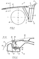
- Fig. 1 the front region of a support structure of the vehicle body 1 of a passenger car is shown, with the training in the area of the post A and the wheel house.
- the support structure consists of a node element 3 between a front roof post 4 and a front, approximately vertical door post 5.
- the roof post 4 and the door post 5 are each connected to the node element 3 at one end.
- two further beams are connected to the node element 3, of which a (not visible) cross beam as the underside of the front window extends into the plane of the drawing and a beam as a fender bench 6 points to the front of the vehicle.
- the roof post 4, the door post 5, the cross member and the fender bank 6 are Hollow profiles as extruded aluminum profiles.
- the node element 3 is an aluminum casting.
- the carrier parts thus have a closed, constant cross section over the entire length.
- the fender bench 6 is made in one piece with the existing rigidity over the entire length, which has a positive effect on the crash behavior, since this carrier can then absorb impact energy from the start. Due to the high rigidity, there are stable attachment and fastening options for auxiliary units and containers, which can also be molded onto the profile as edge webs.
- Another support is arranged as a wheel arch support 7 at a distance from the node element 3 between the fender seat 6 and the front door jamb 5 and there connected to its end sides by welding.
- the length of the wheel arch carrier 7 and its oblique course are evidently dimensioned such that the maximum available space is used towards a vehicle tire 8. This creates a large support triangle and an overall stable arrangement.
- FIG. 2 shows a cross section through the fender bank 6, to which a fender 9 is already screwed on and where the position of an engine hood 10 can be seen.
- the fender bank 6 has an L-shaped profile cross section.
- a first, lower L-leg consists of a first, rectangular hollow chamber region 11 lying approximately horizontally towards the center of the vehicle.
- a second L-leg consists of a second, rectangular hollow chamber region 12 standing approximately vertically and lying towards the outside of the vehicle.
- the two hollow chamber regions 11 and 12 can optionally be separated by a web 13 to increase the rigidity.
- the fender 9 has an edge flange 14 with which it rests on the top of the first hollow chamber region 11 and is fastened there with screw connections 15.
- the fender 9 is bent upwards with an approximately vertical wall 16 and then engages around the second hollow chamber region 12.
- the region 17 under the upper part of the fender 9 is thus used for a large and L-shaped cross section of the fender bank 6 .
- the bonnet 10 lies with its longitudinal edge and in accordance with its thickness such that the outer contour of the fender 9 and the bonnet 10 merge continuously into one another.
Landscapes
- Engineering & Computer Science (AREA)
- Chemical & Material Sciences (AREA)
- Combustion & Propulsion (AREA)
- Transportation (AREA)
- Mechanical Engineering (AREA)
- Architecture (AREA)
- Structural Engineering (AREA)
- Body Structure For Vehicles (AREA)
Abstract
Claims (4)
- Carrosserie de voiture particulière,
comprenant une structure porteuse en profilés creux qui sont assemblés par des éléments de jonction,
les profilés creux étant réalisés sous forme de profilés filés en métal léger et les éléments de jonction sous forme de pièces en fonte de métal léger,
un élément de jonction étant disposé sur le pilier A entre un pilier avant de toit et un montant avant de porte, pour recevoir et maintenir, par une extrémité de chacun d'entre eux, le pilier avant de toit et le montant avant de porte, ainsi qu'une traverse avant et un support d'aile dirigé vers le côté avant de la voiture, et
le support d'aile étant un profilé filé en métal léger,
caractérisé en ce que
le support d'aile (6) est adapté, au moins dans une partie de la section du profilé située vers le côté extérieur de la voiture, à la forme en coupe transversale d'une aile (9) qui y est fixée, si bien que la section du profilé du support d'aile (6) est en forme de L avec, en tant que branche horizontale du L, une première région (11) constituant une chambre creuse rectangulaire, à peu près horizontale et dirigée vers le milieu de la voiture, et, en tant que hranche verticale du L, une seconde région (12) constituant une chambre creuse rectangulaire, à peu prés verticale, située vers le côté extérieur de la voiture et adaptée à la forme en coupe transversale de l'aile (9), ce qui fait que la place disponible au-dessous de l'aile (9) est ainsi utilisée pour un agrandissement de la section du profilé du support d'aile et, par suite, pour une augmentation de la rigidité,
un support (7) pour carter de roue, sous forme de profilé filé en métal léger, s'étend chaque fois, à distance de l'élément de jonction (3), entre le support d'aile (6) et le montant avant de porte (5), la longueur du support (7) du carter de roue et son inclinaison étant dimensionnées de telle sorte que la place maximale disponible, à côté d'un pneu (8) de la voiture, soit utilisée pour obtenir une base aussi large que possible pour un appui, et
le support (7) du carter de roue est fixé rigidement, par ses faces d'extrémité, au support d'aile (6) et au montant avant de porte (5), de sorte qu'il est formé, en tant que triangle d'appui, une poutre composite triangulaire stable, grâce à quoi le support d'aile (6) est étayé vers le bas sur le montant avant de porte et une canalisation favorable des efforts et une répartition de l'énergie d'impact sont obtenues en cas de collision frontale. - Carrosserie de voiture particulière selon la revendication 1, caractérisée en ce que l'aile (9) est appliquée, par une bride (14) de son bord, sur le côté supérieur de la première région (11) constituant une chambre creuse et y est fixée par des vis (15),
à la suite de la bride (14) de son bord, l'aile (9) suit, par le profil de sa section, la forme de la seconde région (12) constituant une chambre creuse, et
un capot (10) est placé, par son bord longitudinal, dans la région en L (18) entre la première (11) et la seconde (12) régions constituant des chambres creuses. - Carrosserie de voiture particulière selon la revendication 2, caractérisée en ce que le support d'aile (6) est réalisé sous forme de profilé creux à compartiments multiples, les régions (11, 12) constituant des compartiments creux étant séparées par des cloisons (13).
- Carrosserie de voiture particulière selon l'une quelconque des revendications 1 à 3, caractérisée en ce que le support (7) du carter de roue a une section transversale à peu près carrée.
Applications Claiming Priority (3)
| Application Number | Priority Date | Filing Date | Title |
|---|---|---|---|
| DE4040951 | 1990-12-20 | ||
| DE4040951 | 1990-12-20 | ||
| PCT/EP1991/002230 WO1992011161A1 (fr) | 1990-12-20 | 1991-11-26 | Carrosserie pour voiture de tourisme |
Publications (2)
| Publication Number | Publication Date |
|---|---|
| EP0561826A1 EP0561826A1 (fr) | 1993-09-29 |
| EP0561826B1 true EP0561826B1 (fr) | 1994-08-10 |
Family
ID=6420893
Family Applications (1)
| Application Number | Title | Priority Date | Filing Date |
|---|---|---|---|
| EP91920524A Expired - Lifetime EP0561826B1 (fr) | 1990-12-20 | 1991-11-26 | Carrosserie pour voiture de tourisme |
Country Status (6)
| Country | Link |
|---|---|
| US (1) | US5466035A (fr) |
| EP (1) | EP0561826B1 (fr) |
| JP (1) | JP2988725B2 (fr) |
| DE (1) | DE59102528D1 (fr) |
| ES (1) | ES2062826T3 (fr) |
| WO (1) | WO1992011161A1 (fr) |
Families Citing this family (21)
| Publication number | Priority date | Publication date | Assignee | Title |
|---|---|---|---|---|
| DE19534290C2 (de) * | 1995-09-15 | 1997-02-06 | Audi Ag | Verbindung zwischen einem Strangpreßprofil und einem daran angeschlossenen flächigen Bauteil an einer Fahrzeugkarosserie |
| US6250711B1 (en) | 1998-07-31 | 2001-06-26 | Toyota Jidosha Kabushiki Kaisha | Energy absorber securing structure and method |
| DE19926352B4 (de) * | 1999-06-10 | 2004-02-12 | Daimlerchrysler Ag | Rohbaukarosserie eines Kraftfahrzeugs |
| DE19959892A1 (de) * | 1999-12-11 | 2001-06-13 | Opel Adam Ag | Vorderbau für ein Kraftfahrzeug |
| FR2800694B1 (fr) | 1999-11-05 | 2001-12-07 | Renault | Support de train arriere de vehicule automobile |
| DE19959606A1 (de) * | 1999-12-10 | 2001-06-13 | Volkswagen Ag | Fahrzeugseitenblech mit aufprallweicher Außenkante |
| AU2003204369B2 (en) * | 2000-03-31 | 2005-01-27 | Toyota Jidosha Kabushiki Kaisha | Vehicle Fender Structure |
| KR100417942B1 (ko) * | 2000-03-31 | 2004-02-11 | 도요타지도샤가부시키가이샤 | 차량의 펜더 구조 |
| JP4762438B2 (ja) * | 2001-05-18 | 2011-08-31 | 富士重工業株式会社 | 車両の前部車体構造 |
| KR100412838B1 (ko) * | 2001-07-21 | 2003-12-31 | 현대자동차주식회사 | 자동차의 휀더부 구조 |
| JP3838125B2 (ja) * | 2002-03-15 | 2006-10-25 | 日産自動車株式会社 | フェンダ構造 |
| DE10301183A1 (de) * | 2003-01-15 | 2004-07-29 | Bayerische Motoren Werke Ag | Stützträger für einen Kotflügel |
| KR20040106781A (ko) * | 2003-06-11 | 2004-12-18 | 현대자동차주식회사 | 휀더 마운팅부의 다단 충격 흡수 구조 |
| US7210733B2 (en) * | 2004-04-22 | 2007-05-01 | Ford Global Technologies, Llc | Tubular support for shock tower in automobiles |
| DE502004006139D1 (de) * | 2004-11-03 | 2008-03-20 | Ford Global Tech Llc | Karosserievorderbau für ein Kraftfahrzeug |
| FR2902741A3 (fr) | 2006-06-22 | 2007-12-28 | Renault Sas | Element de structure de vehicule automobile |
| US7469955B2 (en) * | 2007-05-29 | 2008-12-30 | Gm Global Technology Operations, Inc. | Rotatably-mountable bumper and method for cushioning contact between a vehicle hood and grill |
| EP2143623B1 (fr) * | 2008-07-12 | 2016-08-10 | AluTeam Fahrzeugtechnik GmbH | Liaison, en particulier pour pièces de constructions de véhicule |
| US7988217B2 (en) * | 2008-11-25 | 2011-08-02 | Toyota Motor Engineering & Manufacturing North America, Inc. | Hatchback door water management brackets |
| DE202009017786U1 (de) * | 2009-09-17 | 2010-06-17 | GM Global Technology Operations, Inc., Detroit | Karosserie für ein Kraftfahrzeug |
| US9694856B1 (en) * | 2015-12-18 | 2017-07-04 | Ford Global Technologies, Llc | System for attaching vehicle fenders to a common front end structure |
Family Cites Families (13)
| Publication number | Priority date | Publication date | Assignee | Title |
|---|---|---|---|---|
| DE2713604A1 (de) * | 1977-03-28 | 1978-10-05 | Volkswagenwerk Ag | Stossdaempferaufnahmen enthaltender vorderwagen eines kraftfahrzeugs |
| JPS5911464B2 (ja) * | 1978-11-10 | 1984-03-15 | 日産自動車株式会社 | 自動車の車体構造 |
| JPS5839965Y2 (ja) * | 1979-03-01 | 1983-09-08 | 日産自動車株式会社 | 自動車のフエンダ構造 |
| US4267895A (en) * | 1979-05-10 | 1981-05-19 | The Budd Company | Automotive body frame for a combined engine and battery operated vehicle |
| DE2934060A1 (de) * | 1979-08-23 | 1981-03-26 | Daimler-Benz Aktiengesellschaft, 70567 Stuttgart | Kraftfahrzeug, insbesondere personenkraftwagen, mit nachgiebigen karosseriefrontteilen |
| JPS5861075A (ja) * | 1981-10-08 | 1983-04-11 | Nissan Motor Co Ltd | エンジンル−ムのスプラツシユ浸入防止構造 |
| JPS58164415A (ja) * | 1982-03-23 | 1983-09-29 | Toyota Motor Corp | 自動車の外気導入構造 |
| JPS59190060A (ja) * | 1983-04-13 | 1984-10-27 | Honda Motor Co Ltd | 自動車の車体 |
| DE3346986A1 (de) * | 1983-12-24 | 1985-07-18 | Fleck, Andreas, 2000 Hamburg | Wagenkasten |
| US4826238A (en) * | 1986-12-01 | 1989-05-02 | Honda Giken Kogyo Kabushiki Kaisha | Side sill for automotive vehicle |
| JPH0764278B2 (ja) * | 1988-07-30 | 1995-07-12 | マツダ株式会社 | 自動車の前部車体構造 |
| JP2595703B2 (ja) * | 1988-12-27 | 1997-04-02 | 日産自動車株式会社 | 自動車の前部車体構造 |
| JPH02249773A (ja) * | 1989-03-24 | 1990-10-05 | Suzuki Motor Co Ltd | 自動車の車体構造 |
-
1991
- 1991-11-26 WO PCT/EP1991/002230 patent/WO1992011161A1/fr not_active Ceased
- 1991-11-26 JP JP4500322A patent/JP2988725B2/ja not_active Expired - Fee Related
- 1991-11-26 EP EP91920524A patent/EP0561826B1/fr not_active Expired - Lifetime
- 1991-11-26 US US08/078,199 patent/US5466035A/en not_active Expired - Fee Related
- 1991-11-26 ES ES91920524T patent/ES2062826T3/es not_active Expired - Lifetime
- 1991-11-26 DE DE59102528T patent/DE59102528D1/de not_active Expired - Fee Related
Also Published As
| Publication number | Publication date |
|---|---|
| WO1992011161A1 (fr) | 1992-07-09 |
| JPH06503780A (ja) | 1994-04-28 |
| EP0561826A1 (fr) | 1993-09-29 |
| JP2988725B2 (ja) | 1999-12-13 |
| ES2062826T3 (es) | 1994-12-16 |
| US5466035A (en) | 1995-11-14 |
| DE59102528D1 (de) | 1994-09-15 |
Similar Documents
| Publication | Publication Date | Title |
|---|---|---|
| EP0561826B1 (fr) | Carrosserie pour voiture de tourisme | |
| EP0561837B1 (fr) | Structure porteuse d'une carrosserie de vehicule de tourisme | |
| EP0461345B1 (fr) | Carrosserie pour un véhicule automobile, en particulier pour une voiture de tourisme | |
| DE19917177B4 (de) | Tragstruktur für Kraftwagen | |
| EP0461346B1 (fr) | Montant pour une structure de carrosserie de véhicule | |
| EP2547574B1 (fr) | Élément avant d'un véhicule | |
| EP0452548A2 (fr) | Poutre pour chassis de véhicule automobile | |
| WO1992011158A1 (fr) | Colonne centrale d'une carrosserie de vehicule de tourisme | |
| DE1630211B2 (de) | Selbsttragende karosserie fuer personenkraftwagen | |
| DE10239990A1 (de) | Kraftwagen-Karosserie mit einer Tragstruktur aus großformatigen Teilmodulen | |
| EP0989052B1 (fr) | Renforcement pour carosserie auto-porteuse d'un véhicule | |
| DE19737740A1 (de) | Selbsttragende Karosserie für ein Fahrzeug | |
| DE8815885U1 (de) | Fahrzeugkarosserie | |
| EP0517867B1 (fr) | Structure porteuse d'une carrosserie de vehicule de tourisme | |
| EP3959117A1 (fr) | Structure d'avant-corps de la carrosserie d'un véhicule | |
| DE19853338B4 (de) | Anordnung mit einer Frontsäule für einen Karosserierahmen eines Kraftfahrzeugs | |
| EP1199246B1 (fr) | Toit de véhicule | |
| EP0561852B1 (fr) | Assemblage de supports d'une carrosserie de vehicule | |
| DE10239991A1 (de) | Karosserie für einen Kraftwagen mit einer Dachsäule | |
| DE60024829T2 (de) | Profil für eine Karosserie | |
| EP0580605B1 (fr) | Structure portante d'une carrosserie de voiture particuliere | |
| DE10032663B4 (de) | Kraftwagen mit einer selbsttragenden Karosserie | |
| DE4138392A1 (de) | Fahrzeugkarosserie fuer einen personenkraftwagen | |
| DE4138395A1 (de) | Tragstruktur einer karosserie eines personenkraftwagens | |
| DE10260530B4 (de) | Verfahren zur Herstellung eines einstückigen Verstärkungsbleches |
Legal Events
| Date | Code | Title | Description |
|---|---|---|---|
| PUAI | Public reference made under article 153(3) epc to a published international application that has entered the european phase |
Free format text: ORIGINAL CODE: 0009012 |
|
| 17P | Request for examination filed |
Effective date: 19930416 |
|
| AK | Designated contracting states |
Kind code of ref document: A1 Designated state(s): DE ES FR GB IT |
|
| 17Q | First examination report despatched |
Effective date: 19931102 |
|
| ITF | It: translation for a ep patent filed | ||
| GRAA | (expected) grant |
Free format text: ORIGINAL CODE: 0009210 |
|
| AK | Designated contracting states |
Kind code of ref document: B1 Designated state(s): DE ES FR GB IT |
|
| REF | Corresponds to: |
Ref document number: 59102528 Country of ref document: DE Date of ref document: 19940915 |
|
| GBT | Gb: translation of ep patent filed (gb section 77(6)(a)/1977) |
Effective date: 19940920 |
|
| ET | Fr: translation filed | ||
| REG | Reference to a national code |
Ref country code: ES Ref legal event code: FG2A Ref document number: 2062826 Country of ref document: ES Kind code of ref document: T3 |
|
| PLBE | No opposition filed within time limit |
Free format text: ORIGINAL CODE: 0009261 |
|
| STAA | Information on the status of an ep patent application or granted ep patent |
Free format text: STATUS: NO OPPOSITION FILED WITHIN TIME LIMIT |
|
| 26N | No opposition filed | ||
| REG | Reference to a national code |
Ref country code: GB Ref legal event code: IF02 |
|
| PGFP | Annual fee paid to national office [announced via postgrant information from national office to epo] |
Ref country code: DE Payment date: 20051130 Year of fee payment: 15 |
|
| PGFP | Annual fee paid to national office [announced via postgrant information from national office to epo] |
Ref country code: GB Payment date: 20061017 Year of fee payment: 16 |
|
| PGFP | Annual fee paid to national office [announced via postgrant information from national office to epo] |
Ref country code: ES Payment date: 20061110 Year of fee payment: 16 |
|
| PGFP | Annual fee paid to national office [announced via postgrant information from national office to epo] |
Ref country code: FR Payment date: 20061127 Year of fee payment: 16 |
|
| PGFP | Annual fee paid to national office [announced via postgrant information from national office to epo] |
Ref country code: IT Payment date: 20061130 Year of fee payment: 16 |
|
| PG25 | Lapsed in a contracting state [announced via postgrant information from national office to epo] |
Ref country code: DE Free format text: LAPSE BECAUSE OF NON-PAYMENT OF DUE FEES Effective date: 20070601 |
|
| GBPC | Gb: european patent ceased through non-payment of renewal fee |
Effective date: 20071126 |
|
| REG | Reference to a national code |
Ref country code: FR Ref legal event code: ST Effective date: 20080930 |
|
| PG25 | Lapsed in a contracting state [announced via postgrant information from national office to epo] |
Ref country code: GB Free format text: LAPSE BECAUSE OF NON-PAYMENT OF DUE FEES Effective date: 20071126 |
|
| REG | Reference to a national code |
Ref country code: ES Ref legal event code: FD2A Effective date: 20071127 |
|
| PG25 | Lapsed in a contracting state [announced via postgrant information from national office to epo] |
Ref country code: ES Free format text: LAPSE BECAUSE OF NON-PAYMENT OF DUE FEES Effective date: 20071127 Ref country code: FR Free format text: LAPSE BECAUSE OF NON-PAYMENT OF DUE FEES Effective date: 20071130 |
|
| PG25 | Lapsed in a contracting state [announced via postgrant information from national office to epo] |
Ref country code: IT Free format text: LAPSE BECAUSE OF NON-PAYMENT OF DUE FEES Effective date: 20071126 |