EP0562311B1 - Connecteur électrique multipolaire à fiches - Google Patents
Connecteur électrique multipolaire à fiches Download PDFInfo
- Publication number
- EP0562311B1 EP0562311B1 EP93103335A EP93103335A EP0562311B1 EP 0562311 B1 EP0562311 B1 EP 0562311B1 EP 93103335 A EP93103335 A EP 93103335A EP 93103335 A EP93103335 A EP 93103335A EP 0562311 B1 EP0562311 B1 EP 0562311B1
- Authority
- EP
- European Patent Office
- Prior art keywords
- shield cover
- electrical connector
- plug
- multipolar electrical
- type multipolar
- Prior art date
- Legal status (The legal status is an assumption and is not a legal conclusion. Google has not performed a legal analysis and makes no representation as to the accuracy of the status listed.)
- Expired - Lifetime
Links
- 239000002131 composite material Substances 0.000 claims description 21
- 238000005452 bending Methods 0.000 claims description 6
- 229910000859 α-Fe Inorganic materials 0.000 claims description 2
- 239000011810 insulating material Substances 0.000 claims 1
- 239000004020 conductor Substances 0.000 description 30
- 238000012545 processing Methods 0.000 description 3
- 239000005030 aluminium foil Substances 0.000 description 1
- 230000015572 biosynthetic process Effects 0.000 description 1
- 230000008878 coupling Effects 0.000 description 1
- 238000010168 coupling process Methods 0.000 description 1
- 238000005859 coupling reaction Methods 0.000 description 1
- 238000001746 injection moulding Methods 0.000 description 1
- 238000009413 insulation Methods 0.000 description 1
- 230000003287 optical effect Effects 0.000 description 1
- 239000011347 resin Substances 0.000 description 1
- 229920005989 resin Polymers 0.000 description 1
Images


Classifications
-
- H—ELECTRICITY
- H01—ELECTRIC ELEMENTS
- H01R—ELECTRICALLY-CONDUCTIVE CONNECTIONS; STRUCTURAL ASSOCIATIONS OF A PLURALITY OF MUTUALLY-INSULATED ELECTRICAL CONNECTING ELEMENTS; COUPLING DEVICES; CURRENT COLLECTORS
- H01R13/00—Details of coupling devices of the kinds covered by groups H01R12/70 or H01R24/00 - H01R33/00
- H01R13/46—Bases; Cases
- H01R13/502—Bases; Cases composed of different pieces
- H01R13/506—Bases; Cases composed of different pieces assembled by snap action of the parts
-
- H—ELECTRICITY
- H01—ELECTRIC ELEMENTS
- H01R—ELECTRICALLY-CONDUCTIVE CONNECTIONS; STRUCTURAL ASSOCIATIONS OF A PLURALITY OF MUTUALLY-INSULATED ELECTRICAL CONNECTING ELEMENTS; COUPLING DEVICES; CURRENT COLLECTORS
- H01R13/00—Details of coupling devices of the kinds covered by groups H01R12/70 or H01R24/00 - H01R33/00
- H01R13/648—Protective earth or shield arrangements on coupling devices, e.g. anti-static shielding
- H01R13/658—High frequency shielding arrangements, e.g. against EMI [Electro-Magnetic Interference] or EMP [Electro-Magnetic Pulse]
- H01R13/6581—Shield structure
- H01R13/6582—Shield structure with resilient means for engaging mating connector
- H01R13/6583—Shield structure with resilient means for engaging mating connector with separate conductive resilient members between mating shield members
-
- H—ELECTRICITY
- H01—ELECTRIC ELEMENTS
- H01R—ELECTRICALLY-CONDUCTIVE CONNECTIONS; STRUCTURAL ASSOCIATIONS OF A PLURALITY OF MUTUALLY-INSULATED ELECTRICAL CONNECTING ELEMENTS; COUPLING DEVICES; CURRENT COLLECTORS
- H01R13/00—Details of coupling devices of the kinds covered by groups H01R12/70 or H01R24/00 - H01R33/00
- H01R13/648—Protective earth or shield arrangements on coupling devices, e.g. anti-static shielding
- H01R13/658—High frequency shielding arrangements, e.g. against EMI [Electro-Magnetic Interference] or EMP [Electro-Magnetic Pulse]
- H01R13/6591—Specific features or arrangements of connection of shield to conductive members
- H01R13/6592—Specific features or arrangements of connection of shield to conductive members the conductive member being a shielded cable
- H01R13/6593—Specific features or arrangements of connection of shield to conductive members the conductive member being a shielded cable the shield being composed of different pieces
-
- H—ELECTRICITY
- H01—ELECTRIC ELEMENTS
- H01R—ELECTRICALLY-CONDUCTIVE CONNECTIONS; STRUCTURAL ASSOCIATIONS OF A PLURALITY OF MUTUALLY-INSULATED ELECTRICAL CONNECTING ELEMENTS; COUPLING DEVICES; CURRENT COLLECTORS
- H01R13/00—Details of coupling devices of the kinds covered by groups H01R12/70 or H01R24/00 - H01R33/00
- H01R13/46—Bases; Cases
- H01R13/516—Means for holding or embracing insulating body, e.g. casing, hoods
Definitions
- the present Invention relates to a plug-type multipolar electrical connector according to the preamble of claim 1.
- a connector is for example known from EP-A-0340327 and is used together with its counter connector or socket-type multipolar electrical connector.
- the pitch between each adjacent terminal pins is minimized to miniaturize the connector with the density of terminal pins increased.
- a hybrid plug-type multipolar connector for coupling electric and optical leads which has a body in which a plurality of terminal pins are assembled, and in which a first shield cover is disposed to surround the body, a ring body is fittingly put on a composite cable, and a second shield cover is to be put on said ring body.
- a composite cable 100 capable of executing various types of signal processings has a complicated arrangement in which a braided shell shield 110 comprising a braided aluminium foil surrounds insulation coated conductors 121, 131 which can be twisted to form small-diameter conductors (thin conductors) and insulating coated conductors 141 which can be twisted to form large-diameter conductors (thick conductors).
- a braided shell shield 110 comprising a braided aluminium foil surrounds insulation coated conductors 121, 131 which can be twisted to form small-diameter conductors (thin conductors) and insulating coated conductors 141 which can be twisted to form large-diameter conductors (thick conductors).
- each of a plug-type multipolar electrical connector and its counter connector or socket-type multipolar electrical connector there is required a complicated handling of conductors that the tips of the insulating coated conductors 121, 131, 141 are twisted to form thick and thin conductors and each of the thin and thick conductors is connected to the corresponding terminal pin.
- a conventional plug-type multipolar electrical connector is so arranged as to be used for a composite cable including several conductors of one type having the same diameter (i.e, thin conductors).
- a multipolar electrical connector for a composite cable including thin and thick conductors is used for executing various types of signal processings. Accordingly, an anti-noise measure actually taken exerts a great influence upon the performance of the electrical connector. Also, great importance is set on the maneuverability of attaching to and removing from a counter connector or socket-type multipolar electrical connector, as well as the performance of preventing the plug-type connector as connected to a socket-type connector from being unexpectedly disconnected therefrom
- a cable clamper is provided for fixedly clamping a shielded cable to be inserted thereinto, thus making it difficult to remove said cable from the clamper.
- the present invention is proposed in view of the foregoing.
- the present invention provides a plug-type multipolar electrical connector according to claim 1.
- the braided shell shield of the composite cable, the second shield cover 2 and the first shield cover 1 are securely electrically connected to one another. Accordingly, the connector is made in a compact design and provided with an excellent shielding performance as an anti-noise measure.
- the present invention can provide a plug-type multipolar electrical connector which is in conformity with the demand for miniaturization and higher density and which is excellent in shielding performance as an anti-noise measure.
- the plug-type multipolar electrical connector may comprise: a pair of lateral plates formed at the first shield cover; openings formed in the lateral plates, the openings being long in the longitudinal direction of the lateral plates; locking members having, in a unitary structure, resilient movable pieces provided at the front ends thereof with projections and at the base ends thereof with holding frames having spaces for housing spring members; sliders having, in a unitary structure, base portions longitudinally movably fitted to the holding frames of the locking members, and slide pieces extending from the base portions throughout the back sides of the movable pieces in an overlapping manner; spring members disposed in the spaces for housing spring members in the holding frames between the base portions of the sliders and spring receiving portions formed at the holding frames, the spring members normally biasing the sliders in the forward direction; and a sleeve longitudinally slidably put on and fitted to the first shield cover, the sleeve having an engagement portion which is engageable, only from the front side thereof, with the front ends of the base portions
- the first shield cover and the locking members are independent from each other, the locking members are fitted into the openings formed in the lateral plates of the first shield cover and the spring members are housed in the holding frames of the locking members. Accordingly, the openings in the first shield cover are substantially perfectly closed by the locking members. Thus, even though the connector is provided with a locking function, the connector is excellent in shielding performance.
- the present invention can provide a plug-type multipolar electrical connector which is provided with a locking function without the shielding operation injured, which is excellent in maneuverabiof attaching to and removing from its counter connector or socket-type multipolar electrical connector, and which is also excellent in terms of preventing the plug-type multipolar electrical connector as connected to the socket-type multipolar electrical connector from being unexpectedly disconnected therefrom.
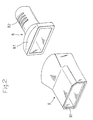
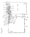
- a plug-type multipolar electrical connector has a first shield cover 1, a second shield cover 2, a body 3, locking members 4, sliders 5 and the like.
- the first shield cover 1 is formed by bending a metallic plate into a rectangular case.
- the first shield cover 1 is provided at the front end portion thereof with a pair of lateral plates 11, a bottom plate 12, a top plate 13, and inclined plates 14 between the top plate 13 and the lateral plates 11.
- the top plate 13 has an engagement pawl 15 opened in the forward direction A and engagement pawls 16 opened in the rearward direction B, these engagement pawls 15, 16 being formed as cut and inwardly turned.
- the bottom plate 12 also has an engagement pawl opened in the forward direction A and engagement pawls opened in the rearward direction B, these engagement pawls being formed as cut and inwardly turned.
- the shape in front elevation of the first shield cover 1 at the front end portion thereof is the same as that of the body 3 shown in Figs. 1 and 4.
- the body 3 is fitted into the front end portion of the first shield cover 1.
- the body 3 is provided at the top side and the underside thereof with stepped engagement portions 31, 32.
- stepped engagement portions 31, 32 By engaging these stepped engagement portions 31, 32 with the corresponding engagement pawls 15, 16, the body 3 is connected to the first shield cover 1 as shown in Fig. 3. It is noted that Fig. 1 does not show the stepped engagement portions formed in the underside of the body 3.
- the lateral plates 11 are provided at the rear end portions thereof with engagement pawls 17 (See Figs. 1 and 5) which are formed as cut and outwardly turned and which are opened in the rearward direction.
- the top plate 13 and the bottom plate 12 are provided at the rear end portions thereof with engagement holes 18, 19 (See Figs. 1 and 5).
- the second shield cover 2 is formed by drawing a metallic plate.
- the second shield cover 2 has, in a unitary structure, an attaching neck portion 21 and a fitting case portion 22 extending therefrom.
- the fitting case portion 22 has the same shape as that of the rear end portion of the first shield cover 1 and has sizes such that the rear end portion of the first shield cover 1 can be fitted into the fitting case portion 22.
- the second shield cover 2 has engagement pawls 23, 24 which are formed as cut and inwardly turned and which are opened in the rearward direction.
- first shield cover 1 When the rear end portion of the first shield cover 1 is fitted into the fitting case portion 22 of the second shield cover 2, these engagement pawls 23, 24 are respectively engaged with the corresponding engagement holes 18, 19 in the first shield cover 1, and the engagement pawls 17 of the first shield cover 1 are engaged with the front end edges of the fitting case portion 22 as shown in Fig. 5.
- the first shield cover 1 is connected to the second shield cover 2.
- the fitted portions (i. e., the overlapping portions) of the first shield cover 1 and the second shield cover 2 may be soldered to each other to improve the shielding performance.
- a composite cable 100 is of the same type as that discussed in connection with Fig. 14, and comprises thin conductors 130 and thick conductors 140 incorporated in a braided shell shield 110.
- the composite cable 100 is provided in the vicinity of the tip thereof with a ring body 6 put thereon.
- a portion of the braided shell shield 110 is folded back on the outer surface of the ring body 6.
- the attaching neck portion 21 of the second shield cover 2 is put on the ring body 6, and the braided shell shield 110 is held by and between the ring body 6 and the attaching neck portion 21. Accordingly, the second shield cover 2 is securely electrically contacted with the braided shell shield 110. This improves the connector in shielding operation in an area including the first shield cover 1.
- the attaching neck portion 21 is calked or the overlapping portions of the ring body 6 and the braided shell shield 110 are soldered to each other, the shielding operation is further improved.
- the body 3 is molded from an insulating resin.
- a number of horizontal terminal pin attaching holes are formed as arranged in a grid manner in both transverse and longitudinal directions. As shown in Fig. 4, out of these terminal pin attaching holes, a first attaching hole group 33 formed at the center of the body 3 has first attaching holes 33a in which the horizontal pitch P1 between each adjacent holes is fine.
- a second attaching hole group 34 at one side of the first attaching hole group 33 has second attaching holes 34a in which the horizontal pitch P2 between each adjacent holes is coarse.
- a third attaching hole group 35 at the other side of the first attaching hole group 33 has third attaching holes 35a in which the horizontal pitch P3 between each adjacent holes is fine.
- P1 is equal to P3 which is smaller than P2.
- terminal pins 37a, 38a are inserted into the first attaching holes 33a, the second attaching holes 34a and the third attaching holes 35a such that the terminal pins 37a, 38a project in the forward direction A.
- the terminal pins 37a inserted into the first attaching hole group 33 and into the third attaching hole group 35 are used for thin conductors, and the terminal pins 38a inserted into the second attaching hole group 34 are used for thick conductors.
- the terminal pins 37a for thin conductors form a thin conductor terminal pin group at each of the center and the other side of the body 3, and the terminal pins 38a for thick conductors form a thick conductor terminal pin group at one side of the body 3.
- the thin conductors 130 exposed at the tip of the composite cable 100 are gathered to the center and the other side of the body 3 and respectively connected to the corresponding thin conductor terminal pins 37a, and the thick conductors 140 are gathered to one side of the body 3 and respectively connected to the corresponding thick conductor terminal pins 38a.
- the thin conductors 130 and the thick conductors 140 are not mixingly present, and a space necessary for handling the thin conductors 130 can be reduced. This restrains the body 3 and consequently the plug-type multipolar electrical connector from being increased in size. Thus, the plug-type multipolar electrical connector satisfies the demand for miniaturization and higher density.
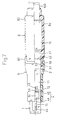
- the first shield cover 1 is provided in each of the lateral plates 11 with an opening 7 which extends in the longitudinal direction A-B.
- Each opening 7 has a forward narrow-width part 71 and a rearward wide-width part 72.
- Each locking member 4 has, in a unitary structure, a resilient movable piece 41 and a holding frame 42 integrally formed at the base end of the movable piece 41.
- a projection 44 is formed by bending the tip of each movable piece 41.
- a space for housing a spring member 53 is formed between a pair of upper and lower flat plates 42a, and flange portions 42b are formed by bending the flat plates 42a.
- a tongue-like spring receiving portion 43 is formed at the rear end of each holding frame 42.
- a slide piece 52 projects from the lateral side of a base portion 51.
- the locking members 4 are fitted into the openings 7 of the first shield cover 1.
- the movable pieces 41 of the locking members 4 are housed in the narrow-width parts 71
- the projections 44 project from the lateral plates 11 of the first shield cover 1
- the holding frames 42 are fitted into the wide-width parts 72 in the openings 7.
- the flange portions 42b are opposite to and come in contact with the outer surfaces of the lateral plates 11, engagement pawls (not shown) formed at the flat plates 42a are engaged with the inner surfaces of the lateral plates 11, so that the holding frames 42 are secured to the lateral plates 11.
- the slide pieces 52 of the sliders 5 are disposed in an overlapping manner throughout the back sides of the movable pieces 41 of the locking members 4 attached to the first shield cover 1, and the base portions 51 of the sliders 5 are longitudinally movably fitted to the holding frames 42 of the locking members 4.
- the spring members 53 comprising coil springs are interposed as compressed between the base portions 51 of the sliders 5 and the spring receiving portions 43 formed in the holding frames 42 of the locking members 4. The spring members 53 normally bias the sliders 5 in the forward direction A.
- Fig. 2 shows a strain relief 8 and a sleeve 9.
- the strain relief 8 has a cover portion 81 and a case portion 82. As shown in Figs. 6 and 7, the cover portion 81 is put on the second shield cover 2, and the case portion 82 covers the composite cable 100 in such a manner as to envelop a ferrite core 10 put on the composite cable 100.
- a molded article may be used as mounted on the second shield cover 2 and the composite cable 100 as above-mentioned, or the strain relief 8 may be formed by injection molding.
- the sleeve 9 is made in the form of a case of which shape is similar to the shape in front elevation of the first shield cover 1.
- the sleeve 9 is longitudinally slidably put on the first shield cover 1.
- the rear end portion of the sleeve 9 is slidably put on the cover portion 81 of the strain relief 8.
- the sleeve 9 is provided at the inner periphery of the front end thereof with an inwardly projecting engagement portion 91.
- the engagement portion 91 is disposed rearward with respect to the projections 44 such that the engagement portion 91 is engageable, only from the front side thereof, with the front ends of the base portions 51 of the sliders 5.
- Fig. 6 the engagement portion 91 is disposed rearward with respect to the projections 44 such that the engagement portion 91 is engageable, only from the front side thereof, with the front ends of the base portions 51 of the sliders 5.
- the sleeve 9 is provided at the rear end thereof with an engagement pawl 92.
- This engagement pawl 92 is opposite to a stepped engagement portion 83 of the cover portion 81 of the strain relief 8, thus preventing the sleeve 9 from coming off.
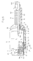
- a socket-type multipolar electrical connector which is a counter electrical connector of the plug-type multipolar electrical connector.
- a socket-type multipolar electrical connector comprises a shield cover 201 and a body 200 fitted therein.
- the shield cover 201 is formed by bending a metallic plate.
- the shield cover 201 has a rectangular case portion 202 having a pair of lateral plates 203, each of which is provided with an engagement hole 204 and an expanded guide 206.
- the body 200 is provided on the lateral sides thereof with projecting portions 205. Predetermined gaps are formed between the projecting portions 205 and the lateral plates 203 of the shield cover 201. It is a matter of course that the body 200 has terminal pin groups (not shown) corresponding to the terminal pin groups of the body 3 of the plug-type multipolar electrical connector above-mentioned.
- the first shield cover 1 of the plug-type multipolar electrical connector is inserted into the shield cover 201 of the socket-type multipolar electrical connector in a direction shown by an arrow X.
- the projections 44 of the locking members 4 are guided by the guides 206 of the shield cover 201, so that the movable pieces 41 are inwardly displaced with the slide pieces 52 of the sliders 5 bent.
- the tips of the slide pieces 52 come in contact with the projecting portions 205 of the body 200 of the socket-type multipolar electrical connector, as shown in Fig. 10.
- the sliders 5 are pushed out by the spring loads of the spring members 53, so that the slide pieces 52 are fitted into the gaps as shown in Fig. 12. Accordingly, the slide pieces 52 are backed up from the back sides thereof by the projecting portions 205 to prevent the movable pieces 41 from being inwardly displaced. Accordingly, even though the composite cable 100 or the strain relief 8 is pulled, there is no possibility of the projections 44 coming out from the engagement holes 204. Thus, the plug-type multipolar electrical connector is prevented from unexpectedly coming out from the socket-type multipolar electrical connector.
- the inserting operation above-mentioned may be carried out with the sleeve 9 or the strain relief 8 of the plug-type multipolar electrical connector held with the hand.
- the plug-type multipolar electrical connector For pulling out the plug-type multipolar electrical connector as connected to the socket-type multipolar electrical connector as shown in Fig. 12, from the socket-type multipolar electrical connector, the plug-type multipolar electrical connector can be pulled out in a direction shown by an arrow Y in Fig. 13 with the sleeve 9 held with the hand.
- the engagement portion 91 of the sleeve 9 engaged with the front ends of the base portions 51 of the sliders 5 pushes the base portions 51 in the rearward direction B (See Fig. 1), so that the sliders 5 are retreated against the spring loads of the spring members 53.
- Fig. 1 See FIG. 1
- the slide pieces 52 come out from between the projecting portions 205 and the movable pieces 41 to form gaps between the movable pieces 41 and the projecting portions 205.
- the plug-type multipolar electrical connector of the present invention is of the so-called one-touch full locking type that each of the inserting and pulling operations can be carried out by pushing or pulling the sleeve 9 as held with the hand. Accordingly, the plug-type multipolar electrical connector is convenient to use. Further, the projections 44 are engaged with the engagement holes 204 at the left- and right-hands of the both electrical connectors, enabling the inserting and pulling operations to be carried out in a well balanced manner. Further, the locking members 4 are separated from the first shield cover 1, and the spring members 53 are housed in the holding frames 42 of the locking members 4.
- the first shield cover 1 has only the openings 7 into which the locking members 4 are fitted, and it is not required to form openings through which the spring members 53 are disposed. This minimizes a decrease in shielding performance due to the formation of such openings.
Landscapes
- Details Of Connecting Devices For Male And Female Coupling (AREA)
Claims (6)
- Connecteur électrique multipolaire mâle possédant un corps (3) en matériau isolant, dans lequel une pluralité de broches (37a, 38a) sont assemblées de manière à faire saillie vers l'avant, connecteur qui comprend :un premier recouvrement de blindage qui est disposé de manière à entourer le corps (3) et les broches (37a, 38a) ;une bague (6) enfilée de façon ajustée sur un câble composite (100) etun second recouvrement de blindage à mettre par-dessus la bague (6), caractérisé en ceque le premier recouvrement de blindage (1) est réalisé d'une feuille métallique,que le second recouvrement de blindage (2) comporte, dans une structure d'un seul tenant, un col de fixation (21) enfilé avec ajustement par-dessus la bague (6) attachée au câble composite (100),qu'une partie de boîtier (22) d'assemblage adaptée s'étend à partir du col (21) et est fixée audit premier recouvrement de blindage (1) ;que la partie extrême arrière du premier recouvrement de blindage (1) est fixée à la partie de boîtier d'assemblage (22) du second recouvrement de blindage (2),que ledit second recouvrement de blindage (2) porte des cliquets d'assemblage (23, 24) constitués par des languettes découpées, incurvées vers l'intérieur et dirigées vers l'arrière, cliquets qui sont engagés dans des trous d'assemblage (18) correspondants formés dans ledit premier recouvrement de blindage (1) etque ledit premier recouvrement de blindage (1) porte des cliquets d'assemblage (17) dirigés vers l'arrière et venant s'appliquer contre le bord avant de la partie de boîtier d'assemblage (22),de telle sorte que le premier recouvrement de blindage (1) est relié au second recouvrement de blindage (2).
- Connecteur multipolaire mâle selon la revendication 1, comprenant :un premier recouvrement de blindage (1) comportant deux parois latérales (11) ;des ouvertures (7) ménagées dans les parois latérales (11) et orientées dans la direction longitudinale de ces parois ;des pièces de verrouillage (4) possédant, d'un seul tenant, des lames élastiquement flexibles (41) pourvues de saillies ou renflements (44) à leurs extrémités avant, et à leurs extrémités de base, de supports creux (42) présentant des logements pour des ressorts (53) ;des pièces coulissantes ou coulisses (5) possédant, d'un seul tenant, des parties de base (51) montées sur les supports (42) des pièces de verrouillage (4) pour pouvoir coulisser longitudinalement sur eux, ainsi que des cales (52) s'étendant à partir des parties de base le long des côtés arrière des lames flexibles (41), de manière à les recouvrir ;des ressorts (53) placés dans lesdits logements des supports (42), entre les parties de base (51) des coulisses (5) et des appuis de ressort formés sur ces supports, les ressorts (53) ayant normalement tendance à pousser les coulisses (5) vers l'avant ; etun manchon (9) disposé et monté longitudinalement coulissant sur le premier recouvrement de blindage (1), manchon qui possède une partie formant butée (91) qui est applicable, uniquement à partir du côté avant des coulisses, contre les extrémités frontales des parties de base (51) des coulisses (5),les pièces de verrouillage (4) étant montées dans les ouvertures (7) de manière que les renflements (44) des lames flexibles (41) dépassent des parois latérales (11) du premier recouvrement de blindage (1),les supports (42) des pièces de verrouillage (4) étant appliqués contre les bords arrière des ouvertures (7),etles portions des extrémités frontales des parties de base (51) des coulisses (5) contre lesquelles s'applique la partie formant butée (91) du manchon (9), étant situées à l'arrière par rapport aux renflements des lames flexibles.
- Connecteur multipolaire mâle selon la revendication 2, dans lequel les ouvertures (7) comportent des parties avant (71) relativement étroites et des parties arrière (72) plus larges, les lames flexibles (41) des pièces de verrouillage (4) étant situées dans les parties étroites (71) et les supports (42) des pièces de verrouillage (4) étant situées dans les parties larges (72).
- Connecteur multipolaire mâle selon la revendication 2, dans lequel les supports (42) des pièces de verrouillage (4) comportent des paires de parois planes (42a), respectivement supérieures et inférieures, qui délimitent les logements pour les ressorts (53), et des rebords (42b) formés par pliage des parois (42a), les rebords (42b) étant opposés aux surfaces extérieures autour des ouvertures (7) des parois latérales (11) du premier recouvrement de blindage (1) et en contact avec elles.
- Connecteur multipolaire mâle selon la revendication 3, dans lequel les supports (42) des pièces de verrouillage (4) comportent des paires de parois planes (42a), respectivement supérieures et inférieures, qui délimitent les logements pour les ressorts (53), ainsi que des rebords (42b) formés par pliage des parois (42a), les rebords (42b) étant opposés aux surfaces extérieures autour des ouvertures (7) des parois latérales (11) du premier recouvrement de blindage (1) et en contact avec elles.
- Connecteur multipolaire mâle selon la revendication 2, comprenant en outre une pièce de décharge de traction (8) avec une partie de couverture (81) et une partie de boîtier (82), la partie (81) étant mise en place sur le second recouvrement de blindage (2) et la partie (82) recouvrant l'extrémité du câble composite (100) et un noyau de ferrite (10) disposé sur ce câble, la partie extrême arrière du manchon (9) étant glissée par-dessus la partie (81) de la pièce de décharge de traction (8).
Applications Claiming Priority (2)
| Application Number | Priority Date | Filing Date | Title |
|---|---|---|---|
| JP1992015664U JP2595406Y2 (ja) | 1992-03-25 | 1992-03-25 | プラグ型多極コネクタ |
| JP15664/92 | 1992-03-25 |
Publications (3)
| Publication Number | Publication Date |
|---|---|
| EP0562311A2 EP0562311A2 (fr) | 1993-09-29 |
| EP0562311A3 EP0562311A3 (en) | 1994-11-23 |
| EP0562311B1 true EP0562311B1 (fr) | 1997-06-04 |
Family
ID=11895012
Family Applications (1)
| Application Number | Title | Priority Date | Filing Date |
|---|---|---|---|
| EP93103335A Expired - Lifetime EP0562311B1 (fr) | 1992-03-25 | 1993-03-02 | Connecteur électrique multipolaire à fiches |
Country Status (5)
| Country | Link |
|---|---|
| US (1) | US5338227A (fr) |
| EP (1) | EP0562311B1 (fr) |
| JP (1) | JP2595406Y2 (fr) |
| DE (1) | DE69311177T2 (fr) |
| SG (1) | SG40036A1 (fr) |
Cited By (2)
| Publication number | Priority date | Publication date | Assignee | Title |
|---|---|---|---|---|
| DE102004046259B3 (de) * | 2004-09-23 | 2006-03-09 | Harting Electronics Gmbh & Co. Kg | Verriegelung für eine Steckverbindung |
| US7077703B2 (en) | 2003-06-03 | 2006-07-18 | Delphi Technologies, Inc | Plug connector |
Families Citing this family (59)
| Publication number | Priority date | Publication date | Assignee | Title |
|---|---|---|---|---|
| JPH06208866A (ja) * | 1992-12-07 | 1994-07-26 | Fujitsu Ltd | コネクタ |
| NL9202302A (nl) * | 1992-12-31 | 1994-07-18 | Du Pont Nederland | Koaxiaal interkonnektiesysteem. |
| US5518421A (en) * | 1993-01-26 | 1996-05-21 | The Whitaker Corporation | Two piece shell for a connector |
| SE501020C2 (sv) * | 1993-05-19 | 1994-10-24 | Ericsson Telefon Ab L M | Jordningsanordning för ett knippe skärmade kablar |
| JP2982100B2 (ja) * | 1994-02-03 | 1999-11-22 | 矢崎総業株式会社 | シールドコネクタ |
| JP2978950B2 (ja) * | 1994-05-25 | 1999-11-15 | モレックス インコーポレーテッド | シールドコネクタ |
| SE506097C2 (sv) * | 1994-11-22 | 1997-11-10 | Celsiustech Electronics Ab | Anslutningsdon |
| US5529512A (en) * | 1994-12-30 | 1996-06-25 | Methode Electronics, Inc. | Connector with low insertion force |
| JP3097816B2 (ja) * | 1995-03-10 | 2000-10-10 | 矢崎総業株式会社 | シールド線のシースずれ防止構造 |
| JPH11502971A (ja) * | 1995-03-27 | 1999-03-09 | ザ ウィタカー コーポレーション | 電気コネクタのためのシールド組立体 |
| US5788537A (en) * | 1995-03-27 | 1998-08-04 | The Whiteker Corporation | Shield assembly for an electrical connector |
| US5683269A (en) * | 1995-03-27 | 1997-11-04 | The Whitaker Corporation | Shielded electrical connector with cable strain relief |
| JP3064874B2 (ja) * | 1995-06-12 | 2000-07-12 | ソニー株式会社 | コネクタプラグ |
| US5554045A (en) * | 1995-06-19 | 1996-09-10 | Itt Cannon, Inc. | Latch for IC card connector |
| US5586893A (en) * | 1995-07-17 | 1996-12-24 | Itt Corporation | IC card connector shield grounding |
| JPH0935816A (ja) * | 1995-07-19 | 1997-02-07 | Whitaker Corp:The | ラッチ付電気コネクタ |
| GB2303974B (en) * | 1995-07-28 | 1999-06-16 | Cinch Connectors Ltd | Electrical connector |
| US5618196A (en) * | 1995-08-18 | 1997-04-08 | Lucent Technologies, Inc. | Socket connector having improved protection against electrostatic discharges |
| JP2978953B2 (ja) * | 1995-12-29 | 1999-11-15 | モレックス インコーポレーテッド | プラグ型電気コネクタとその製造方法 |
| JP3180016B2 (ja) * | 1996-02-08 | 2001-06-25 | 矢崎総業株式会社 | 半嵌合防止コネクタ |
| JP3285307B2 (ja) * | 1996-03-07 | 2002-05-27 | 矢崎総業株式会社 | 半嵌合防止コネクタ |
| US6007379A (en) * | 1997-02-10 | 1999-12-28 | Thomas & Betts International, Inc. | Electrical connector assembly |
| TW335229U (en) * | 1997-03-21 | 1998-06-21 | Hon Hai Prec Ind Co Ltd | Plug connector |
| US5913698A (en) * | 1997-05-01 | 1999-06-22 | Hon Hai Precision Ind. Co., Ltd. | Shielded connector |
| USD414743S (en) | 1998-03-31 | 1999-10-05 | Honda Tsushin Kogyo Co., Ltd. | Female connector |
| TW464109U (en) * | 1998-12-11 | 2001-11-11 | Hon Hai Prec Ind Co Ltd | Cable connector device |
| SG109416A1 (en) * | 1999-01-26 | 2005-03-30 | Molex Inc | Electrical connector with locking mechanism and metal spring |
| US6506077B2 (en) | 2000-07-21 | 2003-01-14 | The Siemon Company | Shielded telecommunications connector |
| JP2002110295A (ja) * | 2000-10-02 | 2002-04-12 | Tyco Electronics Amp Kk | 電気コネクタ組立体およびこれに用いられる雄コネクタ |
| JP3777980B2 (ja) * | 2000-12-25 | 2006-05-24 | 住友電装株式会社 | 分割コネクタ |
| US6358082B1 (en) * | 2001-02-12 | 2002-03-19 | Berg Technology, Inc. | Latch and release mechanism for an electrical connector |
| USD481681S1 (en) | 2002-01-21 | 2003-11-04 | Molex Incorporated | Electrical connector |
| TW525853U (en) * | 2002-03-21 | 2003-03-21 | Je-Jia Jang | Electrical connector |
| USD478050S1 (en) | 2002-05-29 | 2003-08-05 | Mitsumi Electric Co., Ltd. | Electrical connector |
| TW570388U (en) * | 2003-01-29 | 2004-01-01 | Hon Hai Prec Ind Co Ltd | Cable connector assembly |
| JP4234492B2 (ja) * | 2003-02-10 | 2009-03-04 | 古河電気工業株式会社 | シールドコネクタ |
| TW573839U (en) * | 2003-06-27 | 2004-01-21 | Hon Hai Prec Ind Co Ltd | Cable connector assembly |
| US6966797B2 (en) * | 2003-12-15 | 2005-11-22 | Hon Hai Precision Ind. Co., Ltd. | High-speed cable assembly |
| US6887091B1 (en) * | 2003-12-24 | 2005-05-03 | Hon Hai Precision Ind. Co., Ltd. | Cable connector assembly having additional pull tab |
| JP4377727B2 (ja) * | 2004-03-25 | 2009-12-02 | 株式会社オートネットワーク技術研究所 | シールドコネクタ |
| USD523813S1 (en) * | 2004-06-01 | 2006-06-27 | Hon Hai Precision Ind. Co., Ltd. | Electrical connector |
| JP2006107992A (ja) * | 2004-10-07 | 2006-04-20 | Honda Tsushin Kogyo Co Ltd | ケーブルコネクタ |
| TWD112249S1 (zh) * | 2004-11-15 | 2006-08-01 | 三美電機股份有限公司 | 連接器(六) |
| TWD117740S1 (zh) * | 2004-11-15 | 2007-06-21 | 三美電機股份有限公司 | 連接器(七) |
| US20060200169A1 (en) * | 2005-03-07 | 2006-09-07 | Kevin Sniffin | Specimen retrieval apparatus and method of use |
| TWI276857B (en) * | 2005-06-10 | 2007-03-21 | Delta Electronics Inc | A connecting module for communication |
| USD523400S1 (en) * | 2005-07-13 | 2006-06-20 | Advanced Connectek, Inc. | Electrical connector |
| US7165996B1 (en) * | 2005-08-04 | 2007-01-23 | T-Conn Precision Corp. | Cable connector with anti-electromagnetic interference capability |
| TWM295417U (en) * | 2005-12-01 | 2006-08-01 | Wistron Corp | Interface card with a mechanism for covering a golden finger thereof |
| FR2934422B1 (fr) * | 2008-07-28 | 2015-10-02 | Nicomatic Sa | Connecteur blinde |
| US8323043B2 (en) | 2008-08-29 | 2012-12-04 | Adc Gmbh | Electrical connector having movable shield to protect electrical contacts |
| EP2556565B1 (fr) * | 2010-04-09 | 2018-10-03 | Delphi International Operations Luxembourg S.à r.l. | Dispositif de blindage électromagnétique |
| US20130296729A1 (en) | 2012-05-04 | 2013-11-07 | Biosense Webster (Israel), Ltd. | Catheter having two-piece connector for a split handle assembly |
| JP6114675B2 (ja) * | 2013-10-24 | 2017-04-12 | 日本航空電子工業株式会社 | レセプタクルコネクタ |
| DE102014103834B4 (de) * | 2014-03-20 | 2018-07-05 | Phoenix Contact Gmbh & Co. Kg | Störfester Steckverbinder |
| CN106415944A (zh) | 2014-04-23 | 2017-02-15 | 泰科电子公司 | 具有屏蔽帽和屏蔽端子的电连接器 |
| JP6717168B2 (ja) | 2016-11-11 | 2020-07-01 | 住友電装株式会社 | シールドシェルおよびシールドコネクタ |
| US10177467B1 (en) * | 2017-09-21 | 2019-01-08 | Te Connectivity Corporation | Cable connector assembly with backshell |
| US10790619B2 (en) | 2018-07-12 | 2020-09-29 | Cinch Connectors, Inc. | Shielded cable system for the shielding and protection against emi-leakage and impedance control |
Family Cites Families (15)
| Publication number | Priority date | Publication date | Assignee | Title |
|---|---|---|---|---|
| DE2259231A1 (de) * | 1972-12-04 | 1974-06-06 | Bosch Gmbh Robert | Mehrpoliger anschlussockel fuer elektrische geraete mit steckanschluessen |
| JPS57199977U (fr) * | 1981-06-17 | 1982-12-18 | ||
| FR2544558B1 (fr) * | 1983-04-15 | 1986-06-27 | Deutsch Co | Connecteur perfectionne |
| ATE39596T1 (de) * | 1985-01-18 | 1989-01-15 | Hosiden Electronics Co | Steckverbinder mit verriegelungsmechanismus. |
| JPS62188186A (ja) * | 1986-02-14 | 1987-08-17 | 日産自動車株式会社 | 複合コネクタの端子の二重係止機構 |
| JPH0231737Y2 (fr) * | 1986-06-11 | 1990-08-28 | ||
| DE8630023U1 (de) * | 1986-11-10 | 1987-08-20 | Guglhör, Magdalena, 8959 Buching | Mischpolleiste für elektronische Bauteile |
| JPH0530307Y2 (fr) * | 1987-02-12 | 1993-08-03 | ||
| JPH0441582Y2 (fr) * | 1987-09-24 | 1992-09-30 | ||
| US4929189A (en) * | 1988-04-13 | 1990-05-29 | Hosiden Electronics Co., Ltd. | Connector with locking mechanism |
| DE3873749T2 (de) * | 1988-05-05 | 1993-02-04 | Hosiden Corp | Vielpoliger steckbverbinder. |
| JPH0718128Y2 (ja) * | 1989-04-17 | 1995-04-26 | ホシデン株式会社 | 多極コネクタ |
| JPH0733403Y2 (ja) * | 1989-12-04 | 1995-07-31 | ホシデン株式会社 | コネクタ |
| JPH0810933Y2 (ja) * | 1990-01-16 | 1996-03-29 | 日本電気株式会社 | 同軸型コネクタ |
| US5109452A (en) * | 1990-07-16 | 1992-04-28 | Puritan-Bennett Corporation | Electrical-optical hybrid connector |
-
1992
- 1992-03-25 JP JP1992015664U patent/JP2595406Y2/ja not_active Expired - Fee Related
-
1993
- 1993-02-25 US US08/022,318 patent/US5338227A/en not_active Expired - Lifetime
- 1993-03-02 DE DE69311177T patent/DE69311177T2/de not_active Expired - Fee Related
- 1993-03-02 EP EP93103335A patent/EP0562311B1/fr not_active Expired - Lifetime
- 1993-03-02 SG SG1995001543A patent/SG40036A1/en unknown
Cited By (3)
| Publication number | Priority date | Publication date | Assignee | Title |
|---|---|---|---|---|
| US7077703B2 (en) | 2003-06-03 | 2006-07-18 | Delphi Technologies, Inc | Plug connector |
| DE102004046259B3 (de) * | 2004-09-23 | 2006-03-09 | Harting Electronics Gmbh & Co. Kg | Verriegelung für eine Steckverbindung |
| CN100486050C (zh) * | 2004-09-23 | 2009-05-06 | 哈廷电子有限公司及两合公司 | 用于插塞连接的锁紧装置 |
Also Published As
| Publication number | Publication date |
|---|---|
| JP2595406Y2 (ja) | 1999-05-31 |
| SG40036A1 (en) | 1997-06-14 |
| EP0562311A2 (fr) | 1993-09-29 |
| US5338227A (en) | 1994-08-16 |
| JPH0577878U (ja) | 1993-10-22 |
| DE69311177T2 (de) | 1997-09-18 |
| DE69311177D1 (de) | 1997-07-10 |
| EP0562311A3 (en) | 1994-11-23 |
Similar Documents
| Publication | Publication Date | Title |
|---|---|---|
| EP0562311B1 (fr) | Connecteur électrique multipolaire à fiches | |
| EP0981180B1 (fr) | Connecteur blindé | |
| US5941733A (en) | Universal serial bus plug connector | |
| US6200162B1 (en) | Shielding terminal | |
| KR970004148B1 (ko) | 암수형 이중 잠금 커넥터 | |
| US6866535B2 (en) | Plug and receptacle | |
| EP0263654B1 (fr) | Fiche électrique et assemblage d'un réceptacle de connecteur | |
| EP0907221A2 (fr) | Connecteur pour câbles électriques | |
| EP1174949B1 (fr) | Borne blindée et procédé de montage | |
| US20050136738A1 (en) | Shielded Connector | |
| US6129594A (en) | Electrical connector | |
| EP0653815B1 (fr) | Connecteur électrique avec borne de terre pour écran de câble | |
| JPH0227674A (ja) | 電気コネクタ | |
| US6929512B2 (en) | Cable end connector assembly with a shield device | |
| US5401177A (en) | Mass termination connector backshell | |
| JPH04109573A (ja) | 電気コネクタ及びその製造方法 | |
| KR20030044875A (ko) | 결속 부분을 구비한 차폐 외피를 가지는 커넥터 | |
| US5584718A (en) | Branch-connection connector | |
| US20090047825A1 (en) | Cable connector assembly with protective stiffener | |
| US6984151B2 (en) | Electrical connector with non-conductive cover | |
| KR960002139B1 (ko) | 전기 커넥터 조립체 | |
| EP1548894B1 (fr) | Connecteur | |
| US5230636A (en) | Terminal protection type connector | |
| JP3423786B2 (ja) | 2重シールドコネクタ | |
| EP0601265B1 (fr) | Connecteur électrique multipolaire à douille |
Legal Events
| Date | Code | Title | Description |
|---|---|---|---|
| PUAI | Public reference made under article 153(3) epc to a published international application that has entered the european phase |
Free format text: ORIGINAL CODE: 0009012 |
|
| AK | Designated contracting states |
Kind code of ref document: A2 Designated state(s): DE FR GB IE |
|
| PUAL | Search report despatched |
Free format text: ORIGINAL CODE: 0009013 |
|
| AK | Designated contracting states |
Kind code of ref document: A3 Designated state(s): DE FR GB IE |
|
| 17P | Request for examination filed |
Effective date: 19950510 |
|
| 17Q | First examination report despatched |
Effective date: 19950825 |
|
| GRAG | Despatch of communication of intention to grant |
Free format text: ORIGINAL CODE: EPIDOS AGRA |
|
| GRAH | Despatch of communication of intention to grant a patent |
Free format text: ORIGINAL CODE: EPIDOS IGRA |
|
| GRAH | Despatch of communication of intention to grant a patent |
Free format text: ORIGINAL CODE: EPIDOS IGRA |
|
| GRAA | (expected) grant |
Free format text: ORIGINAL CODE: 0009210 |
|
| AK | Designated contracting states |
Kind code of ref document: B1 Designated state(s): DE FR GB IE |
|
| ET | Fr: translation filed | ||
| REF | Corresponds to: |
Ref document number: 69311177 Country of ref document: DE Date of ref document: 19970710 |
|
| PLBE | No opposition filed within time limit |
Free format text: ORIGINAL CODE: 0009261 |
|
| STAA | Information on the status of an ep patent application or granted ep patent |
Free format text: STATUS: NO OPPOSITION FILED WITHIN TIME LIMIT |
|
| 26N | No opposition filed | ||
| REG | Reference to a national code |
Ref country code: GB Ref legal event code: IF02 |
|
| PGFP | Annual fee paid to national office [announced via postgrant information from national office to epo] |
Ref country code: FR Payment date: 20060313 Year of fee payment: 14 |
|
| PGFP | Annual fee paid to national office [announced via postgrant information from national office to epo] |
Ref country code: DE Payment date: 20060314 Year of fee payment: 14 |
|
| PGFP | Annual fee paid to national office [announced via postgrant information from national office to epo] |
Ref country code: GB Payment date: 20060322 Year of fee payment: 14 |
|
| PGFP | Annual fee paid to national office [announced via postgrant information from national office to epo] |
Ref country code: IE Payment date: 20060330 Year of fee payment: 14 |
|
| GBPC | Gb: european patent ceased through non-payment of renewal fee |
Effective date: 20070302 |
|
| REG | Reference to a national code |
Ref country code: IE Ref legal event code: MM4A |
|
| REG | Reference to a national code |
Ref country code: FR Ref legal event code: ST Effective date: 20071130 |
|
| PG25 | Lapsed in a contracting state [announced via postgrant information from national office to epo] |
Ref country code: IE Free format text: LAPSE BECAUSE OF NON-PAYMENT OF DUE FEES Effective date: 20070302 Ref country code: DE Free format text: LAPSE BECAUSE OF NON-PAYMENT OF DUE FEES Effective date: 20071002 |
|
| PG25 | Lapsed in a contracting state [announced via postgrant information from national office to epo] |
Ref country code: GB Free format text: LAPSE BECAUSE OF NON-PAYMENT OF DUE FEES Effective date: 20070302 |
|
| PG25 | Lapsed in a contracting state [announced via postgrant information from national office to epo] |
Ref country code: FR Free format text: LAPSE BECAUSE OF NON-PAYMENT OF DUE FEES Effective date: 20070402 |