EP0562326A1 - Transducteur ultrasonore atmosphérique - Google Patents
Transducteur ultrasonore atmosphérique Download PDFInfo
- Publication number
- EP0562326A1 EP0562326A1 EP93103482A EP93103482A EP0562326A1 EP 0562326 A1 EP0562326 A1 EP 0562326A1 EP 93103482 A EP93103482 A EP 93103482A EP 93103482 A EP93103482 A EP 93103482A EP 0562326 A1 EP0562326 A1 EP 0562326A1
- Authority
- EP
- European Patent Office
- Prior art keywords
- curvatures
- air
- curvature
- ultrasonic transducer
- foils
- Prior art date
- Legal status (The legal status is an assumption and is not a legal conclusion. Google has not performed a legal analysis and makes no representation as to the accuracy of the status listed.)
- Withdrawn
Links
Images

Classifications
-
- B—PERFORMING OPERATIONS; TRANSPORTING
- B06—GENERATING OR TRANSMITTING MECHANICAL VIBRATIONS IN GENERAL
- B06B—METHODS OR APPARATUS FOR GENERATING OR TRANSMITTING MECHANICAL VIBRATIONS OF INFRASONIC, SONIC, OR ULTRASONIC FREQUENCY, e.g. FOR PERFORMING MECHANICAL WORK IN GENERAL
- B06B1/00—Methods or apparatus for generating mechanical vibrations of infrasonic, sonic, or ultrasonic frequency
- B06B1/02—Methods or apparatus for generating mechanical vibrations of infrasonic, sonic, or ultrasonic frequency making use of electrical energy
- B06B1/06—Methods or apparatus for generating mechanical vibrations of infrasonic, sonic, or ultrasonic frequency making use of electrical energy operating with piezoelectric effect or with electrostriction
- B06B1/0688—Methods or apparatus for generating mechanical vibrations of infrasonic, sonic, or ultrasonic frequency making use of electrical energy operating with piezoelectric effect or with electrostriction with foil-type piezoelectric elements, e.g. PVDF
Definitions
- the present invention relates to an air ultrasound transducer, formed from one or more self-supporting foils made of piezoelectric material, in particular polymer material and electrodes for applying an electrical excitation signal, the foil or foils having curvatures.
- Air-ultrasonic transducers of the type mentioned at the outset are already known from US Pat. Nos. 3,852,580 and 4,088,915 and DD Patent 224,503. Frequently, the transducers are mechanically supported and damped at the same time by a rear foam body (see US Pat. No. 3,852,580, FIGS. 21, 22, 24; DD PS 224 503).
- the damping which results from the mechanical losses in the polymer material and the rear damping with foam-supported foils, leads to a significantly wider range than is usual with piezoceramic transducers. With the increased damping, however, the formwork performance decreases at the same time. From US Pat. No.
- 3,852,580 it is also known to construct a sound transducer from a plurality of similar individual elements arranged next to one another in one plane.
- sound transducers are known in which a multi-curved surface is realized by the corresponding shaping of a single coherent piezopolymer film.
- the bulges can be arranged in parallel or in the form of concentric rings.
- the apexes of the curvature lie in one plane in order to achieve a conspicuous sound radiation in the direction of the acoustic transducer axis.
- Multi-element sound transducers are also known from US Pat. Nos. 4,460,841 and 4,395,652, in which the directional characteristic is to be influenced by appropriate geometric arrangement of the individual elements.
- the ultrasound transducer consists of a substrate on which a back electrode is placed is arranged, which consists of concentrically arranged annular areas, the center of the radii of the annular areas coinciding with the focal point of the transducer and the radii of the annular areas each differ by a wavelength of the generated sound frequency.
- a polymer piezoelectric film and a front electrode are then applied to this rear electrode.
- the aforementioned different dimensioning of the radii of curvature is intended to ensure that the ultrasound waves are amplified at the focal point when the concentric oscillator regions are excited by a phase.
- the present invention has for its object to provide air ultrasonic transducers that combine a wide bandwidth with high sound power.
- the invention solves this problem by means of an air-ultrasonic transducer with the features of patent claim 1.
- self-supporting arranged means that the piezoelectric foils only in the area of their edges or vibration nodes are mechanically supported or supported, but can swing freely in the rest of the area.
- the individual curvatures of the piezoelectric film or the individual films can be designed and arranged such that, in addition to a wide bandwidth, a desired radiation characteristic is also achieved.
- the film or films has curvatures with a continuously changing radius of curvature.
- the film or films has curvatures arranged parallel or concentrically to one another with different radii of curvature.
- the air-ultrasonic transducer according to the invention can either consist of a single film with a plurality of curvatures, webs being arranged at the boundaries of adjacent curvatures which define vibration node lines there, or also consist of a plurality of films provided with different curvatures.
- an ultrasonic transducer consists of a piezoelectric polymer film 1, a base body 5 for holding the polymer film 1, on which the polymer film 1 is clamped, and webs 2 for supporting the polymer film 1.
- the webs 2 arranged so that they do not run parallel to one another and to the edge clamping 3, as a result of which the curvature radius of the piezoelectric film 1 changes continuously in the axial direction for each partial curvature.
- Each piezoelectric polymer film 1 consists of a suitable polymer material, for example polyvinylidene fluoride, and metallic electrodes made of nickel-copper or gold on both sides for applying an excitation signal FIG.
- FIG. 3 shows a second embodiment of a partial element of an air ultrasonic transducer according to the invention.
- An air-ultrasound transducer is constructed from a stack of several such elements, the radii of curvature of the individual elements being dimensioned differently in order to achieve a desired broad band.
- the stacked individual elements can be electrically connected in parallel or arranged electrically insulated from one another. There is thus the possibility, for example, of sending and receiving both with parallel connection of all individual elements, as well as with different elements for sending and receiving.
- FIGS. 4 and 5 each have a coherent piezo film, in which the connecting line of the apex of the curvatures does not lie in one plane, but rather has a convex curvature as in FIG. 4 or a concave curvature as in FIG. 5 having.
- This arrangement has an additional influence on the directional characteristic.
- the sound signal is focused on a point in the direction of the acoustic transducer axis, while with a convex curvature the acoustic opening angle in the plane perpendicular to the axes of the individual arches is enlarged compared to a transducer in which the vertices of the arches lie on a straight line.
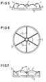
- Figures 6 and 7 show the top view and the side view of a ring-shaped sound transducer, the curvatures of the piezopolymer film 1 being formed as circular segments delimited by the webs 2 and the edge clamping 3, so that the curvature radius of the piezopolymer film 1 continuously increases with increasing distance from the geometric center of the transducer grows.
- the sections of the maximum transducer sensitivity also shift towards the outside as the frequency decreases.
- the ratio of the apparent transducer diameter to the sound wavelength in the surrounding medium therefore remains approximately constant. This causes an opening angle that is independent of the frequency.
- the curvatures can also be arranged at an angle to the direction of radiation. In the case shown, the angles of all apex lines with respect to the main emission direction are of the same size and less than 90 °. In this way, the sound signal is focused on a predetermined point in the main beam direction.
- a large bandwidth of the transducer results from the superposition of the sound pressure amplitudes of geometrically different individual elements with different band center frequencies.
- the radiation characteristic of the transducer can be adjusted over a wide range by varying the geometrical position of the individual curvatures with respect to one another. A wide range is a prerequisite for the effective use of digital signal processing methods for ultrasonic signals for acoustic object identification.
Landscapes
- Engineering & Computer Science (AREA)
- Mechanical Engineering (AREA)
- Transducers For Ultrasonic Waves (AREA)
Applications Claiming Priority (2)
| Application Number | Priority Date | Filing Date | Title |
|---|---|---|---|
| DE4209374 | 1992-03-23 | ||
| DE19924209374 DE4209374C2 (de) | 1992-03-23 | 1992-03-23 | Luftultraschallwandler |
Publications (1)
| Publication Number | Publication Date |
|---|---|
| EP0562326A1 true EP0562326A1 (fr) | 1993-09-29 |
Family
ID=6454785
Family Applications (1)
| Application Number | Title | Priority Date | Filing Date |
|---|---|---|---|
| EP93103482A Withdrawn EP0562326A1 (fr) | 1992-03-23 | 1993-03-04 | Transducteur ultrasonore atmosphérique |
Country Status (2)
| Country | Link |
|---|---|
| EP (1) | EP0562326A1 (fr) |
| DE (1) | DE4209374C2 (fr) |
Cited By (2)
| Publication number | Priority date | Publication date | Assignee | Title |
|---|---|---|---|---|
| WO2004016311A3 (fr) * | 2002-07-22 | 2004-05-06 | Hans-Werner Bender | Dispositif d'application d'ultrasons destine a ameliorer les conditions de traitement |
| CN103785603A (zh) * | 2012-10-31 | 2014-05-14 | 财团法人工业技术研究院 | 可挠式超声波致动装置 |
Families Citing this family (1)
| Publication number | Priority date | Publication date | Assignee | Title |
|---|---|---|---|---|
| DE10347021A1 (de) * | 2003-10-07 | 2005-05-04 | Werma Signaltechnik Gmbh & Co | Kalotte für einen Signalgeber |
Citations (3)
| Publication number | Priority date | Publication date | Assignee | Title |
|---|---|---|---|---|
| FR2465387A1 (fr) * | 1979-09-12 | 1981-03-20 | Audax | Transducteur piezoelectrique |
| GB1593273A (en) * | 1977-09-13 | 1981-07-15 | Standard Telephones Cables Ltd | Electro-acoustic transducers |
| DE3009068A1 (de) * | 1980-03-10 | 1981-09-24 | Reinhard Dipl.-Ing. Lerch | Piezopolymer-wandler mit fester membranunterstuetzung |
Family Cites Families (5)
| Publication number | Priority date | Publication date | Assignee | Title |
|---|---|---|---|---|
| DE1967130C2 (de) * | 1968-01-25 | 1982-04-01 | Pioneer Electronic Corp., Tokyo | Mechanisch-elektrisch bzw. elektrisch-mechanischer Wandler |
| JPS5215972B2 (fr) * | 1974-02-28 | 1977-05-06 | ||
| US4395652A (en) * | 1979-09-13 | 1983-07-26 | Toray Industries, Inc. | Ultrasonic transducer element |
| US4460841A (en) * | 1982-02-16 | 1984-07-17 | General Electric Company | Ultrasonic transducer shading |
| DD224503A1 (de) * | 1984-02-06 | 1985-07-10 | Karl Marx Stadt Tech Hochschul | Ultraschallpiezofoliensender mit ausgepraegter richtcharakteristik |
-
1992
- 1992-03-23 DE DE19924209374 patent/DE4209374C2/de not_active Expired - Fee Related
-
1993
- 1993-03-04 EP EP93103482A patent/EP0562326A1/fr not_active Withdrawn
Patent Citations (3)
| Publication number | Priority date | Publication date | Assignee | Title |
|---|---|---|---|---|
| GB1593273A (en) * | 1977-09-13 | 1981-07-15 | Standard Telephones Cables Ltd | Electro-acoustic transducers |
| FR2465387A1 (fr) * | 1979-09-12 | 1981-03-20 | Audax | Transducteur piezoelectrique |
| DE3009068A1 (de) * | 1980-03-10 | 1981-09-24 | Reinhard Dipl.-Ing. Lerch | Piezopolymer-wandler mit fester membranunterstuetzung |
Non-Patent Citations (1)
| Title |
|---|
| PATENT ABSTRACTS OF JAPAN vol. 10, no. 363 (E-461)(2420) 5. Dezember 1986 & JP-A-61 158 300 ( SONY CORP. ) 17. Juli 1986 * |
Cited By (2)
| Publication number | Priority date | Publication date | Assignee | Title |
|---|---|---|---|---|
| WO2004016311A3 (fr) * | 2002-07-22 | 2004-05-06 | Hans-Werner Bender | Dispositif d'application d'ultrasons destine a ameliorer les conditions de traitement |
| CN103785603A (zh) * | 2012-10-31 | 2014-05-14 | 财团法人工业技术研究院 | 可挠式超声波致动装置 |
Also Published As
| Publication number | Publication date |
|---|---|
| DE4209374C2 (de) | 1994-04-28 |
| DE4209374A1 (de) | 1993-09-30 |
Similar Documents
| Publication | Publication Date | Title |
|---|---|---|
| DE69120735T2 (de) | Fester Ursprung eines zweiflächigen Ultraschallwandlers | |
| DE3214789C2 (fr) | ||
| EP0383972B1 (fr) | Transducteur ultrasonore à éléments de vibration trapézoidaux, et procédé et dispositif pour leur fabrication | |
| EP0025092B1 (fr) | Transducteur ultrasonore et procédé pour sa fabrication | |
| EP0268818B1 (fr) | Dispositif pour l'émission et la réception de signaux ultrasonores | |
| DE68924057T2 (de) | Anordnung von Ultraschallwandlern. | |
| DE3932967C2 (fr) | ||
| DE69635308T2 (de) | Piezoelektrischer wandler | |
| DE4438672C2 (de) | Ultraschallabbildungssystem mit phasengesteuertem Array und dynamischer Höhenfokussierung | |
| DE3331955C2 (de) | Ultraschallwandler | |
| DE69506131T2 (de) | Akustischer richtwandler | |
| DE1132593B (de) | Akustisch wirksame Platte, insbesondere zur Ankopplung an einen elektroakustischen Wandler | |
| DE3689736T2 (de) | Ultraschall-Abbildungsgerät. | |
| DE3733776A1 (de) | Ultraschallsonde | |
| DE3812244C1 (fr) | ||
| DE10139160B4 (de) | Sensorarray und Sende-Empfangs-Gerät | |
| DE3732412A1 (de) | Ultraschallwandler mit astigmatischer sende-/empfangscharakteristik | |
| DE3102151C2 (fr) | ||
| EP0229981B1 (fr) | Procédé pour contrôler les caractéristiques du foyer d'un champ ultrasonique et dispositif de sa mise en oeuvre | |
| DE4236255C2 (de) | Akustische Linse | |
| DE4428500C2 (de) | Ultraschallwandlerarray mit einer reduzierten Anzahl von Wandlerelementen | |
| WO2007115625A2 (fr) | Convertisseur électroacoustique | |
| EP0562326A1 (fr) | Transducteur ultrasonore atmosphérique | |
| DE1762509A1 (de) | Piezoelektrischer Wandler | |
| EP1145772B1 (fr) | Transducteur ultrasonore et procédé de production d'un transducteur ultrasonore |
Legal Events
| Date | Code | Title | Description |
|---|---|---|---|
| PUAI | Public reference made under article 153(3) epc to a published international application that has entered the european phase |
Free format text: ORIGINAL CODE: 0009012 |
|
| AK | Designated contracting states |
Kind code of ref document: A1 Designated state(s): DE FR GB IT NL |
|
| 17P | Request for examination filed |
Effective date: 19940322 |
|
| 17Q | First examination report despatched |
Effective date: 19941125 |
|
| 18D | Application deemed to be withdrawn |
Effective date: 19950406 |