EP0562335A1 - Verrou pour la fixation amovible d'une prothèse dentaire - Google Patents
Verrou pour la fixation amovible d'une prothèse dentaire Download PDFInfo
- Publication number
- EP0562335A1 EP0562335A1 EP93103617A EP93103617A EP0562335A1 EP 0562335 A1 EP0562335 A1 EP 0562335A1 EP 93103617 A EP93103617 A EP 93103617A EP 93103617 A EP93103617 A EP 93103617A EP 0562335 A1 EP0562335 A1 EP 0562335A1
- Authority
- EP
- European Patent Office
- Prior art keywords
- bolt
- friction element
- latch according
- locking body
- closed position
- Prior art date
- Legal status (The legal status is an assumption and is not a legal conclusion. Google has not performed a legal analysis and makes no representation as to the accuracy of the status listed.)
- Granted
Links
Images


Classifications
-
- A—HUMAN NECESSITIES
- A61—MEDICAL OR VETERINARY SCIENCE; HYGIENE
- A61C—DENTISTRY; APPARATUS OR METHODS FOR ORAL OR DENTAL HYGIENE
- A61C13/00—Dental prostheses; Making same
- A61C13/225—Fastening prostheses in the mouth
- A61C13/273—Fastening prostheses in the mouth removably secured to residual teeth by using bolts or locks
Definitions
- the invention relates to a latch for releasably fastening dental prosthetic items to one another, which is pivotally arranged on one dental prosthetic item and engages in the recess in a recess of the other dental prosthetic item, with a friction element which, at least in the closed position of the latch, has an opposing frictional force generated on one and / or other dental prosthesis.
- Such a bolt is known for example from DE 35 04 162 C2 or DE 35 27 936 A1.
- the friction element in these known bolts is formed by a spring member, which in a preferred embodiment consists of a resilient tongue.
- This spring member protrudes over a surface of the locking body running parallel to the adjustment plane and is resiliently biased such that it rests on the upper or lower surface of the recess in the closed position of the locking bar.
- spring members or resilient tongues can also be provided.
- the spring force is essentially not adjustable.
- the spring force In order to obtain a secure locking of the bolt, however, the spring force must be adapted as precisely as possible to the individual dental prostheses that are made within the dentition depending on the chosen location. Because of the manufacturing tolerances that cannot be completely ruled out, an individual adjustability of the spring force is required.
- the setting of the spring force is only possible during the manufacturing process, since the spring force results from the design and geometry of the spring element or the spring tongue.
- a subsequent change and adjustment of the spring force - especially if it has decreased due to the situation described above - is not possible with the known bolt. This would mean a change in the design and geometry of the spring member, which is out of the question due to the high cost.
- it When it is designed as a spring tongue, it is conceivable to bend it accordingly to increase the spring force, but there is always the risk of breaking off, so that such a type of spring force readjustment is practically impossible.
- the friction element is arranged as a separate part on the body of the bolt and is in engagement with it in such a way that it can be displaced angularly with respect to at least one surface of the bolt body and can be fixed in any position is.
- the invention offers the advantage that the frictional force set in the aforementioned manner remains essentially constant over the entire period of use.
- the friction element is in engagement with the locking body in such a way that it can be fixed in any position. Accordingly, the invention has created a latch which can be adapted to any individual application and which closes reliably.
- the friction element is to directly generate the frictional force on one and / or other dental prosthetic item, it protrudes at least a little from a surface of the locking body in at least one sliding position, so that it has one end in contact with the one and for generating the frictional force / or other dental prosthesis.
- the friction element is preferably seated in a recess formed in the locking body, as a result of which it is accommodated in a space-saving manner.
- a particularly good fixable arrangement of the friction element on the bolt body results when the friction element is in clamping engagement with the bolt body.
- the friction element can consist, for example, of a pin which is arranged to be displaceable in the axial direction.
- the friction element can consist of a screw which is seated in a threaded bore formed in the locking body.
- a friction element designed in this way can be shifted or adjusted particularly simply and at the same time, and is at the same time fixed in every position against undesired shifting, so that a particularly precise adjustment of the frictional force can be achieved in this embodiment.
- a further development of this embodiment is characterized in that the threaded bore is formed by a through-hole connecting two opposite surfaces of the bolt body and the screw is in the manner of a grub screw, the head of which is located within the threaded bore and the opposite free end of which in the closed position of the bolt from the Threaded hole protrudes, which results in a particularly space-saving arrangement of the screw on or in the bolt body.
- the friction element acts on a plate which is fastened or articulated on one side to the bolt body and which, at least in the closed position of the bolt, is in frictional contact with one and / or another tooth replacement part.
- the frictional force is distributed over a particularly large area and thus has a greater effect.
- the plate projects from at least one sliding position of the friction element from a surface of the locking body. A particularly space-saving arrangement of the plate results from the fact that it sits in a recess formed in the locking body.
- the friction element can be displaced essentially parallel to the pivot axis of the bolt, as a result of which a particularly good friction effect is achieved.
- the friction element can expediently be arranged on the flat part, and preferably essentially between a projecting nose and the actuating part.
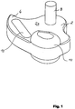
- the bolt shown there has a flat part 2 which has a projecting nose 4 which is used for the actual locking.
- a hole 6 is formed in the flat part 2 in the area outside the projecting nose 4, through which a hinge pin 8 is inserted.
- the bolt shown has a bead-like actuating part 10, which is provided with a grip notch.
- the latch is used for the detachable fastening of dental prostheses to one another.
- the tooth replacement parts can e.g. consist of crowns, bridges or partial prostheses, which is generally formed by a metallic primary part and a secondary part also made of metal.
- the bolt with its hinge pin 8 is generally pivotally mounted horizontally on the secondary part.
- the primary part has a recess, the shape of which essentially corresponds to the shape of the front section of the flat part 2 with the nose 4.
- the secondary part is provided with an opening through which the bolt with its flat part 2 extends. Bores are provided above and below this opening for receiving the hinge pin 8.
- the latch engages with its nose 6 in the aforementioned recess in the primary part.
- the latch is generally flush with the outside of the secondary part. Only the actuating part 10 protrudes a little so that it can be gripped more easily for pivoting the bolt.
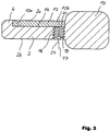
- An elongated friction plate 12 is provided in the closed position between the bolt and the inner surface (s) of the recess in the primary part and / or the opening in the secondary part, which counteracts undesired adjustment (see FIGS. 1 and 3 ), which is brought with its outer surface into a friction-generating system on an inner surface of the recess.
- the elongated Platelet 12 sits in a corresponding recess 14 which is formed on the upper side 2a of the flat part 2 and extends from the bead-like actuating part 10 into the projecting nose 4, as can be seen in particular in FIGS. 2 and 3.
- the plate 12 is articulated to the flat part 2 with its end 12a projecting into the nose 4 of the flat part 2 or - for example by soldering - is fastened and can be pivoted with respect to the flat part 2 with its opposite end 12b.
- a threaded bore 16 adjoins the end of the recess 14 adjacent the bead-like actuating part 10, which connects the bottom of the recess 14 to the underside 2b of the flat part 2.
- the threaded bore 16 is arranged with its axis 17 parallel to the axis of the bore 6 and the hinge pin 8 and thus to the pivot axis of the bolt.
- a grub screw 18 In the threaded bore 16 is a grub screw 18, the length of which corresponds approximately to the length of the threaded bore 16 and thus the thickness of the flat part 2 between its underside 2b and the recess 14.
- the screw 18 sits in the threaded bore 16 such that its head with the slot 20 faces the underside 2b of the flat part 2 (see FIG. 4), while the opposite end 22 of the screw 18 faces the recess 14 and thus the one seated therein Platelet 12 extends (see FIG. 3).
- the screw 18 serves to generate the required frictional force and thus as a friction element which ensures sufficient friction between the bolt in its closed position and the primary part and / or secondary part.
- the screw 18 also has a certain spring action, provided that it consists of an elastic material, which can also be metal, for example.
- the plate 12 can be omitted and the screw 18 protrudes with its free end 22 from the top 2a of the flat part 2 and directly in friction with the recess in the primary part and / or the opening in Secondary part can be brought.
- an axially displaceable pin or another friction element instead of the screw 18, which is in engagement with the flat part 2 of the bolt in such a way that it - like the screw 18 - is displaceable in the longitudinal direction and can be fixed in any position relative to the bolt.
- the direction of movement of the friction element runs parallel to the pivot axis of the bolt, provided that it is directed at an angle to a surface of the bolt, so that frictional pressure is generated on an inner surface of the recess in the primary part and / or the opening in the secondary part can.
Landscapes
- Health & Medical Sciences (AREA)
- Oral & Maxillofacial Surgery (AREA)
- Dentistry (AREA)
- Epidemiology (AREA)
- Life Sciences & Earth Sciences (AREA)
- Animal Behavior & Ethology (AREA)
- General Health & Medical Sciences (AREA)
- Public Health (AREA)
- Veterinary Medicine (AREA)
- Dental Prosthetics (AREA)
Applications Claiming Priority (2)
| Application Number | Priority Date | Filing Date | Title |
|---|---|---|---|
| DE4209421 | 1992-03-24 | ||
| DE4209421A DE4209421C1 (fr) | 1992-03-24 | 1992-03-24 |
Publications (2)
| Publication Number | Publication Date |
|---|---|
| EP0562335A1 true EP0562335A1 (fr) | 1993-09-29 |
| EP0562335B1 EP0562335B1 (fr) | 1997-06-11 |
Family
ID=6454810
Family Applications (1)
| Application Number | Title | Priority Date | Filing Date |
|---|---|---|---|
| EP93103617A Expired - Lifetime EP0562335B1 (fr) | 1992-03-24 | 1993-03-06 | Verrou pour la fixation amovible d'une prothèse dentaire |
Country Status (2)
| Country | Link |
|---|---|
| EP (1) | EP0562335B1 (fr) |
| DE (2) | DE4209421C1 (fr) |
Families Citing this family (2)
| Publication number | Priority date | Publication date | Assignee | Title |
|---|---|---|---|---|
| DE102005016642A1 (de) | 2004-06-30 | 2006-02-02 | Günter Rübeling Zahntechnisches Laboratorium GmbH & Co. KG | Vorrichtung zur lösbaren Befestigung von Zahnersatzteilen, Zahnersatzteil mit einer solchen Vorrichtung sowie Verfahren zur Montage eines Riegels an einem Zahnersatzteil |
| DE102006050690A1 (de) | 2006-10-24 | 2008-04-30 | Dentacon Gmbh Medizin- Und Dentaltechnik | Vorrichtung zur lösbaren Befestigung eines Zahnersatzes |
Citations (5)
| Publication number | Priority date | Publication date | Assignee | Title |
|---|---|---|---|---|
| US1765851A (en) * | 1928-08-16 | 1930-06-24 | Annie Richardson | Adjustable attachment for dentures |
| DE3312908A1 (de) * | 1982-06-16 | 1983-12-29 | Gäßler GmbH & Co KG, 7900 Ulm | Verriegelung zur loesbaren befestigung einer zahnprothese |
| DE8517417U1 (de) * | 1985-06-14 | 1985-08-01 | Janzen, Klaus-Werner, 5800 Hagen | Geschiebe für klammerlose Zahnprothesen |
| EP0254027A2 (fr) * | 1986-06-20 | 1988-01-27 | Nova-Pro Attachment GmbH | Attelage coulissant pour prothèse dentaire |
| EP0270108A2 (fr) * | 1986-12-04 | 1988-06-08 | Nova-Pro Attachment GmbH | Couronne à dispositif d'ancrage |
Family Cites Families (2)
| Publication number | Priority date | Publication date | Assignee | Title |
|---|---|---|---|---|
| DE3504162A1 (de) * | 1985-02-07 | 1986-08-14 | Karl-Heinz 7910 Neu-Ulm Staub | Riegel zur loesbaren befestigung einer zahnprothese |
| DE3527936A1 (de) * | 1985-02-07 | 1987-02-12 | Karl-Heinz Staub | Riegel zur loesbaren befestigung einer zahnprothese |
-
1992
- 1992-03-24 DE DE4209421A patent/DE4209421C1/de not_active Expired - Lifetime
-
1993
- 1993-03-06 EP EP93103617A patent/EP0562335B1/fr not_active Expired - Lifetime
- 1993-03-06 DE DE59306709T patent/DE59306709D1/de not_active Expired - Fee Related
Patent Citations (5)
| Publication number | Priority date | Publication date | Assignee | Title |
|---|---|---|---|---|
| US1765851A (en) * | 1928-08-16 | 1930-06-24 | Annie Richardson | Adjustable attachment for dentures |
| DE3312908A1 (de) * | 1982-06-16 | 1983-12-29 | Gäßler GmbH & Co KG, 7900 Ulm | Verriegelung zur loesbaren befestigung einer zahnprothese |
| DE8517417U1 (de) * | 1985-06-14 | 1985-08-01 | Janzen, Klaus-Werner, 5800 Hagen | Geschiebe für klammerlose Zahnprothesen |
| EP0254027A2 (fr) * | 1986-06-20 | 1988-01-27 | Nova-Pro Attachment GmbH | Attelage coulissant pour prothèse dentaire |
| EP0270108A2 (fr) * | 1986-12-04 | 1988-06-08 | Nova-Pro Attachment GmbH | Couronne à dispositif d'ancrage |
Also Published As
| Publication number | Publication date |
|---|---|
| EP0562335B1 (fr) | 1997-06-11 |
| DE59306709D1 (de) | 1997-07-17 |
| DE4209421C1 (fr) | 1993-09-02 |
Similar Documents
| Publication | Publication Date | Title |
|---|---|---|
| DE3687293T2 (de) | Vollstaendig gegliederte lagerungsvorrichtung. | |
| EP0627507B1 (fr) | Machine de cardage avec chapeaux mobiles | |
| EP0371153B1 (fr) | Elément de connexion | |
| DE3445885A1 (de) | Scharnier | |
| DE2433358C2 (de) | Dentaltechnisches Geschiebe zur lösbaren Befestigung von Zahnprothesen am Restgebiß | |
| EP0575570B1 (fr) | Montre-bracelet | |
| DE19619786C2 (de) | Geschiebe | |
| DE2657628A1 (de) | Moebelscharnier | |
| DE3786568T2 (de) | Scharniervorrichtung, insbesondere für Brillen. | |
| EP0562335B1 (fr) | Verrou pour la fixation amovible d'une prothèse dentaire | |
| DE2817768C3 (de) | Geländer oder dergleichen | |
| DE29701545U1 (de) | Befestigungsanordnung für einen Toilettensitz | |
| DE4323939C2 (de) | Gelenkvorrichtung, insbesondere für Drehkipptür oder -fenster | |
| DE4029147C1 (en) | Dental bridge or crown connection - incorporates locking bar with slit at right-angles to its pivot plane | |
| DE3421970A1 (de) | Vorrichtung zum befestigen eines abnehmbaren zahnprothesenteiles | |
| AT413184B (de) | Vorrichtung für die neigungs-verstellung von schubladen-frontblenden | |
| DE4447057C2 (de) | Knochenimplantat mit verstellbarem Zusatzelement | |
| DE19611354C2 (de) | Vorrichtung zum Halten eines herausnehmbaren Zahnersatzes an einem festsitzenden Zahnersatz | |
| DE3538727A1 (de) | Zapfenband fuer moebel | |
| DE2632695C2 (de) | Ausgleichsbuchse für die Befestigung von Griffen od.dgl. | |
| DE2549727B2 (de) | Kunststoff-Möbelbeschlagteil | |
| DE7309253U (de) | Vorrichtung zum laengeneinstellbaren verbinden von schubstangen und/oder schubgliedern eines beschlages fuer ein fenster eine tuer od.dgl. | |
| AT390379B (de) | Sohlenauflageplatte fuer skibindungen | |
| DE19646023C1 (de) | Dentale Verankerung | |
| EP1611866A1 (fr) | Attachement pour prothèse dentaire, prothèse dentaire avec attachement et methode pour monter un attachement dans une prothèse dentaire |
Legal Events
| Date | Code | Title | Description |
|---|---|---|---|
| PUAI | Public reference made under article 153(3) epc to a published international application that has entered the european phase |
Free format text: ORIGINAL CODE: 0009012 |
|
| AK | Designated contracting states |
Kind code of ref document: A1 Designated state(s): DE FR IT |
|
| 17P | Request for examination filed |
Effective date: 19930916 |
|
| 17Q | First examination report despatched |
Effective date: 19960102 |
|
| GRAG | Despatch of communication of intention to grant |
Free format text: ORIGINAL CODE: EPIDOS AGRA |
|
| GRAH | Despatch of communication of intention to grant a patent |
Free format text: ORIGINAL CODE: EPIDOS IGRA |
|
| GRAH | Despatch of communication of intention to grant a patent |
Free format text: ORIGINAL CODE: EPIDOS IGRA |
|
| GRAA | (expected) grant |
Free format text: ORIGINAL CODE: 0009210 |
|
| AK | Designated contracting states |
Kind code of ref document: B1 Designated state(s): DE FR IT |
|
| PG25 | Lapsed in a contracting state [announced via postgrant information from national office to epo] |
Ref country code: FR Effective date: 19970611 |
|
| REF | Corresponds to: |
Ref document number: 59306709 Country of ref document: DE Date of ref document: 19970717 |
|
| EN | Fr: translation not filed | ||
| PLBE | No opposition filed within time limit |
Free format text: ORIGINAL CODE: 0009261 |
|
| 26N | No opposition filed | ||
| PG25 | Lapsed in a contracting state [announced via postgrant information from national office to epo] |
Ref country code: IT Free format text: LAPSE BECAUSE OF NON-PAYMENT OF DUE FEES;WARNING: LAPSES OF ITALIAN PATENTS WITH EFFECTIVE DATE BEFORE 2007 MAY HAVE OCCURRED AT ANY TIME BEFORE 2007. THE CORRECT EFFECTIVE DATE MAY BE DIFFERENT FROM THE ONE RECORDED. Effective date: 20050306 |
|
| PGFP | Annual fee paid to national office [announced via postgrant information from national office to epo] |
Ref country code: DE Payment date: 20060404 Year of fee payment: 14 |
|
| PG25 | Lapsed in a contracting state [announced via postgrant information from national office to epo] |
Ref country code: DE Free format text: LAPSE BECAUSE OF NON-PAYMENT OF DUE FEES Effective date: 20071002 |