EP0562348A1 - Dispositif de fixation d'objets allongés à un support - Google Patents
Dispositif de fixation d'objets allongés à un support Download PDFInfo
- Publication number
- EP0562348A1 EP0562348A1 EP93103726A EP93103726A EP0562348A1 EP 0562348 A1 EP0562348 A1 EP 0562348A1 EP 93103726 A EP93103726 A EP 93103726A EP 93103726 A EP93103726 A EP 93103726A EP 0562348 A1 EP0562348 A1 EP 0562348A1
- Authority
- EP
- European Patent Office
- Prior art keywords
- clamp
- legs
- base
- strand
- fastening part
- Prior art date
- Legal status (The legal status is an assumption and is not a legal conclusion. Google has not performed a legal analysis and makes no representation as to the accuracy of the status listed.)
- Granted
Links
Images
Classifications
-
- F—MECHANICAL ENGINEERING; LIGHTING; HEATING; WEAPONS; BLASTING
- F16—ENGINEERING ELEMENTS AND UNITS; GENERAL MEASURES FOR PRODUCING AND MAINTAINING EFFECTIVE FUNCTIONING OF MACHINES OR INSTALLATIONS; THERMAL INSULATION IN GENERAL
- F16L—PIPES; JOINTS OR FITTINGS FOR PIPES; SUPPORTS FOR PIPES, CABLES OR PROTECTIVE TUBING; MEANS FOR THERMAL INSULATION IN GENERAL
- F16L3/00—Supports for pipes, cables or protective tubing, e.g. hangers, holders, clamps, cleats, clips, brackets
- F16L3/08—Supports for pipes, cables or protective tubing, e.g. hangers, holders, clamps, cleats, clips, brackets substantially surrounding the pipe, cable or protective tubing
- F16L3/10—Supports for pipes, cables or protective tubing, e.g. hangers, holders, clamps, cleats, clips, brackets substantially surrounding the pipe, cable or protective tubing divided, i.e. with two members engaging the pipe, cable or protective tubing
- F16L3/1075—Supports for pipes, cables or protective tubing, e.g. hangers, holders, clamps, cleats, clips, brackets substantially surrounding the pipe, cable or protective tubing divided, i.e. with two members engaging the pipe, cable or protective tubing with two members, the two members being joined with a hinge on one side and fastened together on the other side
-
- F—MECHANICAL ENGINEERING; LIGHTING; HEATING; WEAPONS; BLASTING
- F16—ENGINEERING ELEMENTS AND UNITS; GENERAL MEASURES FOR PRODUCING AND MAINTAINING EFFECTIVE FUNCTIONING OF MACHINES OR INSTALLATIONS; THERMAL INSULATION IN GENERAL
- F16L—PIPES; JOINTS OR FITTINGS FOR PIPES; SUPPORTS FOR PIPES, CABLES OR PROTECTIVE TUBING; MEANS FOR THERMAL INSULATION IN GENERAL
- F16L3/00—Supports for pipes, cables or protective tubing, e.g. hangers, holders, clamps, cleats, clips, brackets
- F16L3/08—Supports for pipes, cables or protective tubing, e.g. hangers, holders, clamps, cleats, clips, brackets substantially surrounding the pipe, cable or protective tubing
- F16L3/10—Supports for pipes, cables or protective tubing, e.g. hangers, holders, clamps, cleats, clips, brackets substantially surrounding the pipe, cable or protective tubing divided, i.e. with two members engaging the pipe, cable or protective tubing
- F16L3/1066—Supports for pipes, cables or protective tubing, e.g. hangers, holders, clamps, cleats, clips, brackets substantially surrounding the pipe, cable or protective tubing divided, i.e. with two members engaging the pipe, cable or protective tubing with three or more members surrounding the pipe
Definitions
- the invention relates to a device for fastening a strand-shaped object to a base, consisting of a metallic clamp, which has a fastening part for fixing it to the base, two legs connected in one piece to the fastening part and separated from one another by an intermediate space for receiving the strand-shaped object and has a lock for locking the free ends of the two legs (DE-GM 78 37 479).
- the “Strand-shaped objects” which are to be fastened with this device are cables and pipes of all kinds.
- the "pipe” is taken into account below for all possible applications.
- the base to which the pipe is to be attached can be a wall, a mast or any load-bearing structure.
- the mounting clamps previously known for this purpose are designed and assembled in a complex manner. The fixing of the pipe in the clamps is often difficult.
- the known device according to the aforementioned DE-GM 78 37 479 is used to attach an electrical waveguide to a mast.
- an insert made of elastic material is also used in this device.
- the clamp itself consists of a mechanically stable part and a part that can be connected to it and deformed within limits. Both parts of the Clamps are closed and clamped together using a screw that is to be attached to the free ends of the clamps.
- This known device consists of four parts including the insert.
- the clamp itself has three parts that have to be assembled when it is assembled. Their handling is therefore very complex, which is particularly noticeable at unfavorable installation locations. The assembly of a clamp consisting of several parts is often troublesome, for example on masts.
- the invention has for its object to significantly simplify the above-described device in terms of structure and handling.
- This device consists of a one-piece clamp with the captive bracket attached as a closure element. It is therefore simple to set up and easy to assemble. The attachment of the tube in the clamp is also facilitated, since only the two legs of the clamp made of spring steel need to be pressed apart. They spring back in the direction of their starting position when the pipe lies in the space provided. The pipe is then already held relatively firmly, since the two legs, given the correct dimensioning of the clamp, lie firmly against the surface of the pipe because of their resilient properties. The clamp is then closed with the bracket. To do this, only the free ends of the two legs need to be pressed together until the bracket attached to one leg can be snapped over the other.
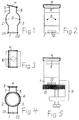
- the substantially U-shaped clamp shown in Fig. 1 is made of spring steel. It has a fastening part 1 for fixing it to a base and two legs 2 and 3 connected in one piece to the fastening part. At the free end of the leg 3, a bracket 4 is pivotally but captively attached. At the free end of the leg 2 there is an offset 5 pointing in the direction away from the leg 3.
- the two legs 2 and 3 are separated from each other by a space so that a pipe 6 to be enclosed (FIG. 4) can be accommodated therein.
- the middle region of the legs 2 and 3 is also bulged.
- the bulged area of the legs 2 and 3 is adapted as well as possible to the cross-sectional shape of the object to be enclosed.
- the bulge for receiving the tube 6, which has a circular cross section is made round.
- projections 9 can be attached in the region of the bulges, which protrusions may press into the surface of the enclosed tube 6 if the outer layer is soft enough. An improved hold of the tube 6 in the clamp can thereby be achieved.
- a through hole 10 can be made in the fastening part 1 of the clamp.
- the clamp can then be screwed onto a base, for example by means of a screw. 5 can also be used for the fastening of the clamp, which can be inserted into the fastening part 1 of the clamp.
- openings 12 can be made in the fastening part 1 of the clamp, into which corresponding projections of the mounting clamp 11 engage in the working position.
Landscapes
- Engineering & Computer Science (AREA)
- General Engineering & Computer Science (AREA)
- Mechanical Engineering (AREA)
- Clamps And Clips (AREA)
- Mutual Connection Of Rods And Tubes (AREA)
Applications Claiming Priority (2)
| Application Number | Priority Date | Filing Date | Title |
|---|---|---|---|
| DE4208791A DE4208791A1 (de) | 1992-03-19 | 1992-03-19 | Vorrichtung zur befestigung eines strangfoermigen gegenstandes an einer unterlage |
| DE4208791 | 1992-03-19 |
Publications (2)
| Publication Number | Publication Date |
|---|---|
| EP0562348A1 true EP0562348A1 (fr) | 1993-09-29 |
| EP0562348B1 EP0562348B1 (fr) | 1995-08-02 |
Family
ID=6454434
Family Applications (1)
| Application Number | Title | Priority Date | Filing Date |
|---|---|---|---|
| EP93103726A Expired - Lifetime EP0562348B1 (fr) | 1992-03-19 | 1993-03-09 | Dispositif de fixation d'objets allongés à un support |
Country Status (2)
| Country | Link |
|---|---|
| EP (1) | EP0562348B1 (fr) |
| DE (2) | DE4208791A1 (fr) |
Cited By (2)
| Publication number | Priority date | Publication date | Assignee | Title |
|---|---|---|---|---|
| DE19746121A1 (de) * | 1997-10-18 | 1999-04-22 | Cit Alcatel | Vorrichtung zur Befestigung eines strangförmigen Gegenstandes an einer Unterlage |
| WO2009004399A1 (fr) * | 2007-07-03 | 2009-01-08 | Alcatel-Lucent | Dispositif pour monter un composant tubulaire |
Families Citing this family (1)
| Publication number | Priority date | Publication date | Assignee | Title |
|---|---|---|---|---|
| DE9316777U1 (de) * | 1993-11-03 | 1993-12-16 | Kabelmetal Electro Gmbh, 30179 Hannover | Vorrichtung zur Befestigung von strangförmigen Gegenständen an einer Unterlage |
Citations (5)
| Publication number | Priority date | Publication date | Assignee | Title |
|---|---|---|---|---|
| US1963908A (en) * | 1932-07-19 | 1934-06-19 | Manasek Emil | Clamp |
| GB974002A (en) * | 1960-05-05 | 1964-11-04 | Sarmi S A | Improvements in or relating to supporting clips |
| FR1477777A (fr) * | 1966-03-12 | 1967-04-21 | Metal Usine Soc Ind Du | Collier de serrage pour tubes ou objets similaires |
| EP0010073A1 (fr) * | 1978-09-27 | 1980-04-16 | Negurosu Electrical Industries Co., Ltd. | Un collier de serrage pour la fixation de tuyaux et analogues pour le montage sur des structures |
| DE3019303A1 (de) * | 1980-05-21 | 1981-11-26 | Sanha Kaimer Kg, 4300 Essen | Rohr-klips |
-
1992
- 1992-03-19 DE DE4208791A patent/DE4208791A1/de not_active Withdrawn
-
1993
- 1993-03-09 EP EP93103726A patent/EP0562348B1/fr not_active Expired - Lifetime
- 1993-03-09 DE DE59300421T patent/DE59300421D1/de not_active Expired - Lifetime
Patent Citations (5)
| Publication number | Priority date | Publication date | Assignee | Title |
|---|---|---|---|---|
| US1963908A (en) * | 1932-07-19 | 1934-06-19 | Manasek Emil | Clamp |
| GB974002A (en) * | 1960-05-05 | 1964-11-04 | Sarmi S A | Improvements in or relating to supporting clips |
| FR1477777A (fr) * | 1966-03-12 | 1967-04-21 | Metal Usine Soc Ind Du | Collier de serrage pour tubes ou objets similaires |
| EP0010073A1 (fr) * | 1978-09-27 | 1980-04-16 | Negurosu Electrical Industries Co., Ltd. | Un collier de serrage pour la fixation de tuyaux et analogues pour le montage sur des structures |
| DE3019303A1 (de) * | 1980-05-21 | 1981-11-26 | Sanha Kaimer Kg, 4300 Essen | Rohr-klips |
Cited By (2)
| Publication number | Priority date | Publication date | Assignee | Title |
|---|---|---|---|---|
| DE19746121A1 (de) * | 1997-10-18 | 1999-04-22 | Cit Alcatel | Vorrichtung zur Befestigung eines strangförmigen Gegenstandes an einer Unterlage |
| WO2009004399A1 (fr) * | 2007-07-03 | 2009-01-08 | Alcatel-Lucent | Dispositif pour monter un composant tubulaire |
Also Published As
| Publication number | Publication date |
|---|---|
| DE59300421D1 (de) | 1995-09-07 |
| DE4208791A1 (de) | 1993-09-23 |
| EP0562348B1 (fr) | 1995-08-02 |
Similar Documents
| Publication | Publication Date | Title |
|---|---|---|
| EP0508050B1 (fr) | Collier du support avec charniere | |
| DE2502050C3 (de) | Kabeldurchführung mit Zugentlastung | |
| EP0613225A1 (fr) | Entretoise pour fils conducteurs, notamment pour faisceaux de lignes électriques dans un avion | |
| DE3604291A1 (de) | Kabeldurchfuehrung | |
| DE19946890C2 (de) | Halteelement zur unverlierbaren Halterung von Kopfschrauben | |
| DE3023379A1 (de) | Befestigungsschelle | |
| EP0562348B1 (fr) | Dispositif de fixation d'objets allongés à un support | |
| DE102004032053B4 (de) | Rohrschelle mit integriertem Rast-Verschluss | |
| EP0927308A1 (fr) | Dispositif a crans pour element de construction a deplacement lineaire | |
| DE3014697C2 (de) | Kabelklemme, vorzugsweise für geschirmte Kabel | |
| DE102015002800B4 (de) | Schnappmutter | |
| DE19547231C2 (de) | Befestigungsvorrichtung für Kabelstecker | |
| DE10258454B4 (de) | Schelle | |
| EP0388663B1 (fr) | Collier pour tuyaux | |
| DE2622527C3 (de) | Kabelschelle für die Befestigung von Kabeln auf einer Unterlage | |
| DE3805257C2 (de) | Aufhängevorrichtung zum Befestigen einer Kabelmuffe an einem Tragseil | |
| DE2116577C3 (de) | Schelle zum Befestigen von Kabeln o.dgl. an Winkeleisen, insbesondere an winkeleisenförmig ausgebildeten Eckstücken von Gittermasten | |
| DE19746121A1 (de) | Vorrichtung zur Befestigung eines strangförmigen Gegenstandes an einer Unterlage | |
| EP0334972A1 (fr) | Connecteur électrique | |
| DE19748130A1 (de) | Zwingvorrichtung zum Spannen von Rundmaterialien | |
| DE2855632A1 (de) | Rohrklemme | |
| DE20109169U1 (de) | Winkelschleiferschutzhaube | |
| AT9411U1 (de) | Spange zur befestigung eines pflanzstabes an einem spanndraht | |
| DE2346506A1 (de) | Sicherungsunterteil zur befestigung auf stromschienen | |
| EP1705771A2 (fr) | Dispositif de traversée de câble |
Legal Events
| Date | Code | Title | Description |
|---|---|---|---|
| PUAI | Public reference made under article 153(3) epc to a published international application that has entered the european phase |
Free format text: ORIGINAL CODE: 0009012 |
|
| AK | Designated contracting states |
Kind code of ref document: A1 Designated state(s): DE FR GB IT |
|
| 17P | Request for examination filed |
Effective date: 19930826 |
|
| 17Q | First examination report despatched |
Effective date: 19940321 |
|
| GRAA | (expected) grant |
Free format text: ORIGINAL CODE: 0009210 |
|
| ITF | It: translation for a ep patent filed | ||
| AK | Designated contracting states |
Kind code of ref document: B1 Designated state(s): DE FR GB IT |
|
| REF | Corresponds to: |
Ref document number: 59300421 Country of ref document: DE Date of ref document: 19950907 |
|
| GBT | Gb: translation of ep patent filed (gb section 77(6)(a)/1977) |
Effective date: 19950821 |
|
| ET | Fr: translation filed | ||
| PLBE | No opposition filed within time limit |
Free format text: ORIGINAL CODE: 0009261 |
|
| 26N | No opposition filed | ||
| REG | Reference to a national code |
Ref country code: GB Ref legal event code: IF02 |
|
| PGFP | Annual fee paid to national office [announced via postgrant information from national office to epo] |
Ref country code: FR Payment date: 20120403 Year of fee payment: 20 |
|
| PGFP | Annual fee paid to national office [announced via postgrant information from national office to epo] |
Ref country code: DE Payment date: 20120323 Year of fee payment: 20 |
|
| PGFP | Annual fee paid to national office [announced via postgrant information from national office to epo] |
Ref country code: GB Payment date: 20120322 Year of fee payment: 20 |
|
| PGFP | Annual fee paid to national office [announced via postgrant information from national office to epo] |
Ref country code: IT Payment date: 20120329 Year of fee payment: 20 |
|
| REG | Reference to a national code |
Ref country code: DE Ref legal event code: R071 Ref document number: 59300421 Country of ref document: DE |
|
| REG | Reference to a national code |
Ref country code: GB Ref legal event code: PE20 Expiry date: 20130308 |
|
| PG25 | Lapsed in a contracting state [announced via postgrant information from national office to epo] |
Ref country code: DE Free format text: LAPSE BECAUSE OF EXPIRATION OF PROTECTION Effective date: 20130312 Ref country code: GB Free format text: LAPSE BECAUSE OF EXPIRATION OF PROTECTION Effective date: 20130308 |
|
| REG | Reference to a national code |
Ref country code: FR Ref legal event code: TP Owner name: ALCATEL, FR Effective date: 20130801 |
|
| REG | Reference to a national code |
Ref country code: FR Ref legal event code: GC Effective date: 20131126 |
|
| REG | Reference to a national code |
Ref country code: FR Ref legal event code: RG Effective date: 20141016 |