EP0562465B1 - Türschliesser mit kombiniertem Ventil für die Oeffnungsdämpfung und die Schliessgeschwindigkeit - Google Patents
Türschliesser mit kombiniertem Ventil für die Oeffnungsdämpfung und die Schliessgeschwindigkeit Download PDFInfo
- Publication number
- EP0562465B1 EP0562465B1 EP93104463A EP93104463A EP0562465B1 EP 0562465 B1 EP0562465 B1 EP 0562465B1 EP 93104463 A EP93104463 A EP 93104463A EP 93104463 A EP93104463 A EP 93104463A EP 0562465 B1 EP0562465 B1 EP 0562465B1
- Authority
- EP
- European Patent Office
- Prior art keywords
- door
- piston
- valve
- closer
- channel
- Prior art date
- Legal status (The legal status is an assumption and is not a legal conclusion. Google has not performed a legal analysis and makes no representation as to the accuracy of the status listed.)
- Expired - Lifetime
Links
Images


Classifications
-
- E—FIXED CONSTRUCTIONS
- E05—LOCKS; KEYS; WINDOW OR DOOR FITTINGS; SAFES
- E05F—DEVICES FOR MOVING WINGS INTO OPEN OR CLOSED POSITION; CHECKS FOR WINGS; WING FITTINGS NOT OTHERWISE PROVIDED FOR, CONCERNED WITH THE FUNCTIONING OF THE WING
- E05F3/00—Closers or openers with braking devices, e.g. checks; Construction of pneumatic or liquid braking devices
- E05F3/04—Closers or openers with braking devices, e.g. checks; Construction of pneumatic or liquid braking devices with liquid piston brakes
- E05F3/12—Special devices controlling the circulation of the liquid, e.g. valve arrangement
-
- E—FIXED CONSTRUCTIONS
- E05—LOCKS; KEYS; WINDOW OR DOOR FITTINGS; SAFES
- E05F—DEVICES FOR MOVING WINGS INTO OPEN OR CLOSED POSITION; CHECKS FOR WINGS; WING FITTINGS NOT OTHERWISE PROVIDED FOR, CONCERNED WITH THE FUNCTIONING OF THE WING
- E05F3/00—Closers or openers with braking devices, e.g. checks; Construction of pneumatic or liquid braking devices
- E05F3/04—Closers or openers with braking devices, e.g. checks; Construction of pneumatic or liquid braking devices with liquid piston brakes
- E05F3/10—Closers or openers with braking devices, e.g. checks; Construction of pneumatic or liquid braking devices with liquid piston brakes with a spring, other than a torsion spring, and a piston, the axes of which are the same or lie in the same direction
- E05F3/102—Closers or openers with braking devices, e.g. checks; Construction of pneumatic or liquid braking devices with liquid piston brakes with a spring, other than a torsion spring, and a piston, the axes of which are the same or lie in the same direction with rack-and-pinion transmission between driving shaft and piston within the closer housing
-
- E—FIXED CONSTRUCTIONS
- E05—LOCKS; KEYS; WINDOW OR DOOR FITTINGS; SAFES
- E05Y—INDEXING SCHEME ASSOCIATED WITH SUBCLASSES E05D AND E05F, RELATING TO CONSTRUCTION ELEMENTS, ELECTRIC CONTROL, POWER SUPPLY, POWER SIGNAL OR TRANSMISSION, USER INTERFACES, MOUNTING OR COUPLING, DETAILS, ACCESSORIES, AUXILIARY OPERATIONS NOT OTHERWISE PROVIDED FOR, APPLICATION THEREOF
- E05Y2201/00—Constructional elements; Accessories therefor
- E05Y2201/20—Brakes; Disengaging means; Holders; Stops; Valves; Accessories therefor
-
- E—FIXED CONSTRUCTIONS
- E05—LOCKS; KEYS; WINDOW OR DOOR FITTINGS; SAFES
- E05Y—INDEXING SCHEME ASSOCIATED WITH SUBCLASSES E05D AND E05F, RELATING TO CONSTRUCTION ELEMENTS, ELECTRIC CONTROL, POWER SUPPLY, POWER SIGNAL OR TRANSMISSION, USER INTERFACES, MOUNTING OR COUPLING, DETAILS, ACCESSORIES, AUXILIARY OPERATIONS NOT OTHERWISE PROVIDED FOR, APPLICATION THEREOF
- E05Y2201/00—Constructional elements; Accessories therefor
- E05Y2201/20—Brakes; Disengaging means; Holders; Stops; Valves; Accessories therefor
- E05Y2201/23—Actuation thereof
- E05Y2201/232—Actuation thereof by automatically acting means
-
- E—FIXED CONSTRUCTIONS
- E05—LOCKS; KEYS; WINDOW OR DOOR FITTINGS; SAFES
- E05Y—INDEXING SCHEME ASSOCIATED WITH SUBCLASSES E05D AND E05F, RELATING TO CONSTRUCTION ELEMENTS, ELECTRIC CONTROL, POWER SUPPLY, POWER SIGNAL OR TRANSMISSION, USER INTERFACES, MOUNTING OR COUPLING, DETAILS, ACCESSORIES, AUXILIARY OPERATIONS NOT OTHERWISE PROVIDED FOR, APPLICATION THEREOF
- E05Y2201/00—Constructional elements; Accessories therefor
- E05Y2201/20—Brakes; Disengaging means; Holders; Stops; Valves; Accessories therefor
- E05Y2201/252—Type of friction
- E05Y2201/254—Fluid or viscous friction
-
- E—FIXED CONSTRUCTIONS
- E05—LOCKS; KEYS; WINDOW OR DOOR FITTINGS; SAFES
- E05Y—INDEXING SCHEME ASSOCIATED WITH SUBCLASSES E05D AND E05F, RELATING TO CONSTRUCTION ELEMENTS, ELECTRIC CONTROL, POWER SUPPLY, POWER SIGNAL OR TRANSMISSION, USER INTERFACES, MOUNTING OR COUPLING, DETAILS, ACCESSORIES, AUXILIARY OPERATIONS NOT OTHERWISE PROVIDED FOR, APPLICATION THEREOF
- E05Y2201/00—Constructional elements; Accessories therefor
- E05Y2201/40—Motors; Magnets; Springs; Weights; Accessories therefor
- E05Y2201/43—Motors
- E05Y2201/448—Fluid motors; Details thereof
- E05Y2201/458—Valves
-
- E—FIXED CONSTRUCTIONS
- E05—LOCKS; KEYS; WINDOW OR DOOR FITTINGS; SAFES
- E05Y—INDEXING SCHEME ASSOCIATED WITH SUBCLASSES E05D AND E05F, RELATING TO CONSTRUCTION ELEMENTS, ELECTRIC CONTROL, POWER SUPPLY, POWER SIGNAL OR TRANSMISSION, USER INTERFACES, MOUNTING OR COUPLING, DETAILS, ACCESSORIES, AUXILIARY OPERATIONS NOT OTHERWISE PROVIDED FOR, APPLICATION THEREOF
- E05Y2900/00—Application of doors, windows, wings or fittings thereof
- E05Y2900/10—Application of doors, windows, wings or fittings thereof for buildings or parts thereof
- E05Y2900/13—Type of wing
- E05Y2900/132—Doors
Definitions
- the invention relates to a door closer, with an adjustable opening damping as an additional function is provided.
- a third flow channel with a third adjustable Valve activated to enable the so-called end stroke that is, the door with sufficient speed to drop in the lock.
- the main disadvantage of this is that a slowly opening door is braked exactly as a door that opens quickly.
- the throttle valve has however, the task of that when violently belated Doors dampening increased, with one slowly opening door reduces the damping or even is turned off.
- DE-A-2527607 shows a door closer with one valve each for closing damping, opening damping and a closing delay. Doing so Contamination of the closing delay valve avoided, by its valve seat from backflowing oil the opening damping is lifted off. From CH-A-514 062 and DE-C-533 818 door closers are known which only have an adjustable valve for closing damping; opening damping is not provided. A door closer is known from GB-A-2 156 950, at a thermostatic valve in a flow channel the closing damping determines. An opening damping is also not provided here.
- FR-A-2 323 857 shows a door closer with control rod and electrohydraulic blocking of the Open position but without opening damping.
- DE-A-1 806 002 shows a spring arrangement in a door closer without Opening damping.
- the invention is therefore based on the object to create a door closer that mentioned Does not have disadvantages, and which in particular easier to manufacture and easier to Is set, and at what valve contamination does not occur.
- the Valve can also at any point on the flow channel to be ordered. Because when operating the door closer only one valve for the functions mentioned to be set, the setting also becomes essential facilitated. It has been shown that with the same Valve one for both functions Setting value can be achieved, especially with one heavy door. Since the closing force (spring force) is increased, the valve must be closed somewhat to achieve the correct closing speed. This also makes the throttle gap of the opening damping reduced synchronously. That has again with the result that the opening damping is increased and is precisely adapted to the door weight.
- Valve contamination also comes in handy not open, as the valve opens and closes every time fluid flowed through from both sides becomes.
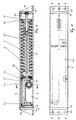
- Figure 1 shows a plan view of a Door closer 1 with a cuboid housing 21.
- the housing 21 is preferably made of a profile piece formed, which each face by means of a Plate 22 is closed.
- a flange 20 is provided, which for attachment of the door closer on the door or on the door frame serves.
- the pressure-tight connection of the profile piece with the plates 22 by means of screws or rivets or by welding, preferably by Electron beam welding.
- the production of the profile piece is carried out by extrusion or continuous casting.
- the Profile piece is e.g. made of aluminium.
- the flow channels are usually from round cross-sectional shape, but can also have other cross-sectional shapes exhibit.
- Figure 2 shows a section along the Line A - A of Figure 1.
- the Piston 32 arranged in the hollow cylindrical, fluid-filled Interior ( Figure 5) of the housing 21 in the hollow cylindrical, fluid-filled Interior ( Figure 5) of the housing 21 in the hollow cylindrical, fluid-filled Interior ( Figure 5) of the housing 21 in the hollow cylindrical, fluid-filled Interior ( Figure 5) of the housing 21 is the Piston 32 arranged.
- This is a hollow piston with the Cavity 8 formed.
- the inside of the piston is the piston formed as a rack, which in a tooth axis 41 (closer axis, Figure 5) engages in Housing 21 is mounted by means of needle bearings 42.
- the Closing axis is on known (not shown) Way coupled with the door or the door frame, so that the door movement in a rotation of the closer axis, or. converted into a linear movement of the piston 32 becomes.
- the piston 32 divides the cylindrical Cavity of the housing in two pressure spaces 10 or 11.
- the piston is in the position shown in its one end position, which in the piston position closed door corresponds. If the door is opened, so the piston 32 over the tooth axis and rack against the force of the springs 5, 6 to the right (in the Drawing) moved.
- the oil in the pressure chamber can first through the bypass opening 17 in Piston flange 36 flow, the piston 32 being practical no resistance due to the oil filling of the housing 21 experiences. From a door opening angle of approx.
- Control rod 82 closes the bypass opening at 70 degrees. In Figure 2, the control rod 82 is not spring-loaded control rod shown, each in the Bypass opening 17 penetrates.
- the control stick can too be designed as a spring-loaded control rod, which the Bypass opening only acted upon and then moved resiliently with the piston.
- valve 30 is a throttle for the Oil flow provided, so that occurs from the valve 30 certain opening damping in function.
- valve 30 blocks the flow channel 45 completely.
- the constricted throttle region arrives in the housing 21 of the valve with a smaller diameter in the flow channel 45 and partially releases it, whereby the oil flow is throttled adjustable.
- the adjusting screw of the valve 30 can be seen from above. Screwing in the screw reduces the Throttling of the oil and thus the damping of the opening Door; the screw movement is accordingly clockwise marked with a minus sign.
- the valve 30 is preferably turned off a plastic material with a high coefficient of thermal expansion manufactured. This allows Changes in viscosity of the fluid with changes in temperature be balanced.
- the pressure-tight closure takes place on the end faces of the flow channel by a ball or plug 35 made of plastic.
- the continuous flow channel 45 shown also allows the valve to be installed on any Point along the flow channel.
- the valve 30 can, as shown in Figure 4, across the flow channel 45 be arranged. However, as in FIG. 6 shown, lie axially in the flow channel.
- a special adjusting screw 4 is provided for Adjustment of the axially lying valve body 40 against the force of a return spring 43.
- Figure 4 shows another flow channel 55, which is also in the housing 2 outside the area the shaft for the tooth axis 41 is arranged.
- a short one Section of this flow channel serves as a fluid line for the end stop function of the door closer, at which at the end of the closing path the closing damping is significantly reduced so that the door is secure falls into the castle.
- the fluid is made the pressure chamber 10 via channel bores 46, 47 via the Flow channel 55 passed into the piston cavity 8 to the damping of the closing process by the fluid in the Reduce pressure chamber 10.
- the flow channel 55 is also a valve 50 arranged to the end stroke to be able to adjust.
- the flow channel 55 is also sealed with plastic balls or plugs 51. Because only a short distance in the end stroke setting this flow channel 55 is used, the rest are used elsewhere.
- the unused part can, for example, with a plug 53 from the end impact part be separated.
- the rest of the flow channel can now be used as an expansion channel.
- the means that the flow channel with the middle unpressurized space is connected by means of a channel bore.
- a pin 57 is also pressed into this channel bore, which, however, does not prevent permeability.
- the pin serves as a stop for the plug 53.
- the So pin is a spring pin or a non-round pin, which ensures the permeability of the hole.
- a ball is now in the flow channel 58 (or more balls) made of plastic or rubber.
- the ball 58 is at room temperature Assembly pushed in up to pin 57 and separates sealing one between the ball 58 and the plug 51 located air-filled flow channel part (compression space) from the oil-filled flow channel part (Expansion space 56) connected to the middle space is.
- An increase in the temperature of the door closer occurs an expansion of the Oil volume.
- the increase in the oil volume in the door closer creates an overpressure in the door closer, which acts on the ball 58. This shifts in the flow channel in the direction of stopper 51 and increases thus the oil intake volume of the door closer.
- the piston 32 is preferably off several parts, a rack as a middle part, one Opening piston flange 36 and a closing piston flange 34 built, these parts together are screwed.
- a piston is particularly simple producible and inexpensive.
- a slide film 33 made of polytetrafluoroethylene (PTFE) provided to the sliding properties of the piston (usually made of steel) in the housing (in the Rule made of aluminum).
- an adhesive disc 92 e.g. made of rubber or PVC, inserted to turn of the clamping plate 91 when adjusting the spring preload to be avoided by means of the clamping screw 71.
- an adhesive disc e.g. made of rubber or PVC, inserted to turn of the clamping plate 91 when adjusting the spring preload to be avoided by means of the clamping screw 71.
- an adhesive disc between the Spring support provided on the piston flange 36 and the spring.
- the door closer Preferably in the door closer two springs 5 and 6 arranged one inside the other.
- the longer spring 5 extends between the piston flange 36 and the clamping plate 91, which means one accessible from the outside of the housing 21
- Tension screw 71 is displaceable in the housing. Means Clamping plate and clamping screw is on the piston acting spring preload set. In the shown middle bias position acts in the shown Piston rest position (door closed) only the long one Spring 5 on the piston.
- the short spring 6 is not effective.
- a spring force is applied to the piston, exercised according to the spring characteristic of the spring 5, corresponding to a door closer size 3.
- the short spring 6 of the piston becomes like this acts that the spring 6 is effective. It results the added spring characteristic.
- both springs 5, 6 are effective (added spring characteristic), from a door opening angle of approx. 60 degrees and smaller, only the spring 5 acts with a correspondingly reduced spring force on the piston 32 a.
- the short spring 6 comes up to one Door opening angle of 90 degrees (or more) not at all used because the piston travel is not sufficient, around the short spring between piston 32 and Clamping plate 91 to be effective.
- the door closer works between opening and closing 0 and 90 degrees only with the spring characteristic of the long one Spring 5, corresponding to a door closer size 2.
- Located at the maximum adjustable spring preload the clamping plate 91 in its right end position. The distance from the rest position of the piston to the clamping plate is now such that the short spring 6 from the beginning always on the piston 32 when opening and closing acts.
- the springs act according to the added Spring characteristic.
- This configuration of the door closer are the DIN values for all preload settings achievable for 2 degrees and 90 degrees door opening.
- FIG. 7 shows a preferred embodiment of the valve 30, which is transverse to the flow channel is arranged.
- the valve has a non-linear Throttle curve on.
Landscapes
- Closing And Opening Devices For Wings, And Checks For Wings (AREA)
- Fluid-Damping Devices (AREA)
Description
Claims (16)
- Türschliesser, bei dem zusätzlich zur Schliessgeschwindigkeit eine einstellbare Oeffnungsdämpfung vorgesehen ist, mit einem durch die Türbewegung in einem Gehäuse (21) gegen eine Federkraft beweglichen und fluidgedämpften Kolben (32, 34, 36), welcher Kolben das Gehäuse in zwei Druckräume (10, 11) für das Fluid unterteilt und als Hohlkolben mit einer zwischen zwei Kolbenflanschen angeordneten Zahnstange ausgebildet ist und eine Bypass-Oeffnung (17) in dem einen Kolbenflansch aufweist, und mit einem Steuerstab (82), welcher ab einem Türoeffnungswinkel von ca. 70 Grad die Bypass-Oeffnung verschliesst, wobei im Gehäuse (21) ein Strömungskanal (45) für das Fluid vorgesehen ist, welcher die beiden Druckräume (10, 11) verbindet und in welchem nur ein einstellbares Ventil (30) angeordnet ist, welches bei jedem Oeffnungs/Schliessvorgang von der einen bzw. der anderen der beiden Seiten vom Fluid durchflossen wird und mit dem selben Einstellwert sowohl die Oeffnungsdämpfung als auch die Schliessgeschwindigkeit des Türschliessers bestimmt.
- Türschliesser nach Anspruch 1, dadurch gekennzeichnet, dass das Gehäuse (21) von einem Hohlprofil gebildet ist, welches stirnseitig je mit einer Abschlussplatte (22) versehen ist.
- Türschliesser nach Anspruch 2, dadurch gekennzeichnet, dass die Abschlussplatte (22) jeweils einen Befestigungsflansch (20) zur Befestigung des Türschliessers an der Türe oder dem Türrahmen aufweist.
- Türschliesser nach Anspruch 2 oder 3,dadurch gekennzeichnet, dass der Strömungskanal (45) von einer Profilausnehmung des Hohlprofils gebildet ist.
- Türschliesser nach einem der Ansprüche 2 bis 4, dadurch gekennzeichnet, dass der Strömungskanal jeweils abschlussplattenseitig mittels eines im Strömungskanal anliegendem Pfropfen (35) abgedichtet ist.
- Türschliesser nach einem der Ansprüche 1 bis 5, dadurch gekennzeichnet, dass das Ventil einen quer zum Strömungskanal (45) angeordneten und verstellbaren Ventilkörper (30) umfasst, mittels welchem das durch den Strömungskanal zirkulierende Fluid einstellbar drosselbar ist.
- Türschliesser nach einem der Ansprüche 1 bis 5, dadurch gekennzeichnet, dass das Ventil einen längs zum Strömungskanal (45) angeordneten und verstellbaren Ventilkörper (40) umfasst, mittels welchem das durch den Strömungskanal zirkulierende Fluid einstellbar drosselbar ist.
- Türschliesser nach einem der Ansprüche 1 bis 7, dadurch gekennzeichnet, dass der Kolben in sich selber einen drucklosen dritten Raum (8) bildet, und dass ein zweiter Strömungskanal (55) vorgesehen ist, durch welchen bei einer vorbestimmten Kolbenstellung der eine Druckraum (10) mit dem drucklosen Raum (8) verbindbar ist, um einen Endschlag der Türe zu bewirken.
- Türschliesser nach Anspruch 8, dadurch gekennzeichnet, dass in dem zweiten Strömungskanal ein einstellbares Ventil (50) vorgesehen ist, um den Fluidfluss für den Endschlag einstellbar zu drosseln.
- Türschliesser nach Anspruch 8 oder 9, dadurch gekennzeichnet, dass im zweiten Strömungskanal (55) ein Abschnitt vorgesehen ist, welcher von der Verbindung des einen Druckraums (10) mit dem drucklosen Raum (8) getrennt ist, und dass dieser Abschnitt durch ein im Strömungskanal verschiebbares Dichtelement (58) in zwei Teile getrennt ist, wobei der eine Teil geschlossen und luftgefüllt ist, und der andere Teil mit dem drucklosen Raum (8) fluidverbunden ist.
- Türschliesser nach einem der Ansprüche 1 bis 10, dadurch gekennzeichnet, dass der Kolben aus mehreren miteinander verbundenen Kolbenteilen (32, 34, 36) zusammengesetzt ist.
- Türschliesser nach Anspruch 1, dadurch gekennzeichnet, dass der Kolben aus einer Zahnstange (32), einem Oeffnungskolben-Flansch (36) und einem Schliesskolben-Flansch (34) zusammengesetzt ist, welche Teile miteinander verschraubt sind.
- Türschliesser nach Anspruch 11 oder 12, dadurch gekennzeichnet, dass am Kolben eine Gleitfolie (33) angeordnet ist, um die Reibung zwischen Kolben und Gehäuseinnenwand herabzusetzen.
- Türschliesser nach einem der Ansprüche 1 bis 13, dadurch gekennzeichnet, dass auf den Kolben eine vorspannungseinstellbare Federkraft einwirkt, dass mindestens zwei Federn (5, 6) vorgesehen sind, und dass die eine Feder (5) stets vom Kolben beaufschlagt ist, und die andere Feder (6) abhängig von der Vorspannungseinstellung vom Kolben beaufschlagbar ist.
- Türschliesser nach einem der Ansprüche 1 bis 14, dadurch gekennzeichnet, dass das Ventil als thermostatisches Ventil ausgestaltet ist, dessen Ventilkörper (30, 40) eine temperaturabhängige Längenänderung ausführt, um den Einfluss der Temperatur auf den Fluidfluss zu vermindern, und dass der Drosselwinkel des Ventils (30, 40) nicht linear ist, um den Einfluss der Temperatur auf den Fluidfluss im wesentlichen zu eliminieren.
- Türschliesser nach einem der Ansprüche 1 bis 15, dadurch gekennzeichnet, dass zwischen einem mitttels einer Spannschraube (71) verstellbaren Spannteller (91) zur Einstellung der Federvorspannung und der Feder (5) eine Haftscheibe (92) zur Erhöhung der Reibung zwischen Spannteller und Feder angeordnet ist.
Applications Claiming Priority (2)
| Application Number | Priority Date | Filing Date | Title |
|---|---|---|---|
| DE9203873U DE9203873U1 (de) | 1992-03-23 | 1992-03-23 | Türschließer mit kombiniertem Ventil für die Öffnungsdämpfung und die Schließgeschwindigkeit |
| DE9203873U | 1992-03-23 |
Publications (2)
| Publication Number | Publication Date |
|---|---|
| EP0562465A1 EP0562465A1 (de) | 1993-09-29 |
| EP0562465B1 true EP0562465B1 (de) | 1999-01-13 |
Family
ID=6877558
Family Applications (1)
| Application Number | Title | Priority Date | Filing Date |
|---|---|---|---|
| EP93104463A Expired - Lifetime EP0562465B1 (de) | 1992-03-23 | 1993-03-18 | Türschliesser mit kombiniertem Ventil für die Oeffnungsdämpfung und die Schliessgeschwindigkeit |
Country Status (3)
| Country | Link |
|---|---|
| EP (1) | EP0562465B1 (de) |
| AT (1) | ATE175751T1 (de) |
| DE (2) | DE9203873U1 (de) |
Families Citing this family (12)
| Publication number | Priority date | Publication date | Assignee | Title |
|---|---|---|---|---|
| DE10228870A1 (de) | 2002-06-27 | 2004-01-15 | Dorma Gmbh + Co. Kg | Antriebsvorrichtung zum Öffnen bzw. Schließen einer Tür oder dergleichen |
| DE102004003280A1 (de) * | 2004-01-21 | 2005-08-11 | Dorma Gmbh + Co. Kg | Türschließer |
| DE102004041358B4 (de) * | 2004-08-25 | 2006-07-13 | Dorma Gmbh + Co. Kg | Obentürschließer |
| DE102004061629A1 (de) * | 2004-12-17 | 2006-07-06 | Dorma Gmbh + Co. Kg | Drehtürantrieb |
| DE102011006878B4 (de) | 2011-04-06 | 2013-03-14 | Geze Gmbh | Türschließer |
| DE102011006877B4 (de) | 2011-04-06 | 2015-06-11 | Geze Gmbh | Türschließer |
| DE102012111539A1 (de) * | 2012-11-28 | 2014-05-28 | Dorma Gmbh + Co. Kg | Türbetätiger |
| DE102013022158B3 (de) * | 2013-12-19 | 2014-12-11 | Geze Gmbh | Türschließer |
| DE102014212357B3 (de) * | 2014-06-26 | 2015-12-24 | Geze Gmbh | Türschließer |
| DE102018210276B4 (de) * | 2018-06-25 | 2021-03-18 | Geze Gmbh | Ventil |
| DE102018210277B4 (de) * | 2018-06-25 | 2021-03-18 | Geze Gmbh | Ventil |
| DE102022102473A1 (de) | 2022-02-02 | 2023-08-03 | Eco Schulte Gmbh & Co. Kg | Türschließer mit Grundkörper aus einem Strangpressprofil |
Family Cites Families (19)
| Publication number | Priority date | Publication date | Assignee | Title |
|---|---|---|---|---|
| DE533818C (de) * | 1931-09-18 | Riegerwerk Akt Ges | Tuerschliesser mit Einrichtung zum Hemmen der Schliessbewegung | |
| US2059385A (en) * | 1935-05-21 | 1936-11-03 | Ovide Leclerc | Door check and closer |
| US2994906A (en) * | 1958-01-08 | 1961-08-08 | Yale & Towne Mfg Co | Door closer with expansion chamber |
| US3059268A (en) * | 1959-07-02 | 1962-10-23 | Independent Lock Co | Door closer |
| US3246581A (en) * | 1963-10-23 | 1966-04-19 | Flo Tork Inc | Air actuator |
| GB1118530A (en) * | 1966-12-20 | 1968-07-03 | William Newman & Sons Ltd | Spring door-closing appliances |
| US3426383A (en) * | 1967-06-28 | 1969-02-11 | Schlage Lock Co | Door closer mechanism |
| DE1806002A1 (de) * | 1968-10-30 | 1970-05-21 | Eaton Yale & Towne Gmbh | Tuerschliesser |
| US3771195A (en) * | 1972-06-02 | 1973-11-13 | H Tansley | Latching and release assembly for hydraulically retarded door closers |
| US3934307A (en) * | 1972-06-19 | 1976-01-27 | Lasier Thomas R | Spring adjustment mechanism |
| SE385938B (sv) * | 1974-06-20 | 1976-07-26 | Gkn Stenman Ab | Med tidsfordrojning arbetande dorrstengare |
| DE2541790C2 (de) * | 1975-09-19 | 1985-08-01 | Dorma-Baubeschlag Gmbh & Co Kg, 5828 Ennepetal | Selbsttätiger Türschließer mit Feststellvorrichtung |
| GB1588519A (en) * | 1977-09-21 | 1981-04-23 | Sugden C D | Door closing devices |
| DE3203390C2 (de) * | 1982-02-02 | 1986-12-11 | BKS Sicherheitstechnik GmbH, 5040 Brühl | Zahntrieb-Türschließer |
| US4465166A (en) * | 1982-02-24 | 1984-08-14 | J. D. Moore Engineering, Inc. | Adjustable temperature compensating constant force shock absorber |
| SE449911B (sv) * | 1982-04-23 | 1987-05-25 | Hep Products Ab | Styrbar slidventil |
| DE3306480C2 (de) * | 1983-02-24 | 1985-07-11 | Rudi 4018 Langenfeld Kirst | Schwenkvorrichtung |
| GB2156950B (en) * | 1984-04-04 | 1988-01-13 | Newman Tonks Eng | Flow control valve and door closer incorporating such a valve |
| DE4002889C5 (de) * | 1990-02-01 | 2005-11-10 | Geze Gmbh | Türschließer |
-
1992
- 1992-03-23 DE DE9203873U patent/DE9203873U1/de not_active Expired - Lifetime
-
1993
- 1993-03-18 AT AT93104463T patent/ATE175751T1/de not_active IP Right Cessation
- 1993-03-18 EP EP93104463A patent/EP0562465B1/de not_active Expired - Lifetime
- 1993-03-18 DE DE59309286T patent/DE59309286D1/de not_active Expired - Fee Related
Also Published As
| Publication number | Publication date |
|---|---|
| DE9203873U1 (de) | 1992-09-10 |
| DE59309286D1 (de) | 1999-02-25 |
| ATE175751T1 (de) | 1999-01-15 |
| EP0562465A1 (de) | 1993-09-29 |
Similar Documents
| Publication | Publication Date | Title |
|---|---|---|
| DE3532293C2 (de) | Schwingungsdämpfer mit verstellbarer Dämpfkraft | |
| EP0484648B1 (de) | Anschlag mit einer Dämpfungseinrichtung | |
| AT504054B1 (de) | Vorrichtung zur dämpfung bzw. abbremsung von beweglichen möbelteilen von möbelstücken | |
| DE60210652T2 (de) | Stossdämpfer mit frequenzabhängiger dämpfung | |
| DE69710357T2 (de) | Durchflussregelventil und dämpfer | |
| DE102018122135B4 (de) | Antriebsanordnung für eine Klappe eines Kraftfahrzeugs | |
| DE102014203882B4 (de) | Kolben-Zylinder-Einheit und Türscharnier mit einer Kolben-Zylinder-Einheit | |
| DE19922808A1 (de) | Dämpfungseinrichtung für eine Fahrradgabel | |
| DE102008004169B4 (de) | Spannvorrichtung mit temperaturabhängigem Ventil | |
| DE9203873U1 (de) | Türschließer mit kombiniertem Ventil für die Öffnungsdämpfung und die Schließgeschwindigkeit | |
| DE2754482A1 (de) | Tuerschliesser | |
| DE29907931U1 (de) | Bremsverzögerungsvorrichtung | |
| DE3137345A1 (de) | Druckluftzylinder mit endlagendaempfung | |
| DE102004012083A1 (de) | Druckmittelzylinder | |
| DE3302790C2 (de) | ||
| WO2018171824A1 (de) | Doppelt wirkendes überströmventil eines arbeitszylindes und master-arbeitszylinder | |
| CH634134A5 (de) | Ueberdruckventil. | |
| EP3243990A1 (de) | Antrieb für eine tür | |
| DE19938212C1 (de) | Hydraulischer Stoßdämpfer | |
| DE2526437A1 (de) | Kraftspeicher mit daempfungseinrichtung | |
| DE1269841B (de) | Hydraulischer Stossdaempfer, insbesondere fuer Tuerschliesser | |
| EP0328917B1 (de) | Türschliesser | |
| DE102010029025B4 (de) | Antrieb für einen Flügel einer Tür oder eines Fensters | |
| DE3830828A1 (de) | Stossdaempfer zur daempfung von bewegungsablaeufen | |
| DE19820404A1 (de) | Blockierbares Kolben-Zylinderaggregat |
Legal Events
| Date | Code | Title | Description |
|---|---|---|---|
| PUAI | Public reference made under article 153(3) epc to a published international application that has entered the european phase |
Free format text: ORIGINAL CODE: 0009012 |
|
| AK | Designated contracting states |
Kind code of ref document: A1 Designated state(s): AT BE CH DE LI NL |
|
| 17P | Request for examination filed |
Effective date: 19940324 |
|
| 17Q | First examination report despatched |
Effective date: 19950619 |
|
| GRAG | Despatch of communication of intention to grant |
Free format text: ORIGINAL CODE: EPIDOS AGRA |
|
| GRAG | Despatch of communication of intention to grant |
Free format text: ORIGINAL CODE: EPIDOS AGRA |
|
| GRAH | Despatch of communication of intention to grant a patent |
Free format text: ORIGINAL CODE: EPIDOS IGRA |
|
| GRAH | Despatch of communication of intention to grant a patent |
Free format text: ORIGINAL CODE: EPIDOS IGRA |
|
| GRAA | (expected) grant |
Free format text: ORIGINAL CODE: 0009210 |
|
| AK | Designated contracting states |
Kind code of ref document: B1 Designated state(s): AT BE CH DE LI NL |
|
| PG25 | Lapsed in a contracting state [announced via postgrant information from national office to epo] |
Ref country code: NL Free format text: LAPSE BECAUSE OF FAILURE TO SUBMIT A TRANSLATION OF THE DESCRIPTION OR TO PAY THE FEE WITHIN THE PRESCRIBED TIME-LIMIT Effective date: 19990113 |
|
| REF | Corresponds to: |
Ref document number: 175751 Country of ref document: AT Date of ref document: 19990115 Kind code of ref document: T |
|
| REG | Reference to a national code |
Ref country code: CH Ref legal event code: NV Representative=s name: E. BLUM & CO. PATENTANWAELTE Ref country code: CH Ref legal event code: EP |
|
| REF | Corresponds to: |
Ref document number: 59309286 Country of ref document: DE Date of ref document: 19990225 |
|
| PG25 | Lapsed in a contracting state [announced via postgrant information from national office to epo] |
Ref country code: AT Free format text: LAPSE BECAUSE OF NON-PAYMENT OF DUE FEES Effective date: 19990318 |
|
| PG25 | Lapsed in a contracting state [announced via postgrant information from national office to epo] |
Ref country code: LI Free format text: LAPSE BECAUSE OF NON-PAYMENT OF DUE FEES Effective date: 19990331 Ref country code: CH Free format text: LAPSE BECAUSE OF NON-PAYMENT OF DUE FEES Effective date: 19990331 Ref country code: BE Free format text: LAPSE BECAUSE OF NON-PAYMENT OF DUE FEES Effective date: 19990331 |
|
| NLV1 | Nl: lapsed or annulled due to failure to fulfill the requirements of art. 29p and 29m of the patents act | ||
| BERE | Be: lapsed |
Owner name: SCHMID PAUL Effective date: 19990331 |
|
| REG | Reference to a national code |
Ref country code: CH Ref legal event code: PL |
|
| PLBE | No opposition filed within time limit |
Free format text: ORIGINAL CODE: 0009261 |
|
| 26N | No opposition filed | ||
| PGFP | Annual fee paid to national office [announced via postgrant information from national office to epo] |
Ref country code: DE Payment date: 20080410 Year of fee payment: 16 |
|
| PG25 | Lapsed in a contracting state [announced via postgrant information from national office to epo] |
Ref country code: DE Free format text: LAPSE BECAUSE OF NON-PAYMENT OF DUE FEES Effective date: 20091001 |