EP0562545B2 - Dispositif pour régler la température de locaux d'un immeuble qui touchent à une façade - Google Patents
Dispositif pour régler la température de locaux d'un immeuble qui touchent à une façade Download PDFInfo
- Publication number
- EP0562545B2 EP0562545B2 EP93104747A EP93104747A EP0562545B2 EP 0562545 B2 EP0562545 B2 EP 0562545B2 EP 93104747 A EP93104747 A EP 93104747A EP 93104747 A EP93104747 A EP 93104747A EP 0562545 B2 EP0562545 B2 EP 0562545B2
- Authority
- EP
- European Patent Office
- Prior art keywords
- facade
- temperature control
- control device
- profile
- pipe
- Prior art date
- Legal status (The legal status is an assumption and is not a legal conclusion. Google has not performed a legal analysis and makes no representation as to the accuracy of the status listed.)
- Expired - Lifetime
Links
Images


Classifications
-
- F—MECHANICAL ENGINEERING; LIGHTING; HEATING; WEAPONS; BLASTING
- F24—HEATING; RANGES; VENTILATING
- F24D—DOMESTIC- OR SPACE-HEATING SYSTEMS, e.g. CENTRAL HEATING SYSTEMS; DOMESTIC HOT-WATER SUPPLY SYSTEMS; ELEMENTS OR COMPONENTS THEREFOR
- F24D3/00—Hot-water central heating systems
- F24D3/12—Tube and panel arrangements for ceiling, wall, or underfloor heating
- F24D3/14—Tube and panel arrangements for ceiling, wall, or underfloor heating incorporated in a ceiling, wall or floor
- F24D3/147—Tube and panel arrangements for ceiling, wall, or underfloor heating incorporated in a ceiling, wall or floor arranged in facades
-
- Y—GENERAL TAGGING OF NEW TECHNOLOGICAL DEVELOPMENTS; GENERAL TAGGING OF CROSS-SECTIONAL TECHNOLOGIES SPANNING OVER SEVERAL SECTIONS OF THE IPC; TECHNICAL SUBJECTS COVERED BY FORMER USPC CROSS-REFERENCE ART COLLECTIONS [XRACs] AND DIGESTS
- Y02—TECHNOLOGIES OR APPLICATIONS FOR MITIGATION OR ADAPTATION AGAINST CLIMATE CHANGE
- Y02B—CLIMATE CHANGE MITIGATION TECHNOLOGIES RELATED TO BUILDINGS, e.g. HOUSING, HOUSE APPLIANCES OR RELATED END-USER APPLICATIONS
- Y02B30/00—Energy efficient heating, ventilation or air conditioning [HVAC]
Definitions
- the invention relates to a facade for external limitation of rooms in a building from one formed by mullion and transom profiles Framework and from filling the frame fields Frame elements with a device for Tempering the rooms mentioned.
- a facade of this type is known (EP-A-0 193 810), one through the hollow interior of the supports and bars extending, the heating medium leading Pipeline is provided.
- the pipeline With the pipeline is a heat transfer profile via a thermal contact element connected.
- the heat transfer profile takes up the pipeline in a half-shell, which over Thermal conductors with the inner wall of the heat transfer profile connected is.
- the heat transfer profile with the half-shell receiving the pipeline extends over the entire length of the support or. of the transom profile and thus forms a component of these facades profiles created by the facade builder the construction site incorporated into the facade construction must become.
- the facade builder the heating engineer will be active, who the the heating medium leading pipeline into the half shells mentioned insert and fasten and the transitions between must create the support and transom profiles.
- the invention has for its object a facade of the type mentioned in such a way that the metalwork when creating the facade independently from the laying work of the heating medium leading pipeline can be made the heating pipes can be retrofitted, notches the facade is eliminated and the use of in heating construction known elements is possible.
- the solution according to the invention ensures that the heating engineer does no metalwork must and that the metal worker does not deal with the Problems in heating construction.
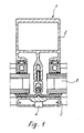
- the post or bar shown in Fig. 1 consists of a facade profile 2 and a cover profile 3, using 4 screws on the facade profile is attached. From the facade profile and the cover profile the edges are taken up by insulating glass panes 5, the ones formed by the posts and transoms Fill in the frame fields.
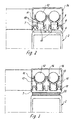
- the facade profile 2 according to FIG. 1 can accordingly the embodiments of FIGS. 2 and 3 with a device for tempering a to the Facade bordering building room equipped or be upgraded.
- an attachment profile 7 which means Screws or locking devices with the facade profile 2 can be connected.
- This attachment profile 7 has groove webs 8 and 9, limit the anchoring grooves 10, in which in the illustrated embodiments, the mounting feet are fixed by holders 11. Through the holder 11 the pipes 12 leading a heating medium to the Attachment profile 7 and thus fixed to facade profile 2. The Holders are distributed over the pipe length. You can use the anchor groove anywhere be determined.
- the holders in those shown in the drawings Exemplary embodiments have clamping legs 13, 14 on, which are adapted to the outer contour of the tube 12 and form a receptacle for the pipe.
- the clamp legs extend over an angular range that is greater than 180 °.
- a support bar 15 is provided for the tube 12 and end pieces 16 are attached to the leg ends, the triangular in the embodiment Cross-section are formed and from the clamping legs project inwards so that between the Clamp leg and the tube 12 in the area between the support bar 15 and the end piece 16 a gap 17 is provided.
- the holders are preferably made of plastic and have a mounting foot that the Embodiments of FIGS. 2,3,6,7 and 8 two spaced apart, parallel to each other extending clamping webs 18.
- the clamping bars 18 have an arrow-shaped end piece at the free end 19 on.
- This arrow-shaped end piece 19 engages behind the Groove webs 8.9 a locking edge, so that due to the Shape and material suspension of the mounting foot Clamping bars with their arrow-shaped end piece Fit non-positively on the groove webs 8.9.
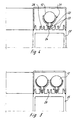
- 4 and 5 are holder 21 for receiving and Determination of the tubes 12 shown, in which the training of the mounting base deviating from the holders 11 is.
- the mounting foot of the holder 21 has a support bar 22 on the free longitudinal edges the groove webs 23 are supported. Extends from this support bar engaging in the anchoring groove Clamp bar 24.
- the facade profile 25 is equipped with groove webs 23, formed by the three anchoring grooves 26 will.
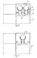
- a facade profile 27 is shown, which is equipped with a groove pattern that the corresponds to the attachment profile 7 according to FIGS. 2 and 3.
- the groove webs 8 and 9 form two parallel to each other extending anchoring grooves 10, in which accordingly 6 two heating tubes 12 or corresponding 7 a heating tube 12 can be fixed.
- a heat exchange profile 28 is clipped onto ds.
- This The heat exchange profile is radiating outwards extending ribs 29, which are a surface enlargement result and thus the heat radiation improve.
- the shown in Fig. 8 and on the heating tube 12 clipped-on heat exchange profile 28 encompasses this Heating tube 12 over an angular range that is little larger than 180 °.
- the length of the heat exchange profile 28 corresponds the distance between two adjacent holders 11.
- the heating system should preferably be inert Low temperature system can be used, which in particular has the advantage that strong temperature fluctuations do not act on the facade construction.
- the heat transfer from the heating medium to the ambient air takes place in particular via heat radiation, which intensifies according to the embodiment according to FIG. 8 can be.
- Fig. 9 shows a facade profile 29, the one in the middle area provided web 30 on both Sides anchoring grooves 31, which by groove webs 32 can be limited.
- holder 21 pipes 12 carrying a heating medium on the facade profile fixed.
- the heating pipes are opposed by a cover profile 33 encapsulates the room to be tempered.
- caps 34, 35 are provided, through which a heating medium leading pipes compared to the one to be heated Space to be covered. These caps will be made of a good heat-conducting material.
Landscapes
- Engineering & Computer Science (AREA)
- General Engineering & Computer Science (AREA)
- Chemical & Material Sciences (AREA)
- Thermal Sciences (AREA)
- Combustion & Propulsion (AREA)
- Mechanical Engineering (AREA)
- Physics & Mathematics (AREA)
- Steam Or Hot-Water Central Heating Systems (AREA)
- Building Environments (AREA)
- Buildings Adapted To Withstand Abnormal External Influences (AREA)
- Load-Bearing And Curtain Walls (AREA)
- Manufacturing And Processing Devices For Dough (AREA)
- Breeding Of Plants And Reproduction By Means Of Culturing (AREA)
- Switches With Compound Operations (AREA)
- Complex Calculations (AREA)
Claims (10)
- Façade pour la délimitation extérieure de pièces d'un bâtiment, laquelle façade est constituée d'une ossature de bâti formée par des profilés de montants et de traverses (2, 25, 27), et d'éléments de bâti (5) remplissant les panneaux du bâti, ainsi que d'un dispositif pour équilibrer la température des pièces en question, le dispositif d'équilibrage de température pouvant être ajouté par le chauffagiste ultérieurement à la construction de la façade par le constructeur d'ossatures métalliques, et ce dispositif étant prévu sur au moins une surface des profilés de montants ou de traverses tournée vers la pièce à tempérer, cette surface faisant partie des profilés de montants ou de traverses ou d'un profilé rapporté, et ladite surface étant dotée de nervures rainurées (8, 9, 23, 32) délimitant une ou plusieurs rainures d'ancrage, et ce dispositif se composant d'au moins un tuyau (12) transportant un fluide de chauffage, de supports (11, 21) recevant le ou les tuyaux et de capots (34, 35) recouvrant les supports (11, 21), les supports (11, 21) étant constitués de branches de serrage (13, 14) pour fixer en position les tuyaux (12) et d'un pied de fixation qui peut être fixé dans des moyens de crantage des profilés de façade (2, 25, 27) ou dans des moyens de crantage des profilés rapportés (7), et les capots (34, 35) présentant des moyens de crantage pour leur fixation en position sur le profilé de façade (2, 25, 27) ou sur le profilé rapporté (7), les pieds de fixation des supports (11, 21) et les moyens de crantage des capots (34, 35) pouvant être fixés en position dans les nervures rainurées.
- Façade avec un dispositif d'équilibrage de température selon la revendication 1, caractérisée en ce qu'une couche d'isolation thermique (20) est prévue entre les profilés rapportés (7) et les profilés de façade, et en ce que le profilé rapporté (7) et la couche d'isolation thermique (20) sont assemblés par vissage au profilé de façade (2).
- Façade avec un dispositif d'équilibrage de température selon la revendication 1, caractérisée en ce que les branches de serrage (13, 14) sont adaptées au contour extérieur du tuyau (12), s'étendent sur une plage angulaire qui est supérieure à 180° et s'appuient au moins à leurs extrémités libres contre le tuyau (12).
- Façade avec un dispositif d'équilibrage de température selon la revendication 3, caractérisée en ce qu'une barrette de soutien (15) pour le tuyau (12) est prévue dans la région de la base des branches de serrage, et des embouts (16) s'appliquant contre le tuyau (12) sont prévus aux extrémités des branches.
- Façade avec un dispositif d'équilibrage de température selon la revendication 1, caractérisée en ce que le pied de fixation présente une barrette d'appui (22) s'appuyant contre les bords longitudinaux libres des nervures rainurées, et une nervure de serrage (24) partant de la barrette d'appui et s'engageant dans la rainure d'ancrage.
- Façade avec un dispositif d'équilibrage de température selon la revendication 1, caractérisée en ce que le pied de fixation des supports (11) est constitué de deux nervures de serrage (18) s'étendant parallèlement à distance entre elles.
- Façade avec un dispositif d'équilibrage de température selon la revendication 6, caractérisée en ce que les nervures de serrage (18) présentent à leur extrémité libre un embout (19) en forme de flèche.
- Façade avec un dispositif d'équilibrage de température selon l'une quelconque des revendications précédentes, caractérisée en ce qu'un profilé d'échange de chaleur (28) est posé sur les tuyaux de chauffage (12).
- Façade avec un dispositif d'équilibrage de température selon la revendication 8, caractérisée en ce que le profilé d'échange de chaleur (28) est clipsé sur le tuyau de chauffage (12).
- Façade avec un dispositif d'équilibrage de température selon la revendication 8 ou 9, caractérisée en ce que le profilé d'échange de chaleur (28) présente des nervures (29) s'étendant vers l'extérieur en forme de rayons.
Applications Claiming Priority (2)
| Application Number | Priority Date | Filing Date | Title |
|---|---|---|---|
| DE4209702A DE4209702A1 (de) | 1992-03-25 | 1992-03-25 | Vorrichtung zum Temperieren von an eine Fassade grenzenden Räumen eines Gebäudes |
| DE4209702 | 1992-03-25 |
Publications (3)
| Publication Number | Publication Date |
|---|---|
| EP0562545A1 EP0562545A1 (fr) | 1993-09-29 |
| EP0562545B1 EP0562545B1 (fr) | 1996-02-28 |
| EP0562545B2 true EP0562545B2 (fr) | 1999-01-07 |
Family
ID=6454994
Family Applications (1)
| Application Number | Title | Priority Date | Filing Date |
|---|---|---|---|
| EP93104747A Expired - Lifetime EP0562545B2 (fr) | 1992-03-25 | 1993-03-23 | Dispositif pour régler la température de locaux d'un immeuble qui touchent à une façade |
Country Status (5)
| Country | Link |
|---|---|
| EP (1) | EP0562545B2 (fr) |
| AT (1) | ATE134760T1 (fr) |
| DE (2) | DE4209702A1 (fr) |
| DK (1) | DK0562545T4 (fr) |
| FI (1) | FI102781B (fr) |
Families Citing this family (6)
| Publication number | Priority date | Publication date | Assignee | Title |
|---|---|---|---|---|
| DE29612323U1 (de) * | 1996-07-16 | 1996-12-12 | Rohmann, Klaus, 44357 Dortmund | Vorrichtung zur Isolierung von Rohrleitungen |
| DE19835666C2 (de) * | 1998-08-06 | 2002-02-07 | Schneider Fensterfabrik Geb | Temperierbares Rahmenelement |
| DE19908992C2 (de) * | 1999-03-02 | 2002-06-27 | Pierre Koetz | Vorrichtung zum Temperieren von an eine Fassade angrenzenden Innenräumen |
| DE20109246U1 (de) | 2001-06-01 | 2001-12-20 | REHAU AG + Co., 95111 Rehau | Fassadensystem |
| DE202005000582U1 (de) * | 2005-01-14 | 2006-05-24 | Schüco International KG. | Profil für ein Fassadenelement mit Kabelnut und Fassadenelement |
| CN107653999B (zh) * | 2017-11-14 | 2019-07-16 | 湖南中大经纬地热开发科技有限公司 | 换热管植入式换热墙 |
Family Cites Families (2)
| Publication number | Priority date | Publication date | Assignee | Title |
|---|---|---|---|---|
| DE3507951A1 (de) * | 1985-03-06 | 1986-09-11 | Ingenieurbüro Timmer GmbH, 5657 Haan | System zum temperieren von raeumen eines gebaeudes |
| DE8660018U1 (de) * | 1986-03-01 | 1987-02-26 | Ingenieurbüro Timmer GmbH, 5657 Haan | Rahmenprofil zum Temperieren von Räumen |
-
1992
- 1992-03-25 DE DE4209702A patent/DE4209702A1/de not_active Withdrawn
-
1993
- 1993-03-23 EP EP93104747A patent/EP0562545B2/fr not_active Expired - Lifetime
- 1993-03-23 DE DE59301697T patent/DE59301697D1/de not_active Expired - Fee Related
- 1993-03-23 AT AT93104747T patent/ATE134760T1/de not_active IP Right Cessation
- 1993-03-23 DK DK93104747T patent/DK0562545T4/da active
- 1993-03-24 FI FI931310A patent/FI102781B/fi active
Also Published As
| Publication number | Publication date |
|---|---|
| ATE134760T1 (de) | 1996-03-15 |
| FI931310L (fi) | 1993-09-26 |
| EP0562545A1 (fr) | 1993-09-29 |
| FI102781B1 (fi) | 1999-02-15 |
| DK0562545T4 (da) | 1999-09-06 |
| FI931310A0 (fi) | 1993-03-24 |
| EP0562545B1 (fr) | 1996-02-28 |
| DE4209702A1 (de) | 1993-09-30 |
| DK0562545T3 (da) | 1996-04-29 |
| FI102781B (fi) | 1999-02-15 |
| DE59301697D1 (de) | 1996-04-04 |
Similar Documents
| Publication | Publication Date | Title |
|---|---|---|
| DE2945148A1 (de) | Fensterisolierung | |
| DE3040642C2 (de) | Fassadenwand | |
| EP0562545B2 (fr) | Dispositif pour régler la température de locaux d'un immeuble qui touchent à une façade | |
| EP0427880A1 (fr) | Support pour tuyaux et méthode de son fabrication | |
| DE3001949A1 (de) | Waermeisolierender rahmen mit eingesetzter scheibe o.dgl. fuellung fuer fenster, fassadenelemente o.dgl. | |
| DE8660018U1 (de) | Rahmenprofil zum Temperieren von Räumen | |
| EP0702114A1 (fr) | Disposition de fixation pour bardage à façades | |
| DE2927463A1 (de) | Fassadenwand | |
| WO1999058781A1 (fr) | Systeme de façade pour le parement d'un edifice | |
| DE3527211A1 (de) | Pfosten-riegel-konstruktion fuer metallfenster | |
| DE19835836C2 (de) | Aussteifung für Kunststoffprofile | |
| DE3632764A1 (de) | Montage-system, insbesondere fuer fassaden | |
| DE3603221A1 (de) | Aus einzelprofilen zusammengesetztes verbundprofil | |
| DE10134396C1 (de) | Bausatz zum Einsetzen eines Wandelementes in eine Wandöffnung einer doppelschaligen Ständerwand | |
| DE3048113A1 (de) | Baukonstruktionselement sowie damit hergestelltes energie- oder absorberdach bzw. energie- oder absorberfassade | |
| DE19600944C2 (de) | Fassadenkonstruktion | |
| DE3510742A1 (de) | Haltevorrichtung fuer eine glaswand bildende verglasungen | |
| DE29614812U1 (de) | Befestigungsvorrichtung | |
| DE3525876A1 (de) | Pfosten-riegel-fassadenprofilkoerper fuer fenster und fenstertueren | |
| CH673303A5 (fr) | ||
| DE2806872A1 (de) | Fassadenunterkonstruktion | |
| DE102004016215A1 (de) | Pfosten-Riegel-System mit geringer Ansichtsbreite | |
| DE8900041U1 (de) | Klotz zum Festsetzen von Glasscheiben o.dgl. in Tür- oder Fensterrahmen | |
| CH423174A (de) | Rahmen für festverglaste, belüftete oder unbelüftete Fenster, Schaufenster, Trennwände o. dgl. | |
| DE3401877A1 (de) | Haltevorrichtung fuer eine glaswand bildende verglasungen |
Legal Events
| Date | Code | Title | Description |
|---|---|---|---|
| PUAI | Public reference made under article 153(3) epc to a published international application that has entered the european phase |
Free format text: ORIGINAL CODE: 0009012 |
|
| 17P | Request for examination filed |
Effective date: 19930601 |
|
| AK | Designated contracting states |
Kind code of ref document: A1 Designated state(s): AT CH DE DK GB LI SE |
|
| 17Q | First examination report despatched |
Effective date: 19940614 |
|
| GRAA | (expected) grant |
Free format text: ORIGINAL CODE: 0009210 |
|
| AK | Designated contracting states |
Kind code of ref document: B1 Designated state(s): AT CH DE DK GB LI SE |
|
| REF | Corresponds to: |
Ref document number: 134760 Country of ref document: AT Date of ref document: 19960315 Kind code of ref document: T |
|
| REG | Reference to a national code |
Ref country code: CH Ref legal event code: NV Representative=s name: ISLER & PEDRAZZINI AG PATENTANWAELTE |
|
| REF | Corresponds to: |
Ref document number: 59301697 Country of ref document: DE Date of ref document: 19960404 |
|
| REG | Reference to a national code |
Ref country code: DK Ref legal event code: T3 |
|
| GBT | Gb: translation of ep patent filed (gb section 77(6)(a)/1977) |
Effective date: 19960328 |
|
| PLBQ | Unpublished change to opponent data |
Free format text: ORIGINAL CODE: EPIDOS OPPO |
|
| PLBI | Opposition filed |
Free format text: ORIGINAL CODE: 0009260 |
|
| PLBF | Reply of patent proprietor to notice(s) of opposition |
Free format text: ORIGINAL CODE: EPIDOS OBSO |
|
| 26 | Opposition filed |
Opponent name: INGENIEURBUERO TIMMER REICHEL GMBH Effective date: 19961127 |
|
| PLBF | Reply of patent proprietor to notice(s) of opposition |
Free format text: ORIGINAL CODE: EPIDOS OBSO |
|
| PLAW | Interlocutory decision in opposition |
Free format text: ORIGINAL CODE: EPIDOS IDOP |
|
| PLAW | Interlocutory decision in opposition |
Free format text: ORIGINAL CODE: EPIDOS IDOP |
|
| PUAH | Patent maintained in amended form |
Free format text: ORIGINAL CODE: 0009272 |
|
| 27A | Patent maintained in amended form |
Effective date: 19990107 |
|
| AK | Designated contracting states |
Kind code of ref document: B2 Designated state(s): AT CH DE DK GB LI SE |
|
| REG | Reference to a national code |
Ref country code: CH Ref legal event code: AEN Free format text: AUFRECHTERHALTUNG DES PATENTES IN GEAENDERTER FORM |
|
| GBTA | Gb: translation of amended ep patent filed (gb section 77(6)(b)/1977) | ||
| REG | Reference to a national code |
Ref country code: DK Ref legal event code: T4 |
|
| REG | Reference to a national code |
Ref country code: GB Ref legal event code: IF02 |
|
| REG | Reference to a national code |
Ref country code: CH Ref legal event code: PCAR Free format text: ISLER & PEDRAZZINI AG;POSTFACH 1772;8027 ZUERICH (CH) |
|
| PGFP | Annual fee paid to national office [announced via postgrant information from national office to epo] |
Ref country code: DK Payment date: 20090321 Year of fee payment: 17 Ref country code: AT Payment date: 20090323 Year of fee payment: 17 |
|
| PGFP | Annual fee paid to national office [announced via postgrant information from national office to epo] |
Ref country code: GB Payment date: 20090324 Year of fee payment: 17 Ref country code: CH Payment date: 20090325 Year of fee payment: 17 |
|
| PGFP | Annual fee paid to national office [announced via postgrant information from national office to epo] |
Ref country code: SE Payment date: 20090325 Year of fee payment: 17 Ref country code: DE Payment date: 20090316 Year of fee payment: 17 |
|
| REG | Reference to a national code |
Ref country code: CH Ref legal event code: PL |
|
| EUG | Se: european patent has lapsed | ||
| REG | Reference to a national code |
Ref country code: DK Ref legal event code: EBP |
|
| GBPC | Gb: european patent ceased through non-payment of renewal fee |
Effective date: 20100323 |
|
| PG25 | Lapsed in a contracting state [announced via postgrant information from national office to epo] |
Ref country code: AT Free format text: LAPSE BECAUSE OF NON-PAYMENT OF DUE FEES Effective date: 20100323 |
|
| PG25 | Lapsed in a contracting state [announced via postgrant information from national office to epo] |
Ref country code: LI Free format text: LAPSE BECAUSE OF NON-PAYMENT OF DUE FEES Effective date: 20100331 Ref country code: DE Free format text: LAPSE BECAUSE OF NON-PAYMENT OF DUE FEES Effective date: 20101001 Ref country code: CH Free format text: LAPSE BECAUSE OF NON-PAYMENT OF DUE FEES Effective date: 20100331 |
|
| PG25 | Lapsed in a contracting state [announced via postgrant information from national office to epo] |
Ref country code: GB Free format text: LAPSE BECAUSE OF NON-PAYMENT OF DUE FEES Effective date: 20100323 |
|
| PG25 | Lapsed in a contracting state [announced via postgrant information from national office to epo] |
Ref country code: DK Free format text: LAPSE BECAUSE OF NON-PAYMENT OF DUE FEES Effective date: 20100331 |
|
| PG25 | Lapsed in a contracting state [announced via postgrant information from national office to epo] |
Ref country code: SE Free format text: LAPSE BECAUSE OF NON-PAYMENT OF DUE FEES Effective date: 20100324 |