EP0562699A2 - Composant optique intégré et procédé de fabrication - Google Patents
Composant optique intégré et procédé de fabrication Download PDFInfo
- Publication number
- EP0562699A2 EP0562699A2 EP19930201496 EP93201496A EP0562699A2 EP 0562699 A2 EP0562699 A2 EP 0562699A2 EP 19930201496 EP19930201496 EP 19930201496 EP 93201496 A EP93201496 A EP 93201496A EP 0562699 A2 EP0562699 A2 EP 0562699A2
- Authority
- EP
- European Patent Office
- Prior art keywords
- circuit path
- optical
- fiber
- optical circuit
- termination
- Prior art date
- Legal status (The legal status is an assumption and is not a legal conclusion. Google has not performed a legal analysis and makes no representation as to the accuracy of the status listed.)
- Withdrawn
Links
Images
Classifications
-
- G—PHYSICS
- G02—OPTICS
- G02B—OPTICAL ELEMENTS, SYSTEMS OR APPARATUS
- G02B6/00—Light guides; Structural details of arrangements comprising light guides and other optical elements, e.g. couplings
- G02B6/10—Light guides; Structural details of arrangements comprising light guides and other optical elements, e.g. couplings of the optical waveguide type
- G02B6/12—Light guides; Structural details of arrangements comprising light guides and other optical elements, e.g. couplings of the optical waveguide type of the integrated circuit kind
-
- G—PHYSICS
- G02—OPTICS
- G02B—OPTICAL ELEMENTS, SYSTEMS OR APPARATUS
- G02B6/00—Light guides; Structural details of arrangements comprising light guides and other optical elements, e.g. couplings
- G02B6/24—Coupling light guides
- G02B6/42—Coupling light guides with opto-electronic elements
- G02B6/4201—Packages, e.g. shape, construction, internal or external details
- G02B6/4219—Mechanical fixtures for holding or positioning the elements relative to each other in the couplings; Alignment methods for the elements, e.g. measuring or observing methods especially used therefor
- G02B6/4236—Fixing or mounting methods of the aligned elements
- G02B6/4239—Adhesive bonding; Encapsulation with polymer material
-
- G—PHYSICS
- G02—OPTICS
- G02B—OPTICAL ELEMENTS, SYSTEMS OR APPARATUS
- G02B6/00—Light guides; Structural details of arrangements comprising light guides and other optical elements, e.g. couplings
- G02B6/10—Light guides; Structural details of arrangements comprising light guides and other optical elements, e.g. couplings of the optical waveguide type
- G02B6/12—Light guides; Structural details of arrangements comprising light guides and other optical elements, e.g. couplings of the optical waveguide type of the integrated circuit kind
- G02B6/122—Basic optical elements, e.g. light-guiding paths
- G02B6/125—Bends, branchings or intersections
-
- G—PHYSICS
- G02—OPTICS
- G02B—OPTICAL ELEMENTS, SYSTEMS OR APPARATUS
- G02B6/00—Light guides; Structural details of arrangements comprising light guides and other optical elements, e.g. couplings
- G02B6/24—Coupling light guides
- G02B6/26—Optical coupling means
- G02B6/30—Optical coupling means for use between fibre and thin-film device
-
- G—PHYSICS
- G02—OPTICS
- G02B—OPTICAL ELEMENTS, SYSTEMS OR APPARATUS
- G02B6/00—Light guides; Structural details of arrangements comprising light guides and other optical elements, e.g. couplings
- G02B6/24—Coupling light guides
- G02B6/36—Mechanical coupling means
- G02B6/3628—Mechanical coupling means for mounting fibres to supporting carriers
- G02B6/3648—Supporting carriers of a microbench type, i.e. with micromachined additional mechanical structures
- G02B6/3652—Supporting carriers of a microbench type, i.e. with micromachined additional mechanical structures the additional structures being prepositioning mounting areas, allowing only movement in one dimension, e.g. grooves, trenches or vias in the microbench surface, i.e. self aligning supporting carriers
-
- G—PHYSICS
- G02—OPTICS
- G02B—OPTICAL ELEMENTS, SYSTEMS OR APPARATUS
- G02B6/00—Light guides; Structural details of arrangements comprising light guides and other optical elements, e.g. couplings
- G02B6/24—Coupling light guides
- G02B6/36—Mechanical coupling means
- G02B6/3628—Mechanical coupling means for mounting fibres to supporting carriers
- G02B6/3684—Mechanical coupling means for mounting fibres to supporting carriers characterised by the manufacturing process of surface profiling of the supporting carrier
- G02B6/3696—Mechanical coupling means for mounting fibres to supporting carriers characterised by the manufacturing process of surface profiling of the supporting carrier by moulding, e.g. injection moulding, casting, embossing, stamping, stenciling, printing, or with metallic mould insert manufacturing using LIGA or MIGA techniques
-
- G—PHYSICS
- G02—OPTICS
- G02B—OPTICAL ELEMENTS, SYSTEMS OR APPARATUS
- G02B6/00—Light guides; Structural details of arrangements comprising light guides and other optical elements, e.g. couplings
- G02B6/24—Coupling light guides
- G02B6/42—Coupling light guides with opto-electronic elements
- G02B6/4201—Packages, e.g. shape, construction, internal or external details
- G02B6/4219—Mechanical fixtures for holding or positioning the elements relative to each other in the couplings; Alignment methods for the elements, e.g. measuring or observing methods especially used therefor
- G02B6/422—Active alignment, i.e. moving the elements in response to the detected degree of coupling or position of the elements
- G02B6/4225—Active alignment, i.e. moving the elements in response to the detected degree of coupling or position of the elements by a direct measurement of the degree of coupling, e.g. the amount of light power coupled to the fibre or the opto-electronic element
Definitions
- the present invention relates to an integrated optical component and its manufacture.
- French Patent FR-A-2,574,950 depicts an integrated optical component having a monolithic glass body with at least one optical circuit path formed through ion exchange on its surface.
- the optical circuit path has the same constituents as the glass body plus ions which increase its refractive index to a value greater than that of the glass body.
- the glass body is provided with, on at least one of its sides where the optical circuit path exits, a sectioned cavity molded into the glass body.
- the optical circuit path ends at the said sectioned cavity and is aligned with it in such a way that an optical device, for example, an optical fiber, is positioned in the cavity and thereby optically aligned with the optical circuit path.
- the sectioned cavity can be formed with a transverse section groove in the shape of a V.
- This integrated optical component can be manufactured by a process consisting of:
- This integrated optical component can be, for example, a connector, a coupler-divider, a single-mode coupler, a single-mode multiplexer coupler, a multimode multiplexer coupler, a coupler allowing an optical fiber to be lined up with a collimating lens, or a multimode monitor.
- One aspect of the present invention relates to an integrated optical component comprising a glass substrate with at least one ion diffused optical circuit path connected to at least one optical fiber, including at least one transverse exit groove (6,10) forming a vertical lateral surface (7) at a termination of said optical circuit path, an endface of said optical fiber abutting said termination at said vertical lateral surface, and further comprising: plateau support means (5,11) adjacent the side of said transverse exit groove opposite said optical circuit path, for supporting an uncoated portion of said optical fiber; second support means (4,12) adjacent the side of said plateau support means opposite said optical circuit path, for supporting a coated or sheathed portion of said optical fiber; and, first adhesive means for securing said optical fiber endface to said vertical lateral surface.
- Another aspect of the invention relates to a method for manufacturing such an integrated optical component which connects an optical fiber to an ion exchange optical circuit path including the steps of: forming a glass body substantially in the form of a rectangular glass block; creating at least one optical circuit path in said glass body by ion exchange; mechanically machining at least one transverse exit groove to create an termination for said optical circuit path; mechanically machining a transverse support shoulder for supporting a coated or sheathed portion of said fiber; forming plateau support means for supporting an uncoated portion of said fiber; approximately aligning an endface of said fiber with said optical circuit path termination; precisely aligning said fiber endface and said optical circuit path termination by means of a micromanipulator tool; and, securing said fiber endface to said optical circuit path termination with an adhesive means.
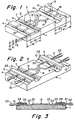
- Fig. 1 is a schematic view in perspective illustrating the body of the inventive integrated optical component in the form of a coupler.
- Fig. 2 is a schematic view of the component from Fig. 1 showing the mounting of the optical fibers.
- Fig. 3 is a vertical longitudinal cross section of the completed component.
- a monolithic glass body 1 obtained by molding is depicted, with a general rectangular block form.
- the glass body has been mechanically machined, for example, by means of abrasive grinding wheels such as 2 and 3, in such a way as to appear from left to right: a first transverse support shoulder 4 with a depth of h1, a first plateau support means 5, a first transverse exit groove 6 with a depth of h2, a first transverse interface shoulder 7 with a depth of h3 adjacent to groove 6, a horizontal central plane portion 8, a second transverse interface shoulder 9 with a depth of h3, a second transverse exit groove 10 with a depth of h2 adjacent to the shoulder 9, a second plateau support means 11, and a second transverse support shoulder 12 with a depth of h1.
- the central plane portion includes near its surface, two similar optical paths, 13 and 14, formed by ion exchange (i.e., ion diffusion), these paths including the same constituents as the glass body plus ions which raise their refractive index to a value greater than that of the glass body.
- ion exchange i.e., ion diffusion
- the optical paths are made prior to the mechanical machining of the glass body.
- the plateau support means 5 and 11 depicted in Fig. 1 include two sectioned longitudinal cavities 15 and 16 respectively, for example, at a transverse section in the form of a V, which are aligned approximately with the corresponding ends of the optical paths 13 and 14. These cavities can be achieved by molding, or by precision grinding, to list two examples.
- plateau support means 5 and 11 are formed or machined so that they are flat but have the proper height for approximate vertical alignment of the fibers. For example, their height may equal the depth of the optical circuit paths depicted in Fig. 1.
- a jig external to the glass body, but aligned with with reference to the glass body, is used to hold the optical fibers in approximate alignment prior to precise alignment by a micromanipulator tool.
- transverse support shoulder may be replaced by other suitable support means for attaching or otherwise supporting a coated or sheathed portion of said fiber.
- plateau support means 5 and 11 and the central portion 8 are on the same level and correspond to the upper surface of body 1.
- the depth h1 of the support shoulders 4 and 12 corresponds to the diameter of the coating of the optical fibers to be connected.
- the depth of h3 of interface shoulders 7 and 9 will ordinarily be slightly greater than the diameter of the stripped optical fibers to be connected.
- Depth h2 of exit grooves 6 and 10 will ordinarily be greater than h3.
- h3 can be equal to 200 ⁇ m
- h1 can be equal to 250 ⁇ m
- h2 can be equal to 400 ⁇ m.
- the transverse exit grooves allow precise alignment between an optical fiber endface and a termination of the optical circuit path by means of the micromanipulator tool (well known to one skilled in the art), after the fiber is approximately aligned with the optical circuit path to which it is to be connected.
- This initial alignment may be carried out by means of the alignment jig referred to above which contacts the fiber outside the glass body or another form of alignment device, as well as by means of the sectioned cavities formed in the plateau support means opposite the optical circuit path termination as depicted in Fig. 1.
- the depth of the transverse exit grooves must be sufficient for the micromanipulator to align precisely the optical fiber by grasping the fiber within the grooves after initial approximate alignment. Ordinarily, the depth of the transverse exit grooves will be on the order of several tenths of a millimeter (mm).
- the width of the transverse exit grooves also must be sufficient for movement of the fiber within the grooves to align the fiber precisely. For example, it can be on the order of 2 to 6 mm.
- the vertical lateral surface adjacent the optical circuit path termination should have a precise finish, (namely, an absence of scaling), as it is used as the interface for joining the optical fibers to the optical circuit path terminations.
- each of the transverse exit grooves is formed with a relatively deep part and a less deep part making up a transverse interface shoulder having a vertical surface serving as an interface for the joining of the optical fibers to the optical circuit path termination.
- the reduced depth of the vertical surface of the interface shoulder allows it to be machined more easily with the necessary high surface quality.
- the transverse interface shoulders are eliminated and only one machining step is required to create both the vertical lateral surface and the transverse exit groove, although more steps may be utilized if desired.
- the stripped portions of the fibers are positioned in the cavities 15 and 16 in such a way that their extreme ends come near the vertical lateral surface of the interface shoulder (7,9) (for example 2 to 5 ⁇ m). These fiber ends are aligned approximately with the terminations of optical paths 13 and 14, and the end of the stripped portions of fiber are spaced from the horizontal surface of interface shoulder (7,9) by a distance of several hundredths of a mm. From their side, the coated portions come to rest on the horizontal surface of support shoulder 4 or 12.
- an external jig whose position is referenced to the glass bodies (and the optical circuit paths) is attached to the fibers to provide approximate alignment.
- the fiber sheathing may be attached to a second support means at the side of the plateau support means opposite the optical circuit paths, eliminating the need for the transverse support shoulder.
- covering strips 23 for securing the fibers in cavities 15 and 16 are applied.
- the covering strips are secured with the aid of a glue 24 such as an acrylate glue, covering the portions of the fibers at the plateau support means (5 and 11) and at the first and second support shoulders (4 and 12).
- a glue 24 such as an acrylate glue
- the covering strips 23 are eliminated and glue is used as an adhesive means without the strips.
- sealing glass frit or low temperature metal alloy may be used as an adhesive means.
- the free ends of the fibers are precisely aligned with the optical circuit paths with the help of a micromaniuplator.
- the use of a micromanipulator is made possible by the presence of exit grooves which provide sufficient space for the micromanipulator to grasp the fibers.
- the ends of the fiber are then glued against the vertical lateral surface of interface shoulders 7 and 9, for example, with the help of a glue joint 25 which is of optical quality and which can be hardened by ultraviolet rays, in a known manner.
- the order of assembly is as listed above, with the glue joint 25 applied last.
- the component represented in Figs. 1 to 3 is a single-mode coupler, but it is understood that one could also use this invention in order to make a multimode coupler, a connector, a coupler-divider, a single-mode multiplexer coupler, a multimode multiplexer coupler, a multimode monitor, etc. in a way similar to that described in French Patent FR-A-2,574,950.
Landscapes
- Physics & Mathematics (AREA)
- General Physics & Mathematics (AREA)
- Optics & Photonics (AREA)
- Engineering & Computer Science (AREA)
- Microelectronics & Electronic Packaging (AREA)
- Optical Couplings Of Light Guides (AREA)
- Mechanical Coupling Of Light Guides (AREA)
- Optical Integrated Circuits (AREA)
Applications Claiming Priority (2)
| Application Number | Priority Date | Filing Date | Title |
|---|---|---|---|
| FR8703385A FR2612301B1 (fr) | 1987-03-12 | 1987-03-12 | Composant optique integre et sa fabrication |
| FR8703385 | 1987-03-12 |
Related Parent Applications (1)
| Application Number | Title | Priority Date | Filing Date |
|---|---|---|---|
| EP88302067.9 Division | 1988-03-10 |
Publications (2)
| Publication Number | Publication Date |
|---|---|
| EP0562699A2 true EP0562699A2 (fr) | 1993-09-29 |
| EP0562699A3 EP0562699A3 (en) | 1993-11-18 |
Family
ID=9348888
Family Applications (2)
| Application Number | Title | Priority Date | Filing Date |
|---|---|---|---|
| EP19930201496 Withdrawn EP0562699A3 (en) | 1987-03-12 | 1988-03-10 | Integrated optical component and method of manufacture |
| EP88302067A Ceased EP0283203A1 (fr) | 1987-03-12 | 1988-03-10 | Composant optique intégré et méthode de fabrication |
Family Applications After (1)
| Application Number | Title | Priority Date | Filing Date |
|---|---|---|---|
| EP88302067A Ceased EP0283203A1 (fr) | 1987-03-12 | 1988-03-10 | Composant optique intégré et méthode de fabrication |
Country Status (7)
| Country | Link |
|---|---|
| US (1) | US4943130A (fr) |
| EP (2) | EP0562699A3 (fr) |
| JP (1) | JPS63279206A (fr) |
| KR (1) | KR970003763B1 (fr) |
| AU (1) | AU606923B2 (fr) |
| CA (1) | CA1305343C (fr) |
| FR (1) | FR2612301B1 (fr) |
Cited By (4)
| Publication number | Priority date | Publication date | Assignee | Title |
|---|---|---|---|---|
| EP0649039A1 (fr) * | 1993-10-19 | 1995-04-19 | Matsushita Electric Industrial Co., Ltd. | Composants pour des circuits optiques et procédé de fabrication |
| GB2326951A (en) * | 1997-07-03 | 1999-01-06 | Samsung Electronics Co Ltd | Passively aligning an optical fibre with an optical waveguide |
| EP1350129A2 (fr) * | 2000-12-15 | 2003-10-08 | Intel Corporation | Alignement de fibres optiques couplees a un guide d'ondes en reseau grave |
| EP2726927A2 (fr) * | 2011-06-29 | 2014-05-07 | Tyco Electronics Corporation | Interposeur optique doté d'une surface inclinée commune |
Families Citing this family (19)
| Publication number | Priority date | Publication date | Assignee | Title |
|---|---|---|---|---|
| DE3831905A1 (de) * | 1988-09-20 | 1990-03-22 | Standard Elektrik Lorenz Ag | Optisches wellenleitermodul mit faserankopplung |
| US5046808A (en) * | 1989-12-18 | 1991-09-10 | Litton Systems, Inc. | Integrated optics chip and method of connecting optical fiber thereto |
| FR2657731A1 (fr) * | 1990-02-01 | 1991-08-02 | Corning Incorp | Amplificateur optique integre. |
| FR2661516B1 (fr) * | 1990-04-27 | 1992-06-12 | Alcatel Fibres Optiques | Composant d'optique integree et procede de fabrication. |
| US5201020A (en) * | 1990-11-08 | 1993-04-06 | Corning Incorporated | Reinforced protective tube for optical waveguide fibers |
| US5128801A (en) * | 1991-01-30 | 1992-07-07 | Corning Incorporated | Integrated optical signal amplifier |
| FR2674033B1 (fr) * | 1991-03-14 | 1993-07-23 | Corning Inc | Composant optique integre a liaison entre un guide d'onde integre et une fibre optique, fonctionnant dans un large domaine de temperature. |
| US5175781A (en) * | 1991-10-11 | 1992-12-29 | United Technologies Corporation | Attaching optical fibers to integrated optic chips |
| ES2136063T3 (es) * | 1991-11-25 | 1999-11-16 | Corning Inc | Metodo para fabricar y someter a ensayo componentes opticos integrados. |
| CA2083983A1 (fr) * | 1992-01-27 | 1993-07-28 | Kishor P. Gadkaree | Composition a faible expansion pour l'emballage des coupleurs de guide d'onde optique |
| FR2692684B1 (fr) * | 1992-06-19 | 1997-04-04 | Corning Inc | Composant optique connecte a un reseau de fibres optiques. |
| FR2693279B1 (fr) * | 1992-07-02 | 1994-09-30 | Corning Inc | Composant optique connecté à un réseau de fibres optiques et son procédé d'assemblage. |
| FR2695384B1 (fr) | 1992-09-04 | 1994-12-09 | Corning Inc | Procédé pour améliorer la fixation à l'aide d'un adhésif de fibres optiques à un substrat en verre, et composant optique intégré traité par ce procédé. |
| JPH06201936A (ja) * | 1992-12-28 | 1994-07-22 | Matsushita Electric Ind Co Ltd | 光ファイバアレイ及びその製造方法 |
| US5450513A (en) * | 1993-08-04 | 1995-09-12 | Corning Incorporated | Silane-treated optical components |
| US6490394B1 (en) * | 1996-01-16 | 2002-12-03 | Corning Incorporated | Athermal optical device |
| US7254297B1 (en) | 1996-01-16 | 2007-08-07 | Corning Incorporated | Athermal optical devices employing negative expansion substrates |
| FR2798741A1 (fr) * | 1999-09-21 | 2001-03-23 | Corning Inc | Procede de raccordement par fusion d'une fibre optique a un dispositif optique integre et structures resultantes |
| JP2012128271A (ja) * | 2010-12-16 | 2012-07-05 | Hitachi Chem Co Ltd | 光ファイバコネクタ |
Family Cites Families (8)
| Publication number | Priority date | Publication date | Assignee | Title |
|---|---|---|---|---|
| US3719462A (en) * | 1970-12-21 | 1973-03-06 | Bell Telephone Labor Inc | Light guide paths comprising densified regions in a transparent medium;and method of producing |
| US4474429A (en) * | 1982-03-04 | 1984-10-02 | Westinghouse Electric Corp. | Affixing an optical fiber to an optical device |
| FR2546311B1 (fr) * | 1983-05-17 | 1986-03-28 | France Etat | Procede et dispositif de connexion entre une fibre optique et un composant d'optique integree comportant un guide d'onde |
| JPH0664213B2 (ja) * | 1984-09-17 | 1994-08-22 | 株式会社フジクラ | 光分岐・結合器 |
| JPS62500471A (ja) * | 1984-09-28 | 1987-02-26 | アメリカン テレフオン アンド テレグラフ カムパニ− | 光導波管の横方向整合装置 |
| FR2574950B1 (fr) * | 1984-12-18 | 1987-09-25 | Corning Glass Works | Composants optiques integres en verre et leur fabrication |
| US4732449A (en) * | 1985-10-25 | 1988-03-22 | G & H Technology | Beam splitter |
| JP2505756B2 (ja) * | 1986-07-22 | 1996-06-12 | キヤノン株式会社 | 光学変調素子の駆動法 |
-
1987
- 1987-03-12 FR FR8703385A patent/FR2612301B1/fr not_active Expired - Lifetime
-
1988
- 1988-03-07 AU AU12671/88A patent/AU606923B2/en not_active Ceased
- 1988-03-08 JP JP63052775A patent/JPS63279206A/ja active Pending
- 1988-03-09 CA CA000560956A patent/CA1305343C/fr not_active Expired - Lifetime
- 1988-03-10 EP EP19930201496 patent/EP0562699A3/en not_active Withdrawn
- 1988-03-10 US US07/166,388 patent/US4943130A/en not_active Expired - Lifetime
- 1988-03-10 EP EP88302067A patent/EP0283203A1/fr not_active Ceased
- 1988-03-12 KR KR1019880002596A patent/KR970003763B1/ko not_active Expired - Lifetime
Cited By (6)
| Publication number | Priority date | Publication date | Assignee | Title |
|---|---|---|---|---|
| EP0649039A1 (fr) * | 1993-10-19 | 1995-04-19 | Matsushita Electric Industrial Co., Ltd. | Composants pour des circuits optiques et procédé de fabrication |
| US5559914A (en) * | 1993-10-19 | 1996-09-24 | Matsushita Electric Industrial Co., Ltd. | Components for optical circuits and method of manufacturing the same |
| GB2326951A (en) * | 1997-07-03 | 1999-01-06 | Samsung Electronics Co Ltd | Passively aligning an optical fibre with an optical waveguide |
| US6157759A (en) * | 1997-07-03 | 2000-12-05 | Samsung Electronics Co., Ltd. | Optical fiber passive alignment apparatus and method therefor |
| EP1350129A2 (fr) * | 2000-12-15 | 2003-10-08 | Intel Corporation | Alignement de fibres optiques couplees a un guide d'ondes en reseau grave |
| EP2726927A2 (fr) * | 2011-06-29 | 2014-05-07 | Tyco Electronics Corporation | Interposeur optique doté d'une surface inclinée commune |
Also Published As
| Publication number | Publication date |
|---|---|
| JPS63279206A (ja) | 1988-11-16 |
| FR2612301B1 (fr) | 1991-08-23 |
| US4943130A (en) | 1990-07-24 |
| KR970003763B1 (ko) | 1997-03-21 |
| CA1305343C (fr) | 1992-07-21 |
| AU1267188A (en) | 1988-09-15 |
| EP0283203A1 (fr) | 1988-09-21 |
| EP0562699A3 (en) | 1993-11-18 |
| FR2612301A1 (fr) | 1988-09-16 |
| AU606923B2 (en) | 1991-02-21 |
| KR880011606A (ko) | 1988-10-29 |
Similar Documents
| Publication | Publication Date | Title |
|---|---|---|
| US4979970A (en) | Method of manufacturing integrated optical component | |
| US4943130A (en) | Integrated optical component | |
| US5297228A (en) | Method of connecting an optical fiber to an optical waveguide | |
| US6099684A (en) | Procedure for assembling the ends of optical fibers into a sheet | |
| EP3746826B1 (fr) | Coupleurs optiques destinés au couplage évanescent de fibres revêtues de polymère à des guides d'ondes optiques à l'aide de caractéristiques d'alignement | |
| US5123068A (en) | Integrated optical component and method of manufacture | |
| US6409394B1 (en) | Optical connector | |
| EP0504882A2 (fr) | Elément de guidage d'onde optique et procédé de jonction entre cet élément et une fibre optique | |
| JP2533014Y2 (ja) | リボン状多心光ファイバの永久接続器 | |
| JP3273490B2 (ja) | 多芯マイクロキャピラリとこれを用いた光導波回路と光ファイバとの接続方法 | |
| JP3479964B2 (ja) | 光コネクタの組立方法 | |
| EP0544024B1 (fr) | Méthode pour fabriquer et tester des composants optiques intégrés | |
| JP2719353B2 (ja) | 多心光端子 | |
| EP1253452A2 (fr) | Matrice de fibres optiques | |
| JP3821971B2 (ja) | 光ファイバーアレイ | |
| EP0926522A2 (fr) | Embout intégral fusionné thermiquement et son procédé de fabrication, et procédé de fabrication pour une matrice des fibres | |
| CN115280207B (zh) | 光纤连接部件以及光纤连接部件的制造方法 | |
| EP1312955A1 (fr) | Procédé de couplage pour des fibres optiques | |
| EP1816497B1 (fr) | Connecteur optique et son procede fabrication | |
| JP3316718B2 (ja) | 光コネクタおよび光導波回路 | |
| JPH11305151A (ja) | 光スイッチの結合部及びその製造方法 | |
| JP3591967B2 (ja) | 光ガイドの接続構造 | |
| JP4172097B2 (ja) | ロッドレンズ付き光ファイバ配列部品の製造方法 | |
| JPH05134135A (ja) | 光導波路基板と光フアイバホルダとの接続方法 | |
| JP3799802B2 (ja) | 光コネクタの組立方法 |
Legal Events
| Date | Code | Title | Description |
|---|---|---|---|
| PUAI | Public reference made under article 153(3) epc to a published international application that has entered the european phase |
Free format text: ORIGINAL CODE: 0009012 |
|
| 17P | Request for examination filed |
Effective date: 19930604 |
|
| AC | Divisional application: reference to earlier application |
Ref document number: 283203 Country of ref document: EP |
|
| AK | Designated contracting states |
Kind code of ref document: A2 Designated state(s): BE DE ES FR GB IT NL SE |
|
| PUAL | Search report despatched |
Free format text: ORIGINAL CODE: 0009013 |
|
| AK | Designated contracting states |
Kind code of ref document: A3 Designated state(s): BE DE ES FR GB IT NL SE |
|
| RIN1 | Information on inventor provided before grant (corrected) |
Inventor name: THEMONT, JEAN-PIERRE Inventor name: LAROULANDIE, PIERRE JEAN Inventor name: DANNOUX, THIERRY LUC |
|
| STAA | Information on the status of an ep patent application or granted ep patent |
Free format text: STATUS: THE APPLICATION HAS BEEN WITHDRAWN |
|
| 18W | Application withdrawn |
Withdrawal date: 19950302 |