EP0562847A1 - Drainagevorrichtung für Flüssigkeiten - Google Patents
Drainagevorrichtung für Flüssigkeiten Download PDFInfo
- Publication number
- EP0562847A1 EP0562847A1 EP93302256A EP93302256A EP0562847A1 EP 0562847 A1 EP0562847 A1 EP 0562847A1 EP 93302256 A EP93302256 A EP 93302256A EP 93302256 A EP93302256 A EP 93302256A EP 0562847 A1 EP0562847 A1 EP 0562847A1
- Authority
- EP
- European Patent Office
- Prior art keywords
- water
- elongate
- supply line
- waterproof material
- flow
- Prior art date
- Legal status (The legal status is an assumption and is not a legal conclusion. Google has not performed a legal analysis and makes no representation as to the accuracy of the status listed.)
- Withdrawn
Links
- 239000012530 fluid Substances 0.000 title claims abstract description 9
- XLYOFNOQVPJJNP-UHFFFAOYSA-N water Substances O XLYOFNOQVPJJNP-UHFFFAOYSA-N 0.000 claims abstract description 27
- 239000000463 material Substances 0.000 claims abstract description 13
- 229920001971 elastomer Polymers 0.000 claims abstract description 11
- 230000004888 barrier function Effects 0.000 claims abstract description 5
- 230000003014 reinforcing effect Effects 0.000 claims description 9
- 239000002184 metal Substances 0.000 claims description 4
- 239000004033 plastic Substances 0.000 claims description 3
- 229920003023 plastic Polymers 0.000 claims description 3
- 229920001944 Plastisol Polymers 0.000 claims description 2
- 239000004999 plastisol Substances 0.000 claims description 2
- 229920001084 poly(chloroprene) Polymers 0.000 claims description 2
- 229920002994 synthetic fiber Polymers 0.000 claims 1
- 239000003643 water by type Substances 0.000 claims 1
- 230000002787 reinforcement Effects 0.000 abstract 1
- 238000010438 heat treatment Methods 0.000 description 1
- 238000012423 maintenance Methods 0.000 description 1
- 238000000034 method Methods 0.000 description 1
- 238000012986 modification Methods 0.000 description 1
- 230000004048 modification Effects 0.000 description 1
- 239000002991 molded plastic Substances 0.000 description 1
- 230000000630 rising effect Effects 0.000 description 1
- 239000002699 waste material Substances 0.000 description 1
- 239000002351 wastewater Substances 0.000 description 1
Images



Classifications
-
- F—MECHANICAL ENGINEERING; LIGHTING; HEATING; WEAPONS; BLASTING
- F24—HEATING; RANGES; VENTILATING
- F24D—DOMESTIC- OR SPACE-HEATING SYSTEMS, e.g. CENTRAL HEATING SYSTEMS; DOMESTIC HOT-WATER SUPPLY SYSTEMS; ELEMENTS OR COMPONENTS THEREFOR
- F24D19/00—Details
- F24D19/08—Arrangements for drainage, venting or aerating
- F24D19/082—Arrangements for drainage, venting or aerating for water heating systems
- F24D19/088—Draining arrangements
-
- Y—GENERAL TAGGING OF NEW TECHNOLOGICAL DEVELOPMENTS; GENERAL TAGGING OF CROSS-SECTIONAL TECHNOLOGIES SPANNING OVER SEVERAL SECTIONS OF THE IPC; TECHNICAL SUBJECTS COVERED BY FORMER USPC CROSS-REFERENCE ART COLLECTIONS [XRACs] AND DIGESTS
- Y10—TECHNICAL SUBJECTS COVERED BY FORMER USPC
- Y10T—TECHNICAL SUBJECTS COVERED BY FORMER US CLASSIFICATION
- Y10T137/00—Fluid handling
- Y10T137/5762—With leakage or drip collecting
Definitions
- This invention relates to an apparatus for fluid drainage.
- the present invention provides an apparatus for fluid drainage comprising a sheet of flexible waterproof material, having means at one end to surround a water supply line, such as a pipe, to provide a substantially water-tight seal around the supply line, and having at least one elongate reinforcing portion spaced from said means such that, when said means is positioned around the supply line, the apparatus is formed into a shape which enables catchment of a flow of water and direction of the water in a predetermined direction for collection.
- the means to surround a water supply line is in the form of a cut in the waterproof material terminating in a hole.
- the elongate reinforcing portions are of rubber or plastic material.
- the elongate reinforcing portions are formed of metal wire which can be selectively deformed to mould the apparatus to a desired shape.
- the apparatus includes two elongate reinforcing portions, the first elongate portion substantially encircling the hole in the apparatus and the second elongate portion disposed along a portion of the periphery of the apparatus.
- ridge running across the apparatus at the opposite end from said means to act as a barrier to water flow and direct the water flow in a predetermined direction.
- the two elongate portions may be raised from the waterproof material to act as a director of the water flow. In this way, the second elongate portion and the ridge may be formed in one piece.
- the flexible waterproof material may be moulded rubber.
- the flexible waterproof material may be Neoprene or PVC Plastisol.
- securing clips are provided to attach the apparatus to radiators and other bodies and to add extra rigidity to the apparatus when attached to a supply line.
- Fig 1a and 1b illustrate a first embodiment of the apparatus, wherein the apparatus is formed of a moulded rubber material in the form of a generally oval flat plate 30 with a tapered first end 31.
- the first end 31 has a slit 10 terminating in a small circular hole 3.
- the hole 3 is encircled by an elongate portion 4a in the form of a raised ridge of moulded rubber which is raised on both surfaces of the plate 30.
- the encircling ridge 4a has a break 33 at the point of the slit 10 entry within the ridge 4a.
- Extension flaps 12, 22 are provided at either side of the exit 34 of the slit 10.
- the second end 32 of the plate 30 also has an elongate portion 5a in the form of a raised ridge of moulded plastic, raised on both surfaces of the plate 30.
- the raised ridge 5a at the second end 32 is arcuate and defines a portion of the curved edge of the second end 32 of the plate 30.
- Both of the raised ridge areas 4a, 5a have an oval cross sectional.
- the raised ridge 5a at the second end 32 of the plate 30 is of a greater height from each surface of the plate 30 to that of the encircling ridge 4a.
- the raised ridge 5a at the second end 32 of the plate 30 acts as a barrier to the water flow, whereas the encircling ridge 4a primarily acts as a director of the water flow.
- the second end 32 of the plate has an extension flap 35 extending from the second end 32.
- This extension flap 35 and the two extension flaps 12, 22 either side of the slit exit 34 at the fist end 31 of the plate 30 provide an area for attachment of a clip 8 to the apparatus in order to attach the apparatus to a radiator 11 or pipe 7.
- the clips are metal sprung toothed clips of sufficient width to grip a pipe 7.
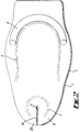
- Fig 2 illustrates an alternative form of the apparatus, wherein the apparatus for fluid drainage is formed from two identical flat pieces of rubber 1 and 2 which are glued together. A slit 10 is also cut in one end of this apparatus terminating in a small circular hole 3.
- the first wire 4 encircles the hole 3 and terminates on either side of the slit 10.
- the second wire 5 runs substantially along the periphery of the apparatus in an approximately U-shaped form.
- a cylindrical rubber element is affixed to the top surface of the apparatus at the opposite end from the slit 10 forming a ridge 6 on the surface.
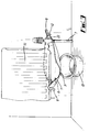
- the apparatus is attached to the bottom of a radiator 11, which is to be drained, by first pushing the slit 10 over a pipe 7 to which the radiator 11 is attached, until the pipe 7 is received by the hole 3. Two pieces of the apparatus 12 and 22 on either side of the slit 10 are then overlapped.
- the apparatus thus provides a substantially water-tight seal around the pipe 7.
- the elongate portion 4 or 4a ensures that the apparatus maintains its shape and a securing clip 8 can be attached to the apparatus if extra rigidity is considered to be necessary.
- Water escaping from the pipe 7 above the apparatus is thus directed to the centre of the apparatus and the ridge 6 acts as a barrier to water flow from the opposite end of the apparatus and helps to direct the water to the edge of the apparatus at a predetermined point 9.
- the second elongate portion 5 or 5a enables the remaining part of the apparatus to be moulded around the radiator 11 so as to direct the flow of water outward at the predetermined point 9 and into a standard container such as a basin 10.
- a second securing clip 8 can be used to attach the apparatus to the radiator 11 if necessary.
- the apparatus thus allows the controlled direction of a flow of water out of a pipe 7 to a predetermined position 9 for collection.
- the apparatus could likewise be used in other situations (illustrated in Figs 4a to 4g) such as a draincock (Fig 4a), WC cistern drain off (Fig 4b), horizontal pipe leak (Fig 4c), vertical pipe leak (Fig 4d), waste outlet (Fig 4e), rising main stopcock (Fig 4f) or water pump replacement (Fig 4g).
- a draincock Fig 4a
- WC cistern drain off Fig 4b
- horizontal pipe leak Fig 4c
- vertical pipe leak Fig 4d
- waste outlet Fig 4e
- Fig 4f rising main stopcock
- Fig 4g water pump replacement
Landscapes
- Engineering & Computer Science (AREA)
- Physics & Mathematics (AREA)
- Thermal Sciences (AREA)
- Chemical & Material Sciences (AREA)
- Combustion & Propulsion (AREA)
- Mechanical Engineering (AREA)
- General Engineering & Computer Science (AREA)
- Sewage (AREA)
- Sink And Installation For Waste Water (AREA)
- Examining Or Testing Airtightness (AREA)
Applications Claiming Priority (2)
| Application Number | Priority Date | Filing Date | Title |
|---|---|---|---|
| GB929206343A GB9206343D0 (en) | 1992-03-24 | 1992-03-24 | Apparatus for fluid drainage |
| GB9206343 | 1992-03-24 |
Publications (1)
| Publication Number | Publication Date |
|---|---|
| EP0562847A1 true EP0562847A1 (de) | 1993-09-29 |
Family
ID=10712690
Family Applications (1)
| Application Number | Title | Priority Date | Filing Date |
|---|---|---|---|
| EP93302256A Withdrawn EP0562847A1 (de) | 1992-03-24 | 1993-03-24 | Drainagevorrichtung für Flüssigkeiten |
Country Status (3)
| Country | Link |
|---|---|
| US (1) | US5365968A (de) |
| EP (1) | EP0562847A1 (de) |
| GB (2) | GB9206343D0 (de) |
Cited By (5)
| Publication number | Priority date | Publication date | Assignee | Title |
|---|---|---|---|---|
| GB2291395B (en) * | 1994-07-12 | 1998-05-06 | Ronald Joseph Patrick Gilby | Liquid collecting vessel |
| WO2000034718A1 (en) * | 1998-12-05 | 2000-06-15 | Waldco Limited | Drainage means |
| GB2449667A (en) * | 2007-05-30 | 2008-12-03 | David Povey | Fluid collecting/draining device for attachment to pipework |
| FR3043989A1 (fr) * | 2015-11-23 | 2017-05-26 | Jean Louis Ragone | Dispositif de guidage d'un liquide, un film pour un tel dispositif et kit comportant un tel dispositif |
| DE202020100201U1 (de) | 2019-01-21 | 2020-03-23 | Kiesel & Schmidt GbR (vertretungsber. Gesellsch. Marvin Kiesel, 87561 Oberstdorf, Michael Schmidt, 87561 Oberstdorf) | Flexibler Auffangbehälter |
Families Citing this family (16)
| Publication number | Priority date | Publication date | Assignee | Title |
|---|---|---|---|---|
| US5550532A (en) * | 1994-03-03 | 1996-08-27 | Shell Oil Company | Method and device for containing fuel spills and leaks |
| US5819819A (en) * | 1997-05-15 | 1998-10-13 | Stanley; Mark | Flexible oil drain apparatus |
| GB2437096B (en) * | 2006-04-11 | 2011-09-07 | John Charles Lupton | Central heating radiator drainage receptacle |
| GB2443201A (en) * | 2006-06-29 | 2008-04-30 | Jason Patrick O'connell | Apparatus for routing and collecting water from a radiator |
| GB2440008A (en) * | 2006-07-12 | 2008-01-16 | Bradley Perry | A fluid collecting/draining device |
| GB2449898A (en) * | 2007-06-07 | 2008-12-10 | Ian Mark Harris | Central heating radiator draining tool/device |
| US7954505B2 (en) * | 2007-12-03 | 2011-06-07 | Matthew Odachowski | Mobile leakage containment box including a liquid impermeable membrane |
| GB2487577B (en) * | 2011-01-28 | 2018-11-14 | Bailey Stuart | A device for collecting water as it drains from a central heating radiator |
| GB201110622D0 (en) * | 2011-06-23 | 2011-08-03 | Langston Joe | Drainage device |
| GB2503429A (en) * | 2012-06-25 | 2014-01-01 | Christopher Kirk Tanner | Pipe draining apparatus |
| US10961029B2 (en) * | 2018-11-13 | 2021-03-30 | James Darwin Klosterbuer | Micro-spill prevention trough and method of use |
| GB202011456D0 (en) * | 2020-07-23 | 2020-09-09 | Varley Andrew Edward | A radiator containment bag |
| US20230296265A1 (en) * | 2022-03-15 | 2023-09-21 | Elmer Dockery | Radiator bleeding assembly |
| GB2630012B (en) * | 2023-03-16 | 2025-04-02 | Plumbtub Ltd | Drainage device |
| US12535173B1 (en) * | 2023-03-18 | 2026-01-27 | Brendan J. Rabbett | Water containment apparatus |
| USD1029205S1 (en) * | 2023-11-21 | 2024-05-28 | Hu Zhou | Ceiling leak diverter |
Citations (2)
| Publication number | Priority date | Publication date | Assignee | Title |
|---|---|---|---|---|
| GB142768A (en) * | 1920-01-30 | 1920-05-13 | Samuel John Hally | Protective device for rubber trees |
| DE3807465A1 (de) * | 1988-03-08 | 1989-09-21 | Rolf Pfahler | Anordnung zum sammeln und abfuehren von fluessigkeiten |
Family Cites Families (12)
| Publication number | Priority date | Publication date | Assignee | Title |
|---|---|---|---|---|
| GB458714A (en) * | 1936-02-14 | 1936-12-24 | Dailley & Company Ltd | Improvements in or relating to drip mats |
| US3337418A (en) * | 1964-09-21 | 1967-08-22 | Jr Daniel S Halacy | Pneumatic solar still |
| US4313457A (en) * | 1979-11-20 | 1982-02-02 | Pittsburgh-Des Moines Corporation | Removable condensate collector for elevated water storage facilities |
| US4450855A (en) * | 1982-03-24 | 1984-05-29 | Pittsburgh-Des Moines Corporation | Removable condensate collector for elevated water storage facilities |
| US4633899A (en) * | 1984-10-15 | 1987-01-06 | Lord Phillip E | Device for providing a temporary remedy for ceiling leaks |
| US4603432A (en) * | 1985-01-22 | 1986-07-29 | Marino Thomas F | Spill containment bag and method of using the same |
| GB2214408A (en) * | 1988-01-20 | 1989-09-06 | Peter Anthony Burrell | Radiator drainage bowl |
| US4809734A (en) * | 1988-09-28 | 1989-03-07 | Cliff John O | Condensate-collecting ceiling for elevated water tower facility |
| US4819681A (en) * | 1988-10-13 | 1989-04-11 | Hodak Frank J | Apparatus and method for draining a swimming pool cover |
| AU7897891A (en) * | 1990-05-14 | 1991-12-10 | Icsc Ltd. | Land-based spill collection system |
| US5099872A (en) * | 1991-03-05 | 1992-03-31 | Tarvin Cliff A | Land-based spill collection system |
| US5172718A (en) * | 1992-04-29 | 1992-12-22 | Thornburgh Robert P | Apparatus for collecting fluids from a leaking ceiling |
-
1992
- 1992-03-24 GB GB929206343A patent/GB9206343D0/en active Pending
-
1993
- 1993-03-24 US US08/035,753 patent/US5365968A/en not_active Expired - Fee Related
- 1993-03-24 GB GB9306126A patent/GB2267749B/en not_active Expired - Fee Related
- 1993-03-24 EP EP93302256A patent/EP0562847A1/de not_active Withdrawn
Patent Citations (2)
| Publication number | Priority date | Publication date | Assignee | Title |
|---|---|---|---|---|
| GB142768A (en) * | 1920-01-30 | 1920-05-13 | Samuel John Hally | Protective device for rubber trees |
| DE3807465A1 (de) * | 1988-03-08 | 1989-09-21 | Rolf Pfahler | Anordnung zum sammeln und abfuehren von fluessigkeiten |
Cited By (7)
| Publication number | Priority date | Publication date | Assignee | Title |
|---|---|---|---|---|
| GB2291395B (en) * | 1994-07-12 | 1998-05-06 | Ronald Joseph Patrick Gilby | Liquid collecting vessel |
| WO2000034718A1 (en) * | 1998-12-05 | 2000-06-15 | Waldco Limited | Drainage means |
| GB2449667A (en) * | 2007-05-30 | 2008-12-03 | David Povey | Fluid collecting/draining device for attachment to pipework |
| GB2449667B (en) * | 2007-05-30 | 2011-11-23 | David Povey | Liquid collecting apparatus for pipework |
| FR3043989A1 (fr) * | 2015-11-23 | 2017-05-26 | Jean Louis Ragone | Dispositif de guidage d'un liquide, un film pour un tel dispositif et kit comportant un tel dispositif |
| WO2017089704A1 (fr) * | 2015-11-23 | 2017-06-01 | Ragone Jean Louis | Dispositif de guidage de matière, notamment liquide, film pour un tel dispositif et kit comportant un tel dispositif |
| DE202020100201U1 (de) | 2019-01-21 | 2020-03-23 | Kiesel & Schmidt GbR (vertretungsber. Gesellsch. Marvin Kiesel, 87561 Oberstdorf, Michael Schmidt, 87561 Oberstdorf) | Flexibler Auffangbehälter |
Also Published As
| Publication number | Publication date |
|---|---|
| US5365968A (en) | 1994-11-22 |
| GB9206343D0 (en) | 1992-05-06 |
| GB9306126D0 (en) | 1993-05-12 |
| GB2267749A (en) | 1993-12-15 |
| GB2267749B (en) | 1995-06-28 |
Similar Documents
| Publication | Publication Date | Title |
|---|---|---|
| US5365968A (en) | Apparatus for fluid drainage | |
| US4671976A (en) | Web-type stock material with upwardly projecting filamentary elements and defined periphery | |
| US4321713A (en) | Large capacity drainage receptacle | |
| US6027283A (en) | End caps for drainage system | |
| CA2535015C (en) | Faceted end cap for leaching chamber | |
| US8888465B1 (en) | Sewage handling system, cover, and controls | |
| US3980199A (en) | Gas venting for floating cover | |
| US4423527A (en) | Fabricated floor drain with combination anchoring and seepage control flange | |
| US20060228222A1 (en) | Sewage handling system, cover, and controls | |
| US7866911B2 (en) | Slotted drain | |
| US6467995B2 (en) | Self-flushing pipe | |
| EP1338706A1 (de) | Ablaufvorrichtung für Abwasser | |
| US5669187A (en) | Rodent guard | |
| US6202700B1 (en) | Self-flushing pipe | |
| EP0436093A1 (de) | Ablaufarmatur für eine Brausewanne | |
| US6085361A (en) | Sanitary toilet base band | |
| GB2146368A (en) | Gutters | |
| DE3862277D1 (de) | Reinigungsoeffnung fuer anlagen zum transportieren von fluessigkeiten. | |
| GB2353213A (en) | Shower tray | |
| DE69721174D1 (de) | Dichtungsvorrichtung für Schwimmbadauskleidung | |
| AU632384B2 (en) | Storage tank drip tray | |
| GB2443201A (en) | Apparatus for routing and collecting water from a radiator | |
| JPH0234331Y2 (de) | ||
| GB2291395A (en) | Liquid collecting tray | |
| JPH0589538U (ja) | 排水ます用掃除口 |
Legal Events
| Date | Code | Title | Description |
|---|---|---|---|
| PUAI | Public reference made under article 153(3) epc to a published international application that has entered the european phase |
Free format text: ORIGINAL CODE: 0009012 |
|
| AK | Designated contracting states |
Kind code of ref document: A1 Designated state(s): DE DK FR GB IT NL SE |
|
| STAA | Information on the status of an ep patent application or granted ep patent |
Free format text: STATUS: THE APPLICATION IS DEEMED TO BE WITHDRAWN |
|
| 18D | Application deemed to be withdrawn |
Effective date: 19940330 |