EP0562859B1 - Grille d'espacement à viroles avec perte de charge réduite - Google Patents
Grille d'espacement à viroles avec perte de charge réduite Download PDFInfo
- Publication number
- EP0562859B1 EP0562859B1 EP93302312A EP93302312A EP0562859B1 EP 0562859 B1 EP0562859 B1 EP 0562859B1 EP 93302312 A EP93302312 A EP 93302312A EP 93302312 A EP93302312 A EP 93302312A EP 0562859 B1 EP0562859 B1 EP 0562859B1
- Authority
- EP
- European Patent Office
- Prior art keywords
- ferrule
- fuel
- ferrules
- spring
- fuel rods
- Prior art date
- Legal status (The legal status is an assumption and is not a legal conclusion. Google has not performed a legal analysis and makes no representation as to the accuracy of the status listed.)
- Expired - Lifetime
Links
- 125000006850 spacer group Chemical group 0.000 title claims description 72
- 239000000446 fuel Substances 0.000 claims description 173
- XLYOFNOQVPJJNP-UHFFFAOYSA-N water Substances O XLYOFNOQVPJJNP-UHFFFAOYSA-N 0.000 claims description 37
- 238000003491 array Methods 0.000 claims description 22
- 239000011159 matrix material Substances 0.000 claims description 16
- 238000009835 boiling Methods 0.000 claims description 15
- 238000010276 construction Methods 0.000 claims description 15
- 238000000034 method Methods 0.000 claims description 9
- 239000003758 nuclear fuel Substances 0.000 claims description 8
- 239000002826 coolant Substances 0.000 claims description 7
- 230000013011 mating Effects 0.000 claims description 7
- 238000004519 manufacturing process Methods 0.000 claims description 4
- 210000004027 cell Anatomy 0.000 description 14
- 238000013461 design Methods 0.000 description 14
- 230000020169 heat generation Effects 0.000 description 6
- 238000005253 cladding Methods 0.000 description 5
- 239000002184 metal Substances 0.000 description 5
- 238000006243 chemical reaction Methods 0.000 description 4
- 239000011248 coating agent Substances 0.000 description 4
- 238000000576 coating method Methods 0.000 description 4
- 230000000694 effects Effects 0.000 description 4
- 238000003801 milling Methods 0.000 description 4
- 230000007704 transition Effects 0.000 description 4
- 229910001093 Zr alloy Inorganic materials 0.000 description 3
- 230000009286 beneficial effect Effects 0.000 description 2
- 239000012530 fluid Substances 0.000 description 2
- 239000007788 liquid Substances 0.000 description 2
- 239000000463 material Substances 0.000 description 2
- 239000007787 solid Substances 0.000 description 2
- 238000010521 absorption reaction Methods 0.000 description 1
- 229910045601 alloy Inorganic materials 0.000 description 1
- 239000000956 alloy Substances 0.000 description 1
- 238000013459 approach Methods 0.000 description 1
- 238000005452 bending Methods 0.000 description 1
- 230000015572 biosynthetic process Effects 0.000 description 1
- 230000015556 catabolic process Effects 0.000 description 1
- 210000002421 cell wall Anatomy 0.000 description 1
- 239000002131 composite material Substances 0.000 description 1
- 238000005260 corrosion Methods 0.000 description 1
- 230000007797 corrosion Effects 0.000 description 1
- 238000005520 cutting process Methods 0.000 description 1
- 238000006731 degradation reaction Methods 0.000 description 1
- 239000000203 mixture Substances 0.000 description 1
- 238000012856 packing Methods 0.000 description 1
- 239000008188 pellet Substances 0.000 description 1
- 230000002441 reversible effect Effects 0.000 description 1
- 238000012546 transfer Methods 0.000 description 1
Images



Classifications
-
- G—PHYSICS
- G21—NUCLEAR PHYSICS; NUCLEAR ENGINEERING
- G21C—NUCLEAR REACTORS
- G21C3/00—Reactor fuel elements and their assemblies; Selection of substances for use as reactor fuel elements
- G21C3/30—Assemblies of a number of fuel elements in the form of a rigid unit
- G21C3/32—Bundles of parallel pin-, rod-, or tube-shaped fuel elements
- G21C3/34—Spacer grids
- G21C3/356—Spacer grids being provided with fuel element supporting members
- G21C3/3566—Supporting members formed only of elements fixed on the strips
-
- G—PHYSICS
- G21—NUCLEAR PHYSICS; NUCLEAR ENGINEERING
- G21C—NUCLEAR REACTORS
- G21C3/00—Reactor fuel elements and their assemblies; Selection of substances for use as reactor fuel elements
- G21C3/30—Assemblies of a number of fuel elements in the form of a rigid unit
- G21C3/32—Bundles of parallel pin-, rod-, or tube-shaped fuel elements
- G21C3/34—Spacer grids
- G21C3/344—Spacer grids formed of assembled tubular elements
-
- Y—GENERAL TAGGING OF NEW TECHNOLOGICAL DEVELOPMENTS; GENERAL TAGGING OF CROSS-SECTIONAL TECHNOLOGIES SPANNING OVER SEVERAL SECTIONS OF THE IPC; TECHNICAL SUBJECTS COVERED BY FORMER USPC CROSS-REFERENCE ART COLLECTIONS [XRACs] AND DIGESTS
- Y02—TECHNOLOGIES OR APPLICATIONS FOR MITIGATION OR ADAPTATION AGAINST CLIMATE CHANGE
- Y02E—REDUCTION OF GREENHOUSE GAS [GHG] EMISSIONS, RELATED TO ENERGY GENERATION, TRANSMISSION OR DISTRIBUTION
- Y02E30/00—Energy generation of nuclear origin
- Y02E30/30—Nuclear fission reactors
Definitions
- This invention relates to fuel bundles in boiling water nuclear reactors and more particularly to a fuel rod spacer in such a fuel bundle.
- Boiling water nuclear reactors are known.
- fuel bundles contain the fuel which undergoes the nuclear reaction.
- fuel bundles include a supporting lower tie plate for holding an array of vertically upstanding fuel rods and permitting the entry of water moderator.
- a channel extends from the bottom tie plate around the fuel rods to an upper tie plate at the top of the fuel bundle. This upper tie plate permits the exit of both water and generated steam.
- fuel rod spacers Interior of the fuel bundle channel and around each of the fuel rods at selected elevations, so-called fuel rod spacers are utilized. It is the function of these fuel rod spacers to prevent the fuel rods from coming into abrading contact one with another under the fluid flow dynamic forces of steam generation as well as to maintain the designed nuclear spacing of the fuel rods for maximum nuclear efficiency. Accordingly, it is standard practice to include between 5 to 9 fuel rod spacers -- and usually 7 fuel rod spacers at usually equal vertical intervals within each fuel bundle.
- Water moderator enters the fuel bundle at the lower tie plate where the water assists the nuclear reaction in two ways.
- the reaction produces fast neutrons which must be moderated or slowed down to their thermal state where their velocity corresponds to their thermal energy due to the moderator thermal energy for continuing the reaction.
- the water coolant permits the fuel bundles to generate steam from which the power generated by the reactor can be extracted. Initially, and in the lower portion of the fuel bundle, water enters -- with no steam being present. As the moderator rises up through the fuel bundle, increasing amounts of steam are generated. These increasing amounts of steam cause the upper portion of the fuel bundle to be known as the upper two phase region -- these two phases being water and steam. Finally, the water and generated steam exit the upper tie plate of the fuel bundle.
- the fuel rod When the critical power limitation of the fuel rod is exceeded, the fuel rod no longer has a continuous coating of liquid over its surface. Instead -- and through the process known as "transition boiling" -- local interruptions of the water coating occur. As a consequence, the local temperature of the fuel rod cladding rises at the point of transition boiling. The integrity of the fuel rod is locally threatened due to possible metallurgical break down of the cladding wall at the point of transition boiling.
- ferrule spacers can have a beneficial effect on critical power. To understand this beneficial effect -- and its limitations on high density arrays of fuel rods, both the construction and the effect of such ferrule spacers should be summarized.
- each fuel rod at the elevation of the spacer is surrounded by a cylinder of metal -- usually an alloy known as Zircaloy having a relatively small cross section for the absorption of neutrons.
- Each ferrule defines a plurality of stops against which the fuel contained fuel rod can be spring biased to maintain the designed spacing of the fuel rods. Springs to effect the spring bias of the fuel rods are usually mounted within the ferrules.
- the spacers not only prevent the side-to-side abrading contact of the fuel rods but serve to maintain the fuel rods in their designed spaced apart relation for maximum nuclear and thermal efficiency.
- ferrule spacers on the critical power of such fuel rods. Specifically, and after the steam/water mixture in the upper two phase region of the fuel bundle has passed through a ferrule of a ferrule spacer, the water coating on the outside of the fuel rod tends to be restored.
- ferrule spacers can improve the critical power limitation in nuclear fuel bundles.
- ferrule spacers in high density arrays has been limited.
- the invention disclosed herein addresses the two problems described above; namely the small gap between the fuel rod and ferrule, and the increased pressure drop which occurs in high density fuel rod arrays.
- US-A-5078961 shows the construction of spacers from pairs of ferrules without significant reduction in the room needed for these.
- DE-A-3401630 shows a spacer construction with a grid made up of interengaged bent strips.
- DE-A-3413891 shows a spacer made from pairs of ferrules but without reduction in the room needed for them.
- EP-A-065613 shows a spacer made up of superimposed bent strips.
- the spacer therein disclosed is required to utilize metal strips of differing length. Such a required inventory of parts constitutes an excessive surcharge on the manufacturing process.
- the attachment of springs to the disclosed spacer is not without problems. Specifically, fastening of the springs to the cell matrix locations requires the use of loop springs carefully placed to the interlocking strips. Unfortunately, and due to the particular design utilized, the trapping of springs having reduced height between the cells is difficult.
- an improved ferrule spacer for use with high density fuel rod arrays within boiling water reactor fuel bundles comprising in combination a matrix of ferrules for surrounding fuel rods at selected elevations within said fuel bundle, said matrix of ferrules being constructed from ferrules arrayed in mating ferrule pairs; characterized in that each said ferrule is divided into upper and lower ferrule halves with at least one ferrule half having walls removed therefrom; the other ferrule half having complete walls present; each said ferrule half with walls removed is juxtaposed to a ferrule half having said wall present whereby said ferrule pair, at the junctions of the respective ferrule halves together, define a single wall between adjacent fuel rods at the point of tangency between the ferrule pair; means for defining fuel rod stops on said ferrule walls; and means for receiving and confining a spring between the ferrules of said ferrule pair for biasing fuel rods within the ferrules.
- a method of manufacturing an improved ferrule spacer for use with high density fuel rod arrays within boiling water nuclear reactor fuel bundles comprising in combination providing a matrix of ferrules for surrounding fuel rods at selected elevations within said fuel bundle, said matrix of g ferrules constructed from ferrules and 80) arrayed in mating ferrule pairs; characterized by dividing each said ferrule into upper and lower ferrule halves; removing from one said ferrule half at least one portion of a ferrule wall at a point of tangency to its adjacent ferrule of the ferrule pair; confronting said ferrule pairs with each ferrule half with a complete ferrule wall being juxtaposed to a ferrule half having said removed wall portion whereby said ferrule pair define a single wall between adjacent fuel rods at the point of tangency between the ferrules of the pair; defining fuel rod stops on said ferrule walls; and defining means defined by said ferrules for receiving
- a fuel bundle including:
- the invention provides an improved ferrule spacer for use with high density fuel rod arrays within boiling water reactor fuel bundles is disclosed.
- This spacer uses a new spring design which allows a reduced ferrule height.
- One embodiment uses the new spring design and reduced height ferrules.
- a second embodiment also uses the new spring with a reduced height ferrule, but uses a modified ferrule.
- Ferrules are constructed in mating ferrule pairs. Each ferrule is divided into upper and lower ferrule halves. One ferrule half has sides thereof with the walls removed. The other ferrule half has its in place. The ferrule pairs are confronted with each complete ferrule wall of one ferrule half being juxtaposed to a ferrule half at a missing wall.
- an aperture for receiving and confining an "H" type double loop spring is defined.
- the disclosure includes ferrules having a circular surround for the fuel rods and ferrules having an octagon sectioned surround for the fuel rods.
- Each member of the ferrule pair is symmetrical and completely interchangeable to provide for both convenient assembly and a small inventory of assembly parts.
- the spacer contains less material and has a lesser projected area presented to the flowing fluid.
- the reduction of both the projected area and the total amount of material within the spacer design here disclosed combines to give improved pressure drop performance.
- the fuel bundle B includes a lower tie plate L and upper tie plate U and a plurality of fuel rods F in a matrix extending between the respective tie plates.
- the tie plates L, U as well as the fuel rods F are surrounded by a channel C, which channel C is broken away so that a single spacer S can be seen.
- Spacer S is the subject of this invention. More particularly, a spacer S of the ferrule type is the subject of this patent application.
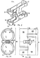
- Fig. 2 is an illustration of a particularly advantageous spring 12.
- This loop spring illustrated in Fig. 2, includes first and second vertical legs 14 and 16 containing rod contacting portions 15,17.
- One rod contacting portion of one vertical leg extends into the interior of a first ferrule of a ferrule spacer to bias a fuel rod within that ferrule.
- the other rod contacting portion of the other vertical leg extends into the interior of an adjacent second ferrule of a ferrule spacer to bias the adjacent fuel rod within that adjacent ferrule.
- This disclosed spring has a shortened construction.
- This shortened construction is provided by two horizontal loops 20,24; these horizontal loops being positioned with one loop 20 at the top of the spring and the remaining loop 24 at the bottom of the spring.
- the first and top horizontal loop is connected at its central portion to the top of each of the spring legs 14, 16.
- the second and bottom horizontal loop is connected at its central portion to the bottom of each of the spring legs 14, 16.
- top and bottom horizontal loops 20, 24 are provided with expanded loop ends 21, 22 in loop 20 and 25, 26 in loop 24. This expansion is labeled in an exemplary fashion at expanded sections 28, 30 in expanded end 25 of loop 24.
- a spring having a reduced vertical dimension with a superior deflection range results. As will hereinafter become more apparent, it is preferred to trap this spring at the expanded ends 25 between opposing ferrules for the construction of the preferred spacer of this invention.
- ferrule 42 includes a solid section 42A and an apertured section 42B having aperture 60 therein.
- ferrule 44 includes a solid section 44A and an apertured section 44B. It will be appreciated that in each of the apertured sections, four apertures 60 appear. Appropriate stops 70 are configured interior of the ferrules.
- Spring 12 (see Fig. 2) is first placed within the aperture 62 of partially confronted ferrules and thereafter the two ferrules are brought together so that the spring lies also within the aperture 64. There results the composite construction which is the essential building element of the spacer construction of this invention.
- a completed spacer S is shown using the ferrules of Figs. 3A and 3B.
- This spacer S defines intervals for water rods W1 and W2.
- a ferrule pair 40 can be seen and understood.
- first ferrule section 42 is shown confronted to second ferrule section 44.
- a centerline 46 divides each ferrule of the ferrule pair 42, 44 into respective halves.
- Ferrule 42 has halves 42A and 42B; ferrule 44 has halves 44A and 44B.
- ferrule halves 42B and 44B have four portions of their respective walls milled away. Specifically, a milling tool is utilized which has two characteristics:
- the milling tool has a diameter slightly exceeding the diameter of the adjacent ferrules. Secondly, the milling tool when cutting away the wall is centered just as the adjacent ferrule would be centered.
- ferrule half 42A fits adjacent ferrule half 44B; likewise it can be seen that ferrule half 42B fits adjacent ferrule half 44A.
- the contiguous and tangent portions of ferrule halves 42A and 44B define only one ferrule wall between adjacent fuel rods F1, F2.
- a ferrule spring 12 is trapped between ferrule aperture 62 in ferrule 42 and ferrule aperture 64 in ferrule 44. Spring 12 is captured at the respective loops interior of the confronted ferrules. As is further conventional, the respective ferrule halves 42A, 42B, 44A and 44B define respective stops 70 into which fuel rods F1 and F2 are biased by spring 12.
- a spacer S constructed of the ferrules is illustrated.
- the orientation of two water rods W1 and W2 is shown.
- bracing of the water rods at the spacer S is conventional, it is not shown.
- This invention can be applied to spacers S having octagon shaped sections. Such is shown in Figs. 5, 6A, 6B and 7.
- a Zircaloy metal sheet is shown immediately before being bent into an octagon shape.
- the cell 80 is divided into halves 80A and 80B.
- four wall portions are removed at 82, 84, 86, and 88. These removals slightly intrude upon the half 80A of the ferrule cell metal sheet.
- Conventional apertures 90A and 90B are configured for trapping spring 12.
- FIGs. 6A and 6B two respective cells 80 are assembled. Assembly is by stamping and bending using conventional manufacturing techniques. Consequently, a detailed explanation of the cell formation of the octagon shaped cell will not be offered here.
- cells 80 are shown juxtaposed with sections 80A of one cell 80 juxtaposed to section 80B of an adjacent cell 80.
- Spring 12 is trapped between the cells at apertures formed by 90A and 90B between the respective cells.
- fuel rods F1 and F2 are shown biased into conventionally constructed stops 70 by spring 12. It will be observed that only one cell wall is present between fuel rods F1 and F2.
- a completed spacer S is shown assembled.
- This spacer S defines intervals for water rods W1 and W2.
Landscapes
- Physics & Mathematics (AREA)
- Engineering & Computer Science (AREA)
- Plasma & Fusion (AREA)
- General Engineering & Computer Science (AREA)
- High Energy & Nuclear Physics (AREA)
- Monitoring And Testing Of Nuclear Reactors (AREA)
- Cooling, Air Intake And Gas Exhaust, And Fuel Tank Arrangements In Propulsion Units (AREA)
- Gasket Seals (AREA)
Claims (11)
- Grille d'espacement à viroles (S) améliorée, à utiliser avec des matrices de crayons combustibles de haute densité dans des assemblages combustibles (B) pour réacteur nucléaire à eau bouillante comprenant, en association :- une matrice de viroles destinées à entourer des crayons combustibles (F) à des hauteurs choisies dans ledit assemblage combustible (B), ladite matrice de viroles étant faite de viroles (42, 44; 80) disposées en un réseau de paires de viroles appariées (40),caractérisé en ce que chaque virole (42, 44; 80) est divisée en moitiés de virole supérieure et inférieure (42A, 44B; 42B, 44A; 80A, 80B), des parois ayant été retirées de l'une au moins des moitiés de virole (42B, 44B; 80B),les parois de l'autre moitié de virole (42A, 44A; 80A) étant présentes au complet,chaque moitié de virole (42B, 44B; 80B) dont les parois ont été retirées étant juxtaposée à une moitié de virole (42A, 44A, 80A) dont toutes les parois sont présentes, de sorte que lesdites paires de viroles (40) définissent, au niveau des jonctions entre les moitiés de viroles respectives, une paroi unique entre des crayons combustibles adjacents (F), au niveau du point de tangence entre les paires de viroles,- des moyens pour définir des dispositifs d'arrêt (70) des crayons combustibles sur lesdites parois des viroles, et- des moyens pour recevoir et retenir un ressort (12) entre les viroles (42, 44; 80) de ladite paire de viroles (40) afin de pousser les crayons combustibles à l'intérieur des viroles (42, 44; 80).
- Grille d'espacement selon la revendication 1, dans laquelle des viroles adjacentes (42, 44; 80) ont une construction identique et sont inversées l'une par rapport à l'autre.
- Grille d'espacement selon la revendication 1 ou 2, dans laquelle lesdites viroles (42, 44; 80) sont circulaires ou hexagonales.
- Grille d'espacement selon la revendication 1 ou 2, dans laquelle lesdites viroles (42, 44; 80) définissent un pourtour circulaire pour les crayons combustibles (F) ou bien un pourtour de section octogonale pour les crayons combustibles (F).
- Grille d'espacement selon l'une quelconque des précédentes revendications, dans laquelle lesdites viroles en vis-à-vis desdites paires de viroles définissent un orifice (62, 64; 90A, 90B) permettant d'enfermer entre elles un ressort (12).
- Grille d'espacement selon l'une quelconque des précédentes revendications, dans laquelle ledit ressort est un ressort (12) à profil en H, comprenant des premier et second éléments formant branches (14, 16) qui définissent des parties (15, 17) de contact avec les crayons, destinées à venir en contact avec des crayons combustibles (F) placés dans lesdites viroles (42, 44; 80) et comprenant des boucles élastiques supérieures et inférieures (20, 24) fixées aux extrémités supérieures et inférieures desdites branches de ressort (14, 16) pour fournir un fléchissement accru audit ressort (12), de sorte que ledit ressort (12) peut avoir une dimension verticale réduite entre lesdites boucles (20, 24).
- Procédé de fabrication d'une grille d'espacement à viroles améliorée, à utiliser avec des matrices de crayons combustibles de haute densité dans des assemblages combustibles (B) pour réacteur nucléaire à eau bouillante, comprenant en association :- la préparation d'une matrice de viroles destinées à entourer des crayons combustibles (F) à des hauteurs choisies dans ledit assemblage combustible (B), ladite matrice de g viroles étant faite de viroles (42, 44; 80) disposées en un réseau de paires de viroles appariées (40), caractérisé par :- la division de chaque virole en des moitiés de virole supérieure et inférieure (42A, 44B; 42B, 44A; 80A, 80B),- la suppression, dans l'une desdites moitiés de virole (42B, 44B; 80B), d'une partie au moins de la paroi au niveau du point de tangence avec la virole adjacente de la paire de viroles (40),- la mise en vis-à-vis desdites paires de viroles, chaque moitié de virole (42A, 44A; 80A) avec paroi complète étant juxtaposée à une moitié de virole (42B, 44B; 80B) dont une partie de paroi a été retirée, de sorte que ladite paire de viroles (40) définit une paroi unique entre des crayons combustibles adjacents (F) au niveau du point de tangence entre les viroles de la paire,- la formation de dispositifs (70) d'arrêt des crayons combustibles sur lesdites parois des viroles, et- la formation de moyens (62, 64; 90A, 90B) définis par lesdites viroles et servant à recevoir et contenir un ressort (12) entre les viroles de ladite paire de viroles, une première partie (15) dudit ressort (12) faisant saillie dans l'une des viroles (42; 80) de ladite paire (40) et une seconde partie (17) dudit ressort (12) faisant saillie dans la deuxième virole (44; 80) de ladite paire (40) pour pousser les crayons combustibles (F) à l'intérieur desdites viroles (42, 44; 80) jusque dans lesdits dispositifs d'arrêt (70), et- la mise en vis-à-vis desdites paires de viroles (40) pour former une matrice de viroles avec l'une desdites viroles qui entoure l'un desdits crayons combustibles à une hauteur choisie dans un assemblage combustible (B).
- Procédé selon la revendication 7, dans lequel ledit procédé comprend la mise en place d'un ressort (12) à profil en H, comprenant des premier et second éléments formant branches recouvrantes (14, 16) qui définissent des parties (15, 17) de contact avec les crayons, destinées à venir en contact avec des crayons combustibles (F) placés dans lesdites viroles (42, 44; 80) et comprenant des boucles élastiques supérieures et inférieures (20, 24) fixées aux extrémités supérieures et inférieures desdites branches de ressort (14, 16) pour fournir un fléchissement accru audit ressort (12), de sorte que ledit ressort (12) peut avoir une dimension verticale réduite entre lesdites boucles (20, 24).
- Procédé selon la revendication 7 ou 8, dans lequel ladite étape de suppression comprend la suppression des parois desdites viroles sur les quatre côtés de ladite première moitié de virole (42A, 44A; 80A).
- Assemblage combustible (B) comprenant :- une plaque inférieure d'assemblage (L) destinée à supporter une pluralité de crayons combustibles (F) verticaux et à permettre l'entrée d'eau de refroidissement autour desdits crayons combustibles (F)- une plaque supérieure d'assemblage (U) destinée à maintenir l'extrémité supérieure de l'un au moins desdits crayons combustibles (F) et à permettre la sortie hors dudit assemblage combustible (B) de l'eau de refroidissement et de la vapeur produite,- un boîtier-canal (C) qui entoure ledit assemblage combustible, comprenant ladite plaque d'assemblage inférieure (L), lesdits crayons combustibles (F) et ladite plaque d'assemblage supérieure (U), pour définir un trajet d'écoulement isolé à travers ledit assemblage combustible (B), et- au moins une grille d'espacement à viroles (S) améliorée, à utiliser avec des matrices de crayons combustibles dans des assemblages combustibles (B) pour réacteur nucléaire à eau bouillante comprenant, en association :- une matrice de viroles destinées à entourer des crayons combustibles (F) à des hauteurs choisies dans ledit assemblage combustible (B), ladite matrice de viroles étant faite de viroles (42, 44; 80) disposées en un réseau de paires de viroles appariées (40),caractérisé en ce que :- chaque virole (42, 44; 80) est divisée en moitiés de virole supérieure et inférieure (42A, 44B; 42B, 44A; 80A, 80B), l'une au moins des moitiés de virole (42B, 44B, 80B) ayant ses parois retirées,- l'autre moitié de virole (42A, 44A, 80A) ayant toutes ses parois présentes,- chaque moitié de virole (42B, 44B, 80B) dont les parois ont été retirées étant juxtaposée à une moitié de virole (42A, 44A, 80A) ayant toutes ses parois présentes, de sorte que lesdites paires de viroles définissent ensemble, au niveau des moitiés de viroles respectives, une paroi unique entre des crayons combustibles adjacents au niveau du point de tangence entre les viroles (42, 44; 80) de la paire de viroles (40),- des moyens pour définir des dispositifs d'arrêt (70) des crayons combustibles sur lesdites parois des viroles, et- des moyens (62, 64; 90A, 90B) définis par ladite paire de viroles (40), destinés à recevoir et retenir un ressort (12) servant à pousser les crayons combustibles (F) à l'intérieur des viroles de la paire de viroles.
- Assemblage combustible selon la revendication 10, dans lequel ledit assemblage combustible contient au moins un crayon d'eau (W) et ladite grille d'espacement des crayons combustibles définit un intervalle autour dudit crayon.
Applications Claiming Priority (2)
| Application Number | Priority Date | Filing Date | Title |
|---|---|---|---|
| US857153 | 1992-03-25 | ||
| US07/857,153 US5313506A (en) | 1992-03-25 | 1992-03-25 | Reduced pressure drop ferrule spacer |
Publications (2)
| Publication Number | Publication Date |
|---|---|
| EP0562859A1 EP0562859A1 (fr) | 1993-09-29 |
| EP0562859B1 true EP0562859B1 (fr) | 1997-02-12 |
Family
ID=25325318
Family Applications (1)
| Application Number | Title | Priority Date | Filing Date |
|---|---|---|---|
| EP93302312A Expired - Lifetime EP0562859B1 (fr) | 1992-03-25 | 1993-03-25 | Grille d'espacement à viroles avec perte de charge réduite |
Country Status (6)
| Country | Link |
|---|---|
| US (1) | US5313506A (fr) |
| EP (1) | EP0562859B1 (fr) |
| JP (1) | JPH0743433B2 (fr) |
| DE (1) | DE69308050T2 (fr) |
| ES (1) | ES2097446T3 (fr) |
| MX (1) | MX9301696A (fr) |
Families Citing this family (9)
| Publication number | Priority date | Publication date | Assignee | Title |
|---|---|---|---|---|
| US5488644A (en) | 1994-07-13 | 1996-01-30 | General Electric Company | Spring assemblies for adjoining nuclear fuel rod containing ferrules and a spacer formed of the spring assemblies and ferrules |
| US5610960A (en) * | 1994-08-25 | 1997-03-11 | Hitachi, Ltd. | Fuel spacer and fuel assembly |
| US5519747A (en) | 1994-10-04 | 1996-05-21 | General Electric Company | Apparatus and methods for fabricating spacers for a nuclear fuel rod bundle |
| US5546437A (en) | 1995-01-11 | 1996-08-13 | General Electric Company | Spacer for nuclear fuel rods |
| US5566217A (en) | 1995-01-30 | 1996-10-15 | General Electric Company | Reduced height spacer for nuclear fuel rods |
| US5675621A (en) * | 1995-08-17 | 1997-10-07 | General Electric Company | Reduced height flat spring spacer for nuclear fuel rods |
| KR100330355B1 (ko) * | 1999-06-04 | 2002-04-01 | 장인순 | 회전유동발생 날개를 가진 덕트형 핵연료 집합체 지지격자 |
| US7561654B2 (en) * | 2006-06-16 | 2009-07-14 | Global Nuclear Fuel - Americas, Llc | Nuclear fuel spacer assembly with debris guide |
| US10679761B2 (en) * | 2013-03-14 | 2020-06-09 | Lawerence Livermore National Security, Llc | Containers and refractory metal coating therefore for containing radioactive materials |
Family Cites Families (14)
| Publication number | Priority date | Publication date | Assignee | Title |
|---|---|---|---|---|
| BE566895A (fr) * | 1957-04-17 | |||
| GB1301584A (fr) * | 1970-04-08 | 1972-12-29 | ||
| BE794000A (fr) * | 1972-01-13 | 1973-07-12 | British Nuclear Fuels Ltd | Perfectionnements aux montages d'elements combustibles de reacteurs nucleaires |
| GB1544719A (en) * | 1977-01-12 | 1979-04-25 | British Nuclear Fuels Ltd | Cellular grids |
| ZA818675B (en) * | 1981-05-14 | 1983-08-31 | Westinghouse Electric Corp | Fuel pin support grid |
| US4508676A (en) * | 1982-07-29 | 1985-04-02 | Sorensen Jens Ole | Core stabilization by sequential injections |
| US4556531A (en) * | 1983-04-19 | 1985-12-03 | General Electric Company | Nuclear fuel assembly spacer and spring component therefor |
| DE3401630A1 (de) * | 1984-01-18 | 1985-07-18 | Kraftwerk Union AG, 4330 Mülheim | Abstandshalter fuer die brennstaebe eines kernreaktor-brennelements |
| FR2577343B1 (fr) * | 1985-02-08 | 1991-03-22 | Commissariat Energie Atomique | Dispositif d'espacement et de maintien de crayons combustibles dans un assemblage combustible |
| US4869865A (en) * | 1988-12-02 | 1989-09-26 | General Electric Company | Method of manufacturing nuclear fuel bundle spacers |
| US5078961A (en) * | 1990-12-06 | 1992-01-07 | General Electric Company | Self locating springs for ferrule spacer |
| US5173252A (en) * | 1991-05-17 | 1992-12-22 | General Electric Company | Removable springs for ferrule spacer |
| SE468571B (sv) * | 1991-06-12 | 1993-02-08 | Asea Atom Ab | Spridare foer sammanhaallande av braenslestavar i en kaernreaktors braenslepatron |
| US5130083A (en) * | 1991-08-15 | 1992-07-14 | General Electric Company | Hydride resistant spacer formed from interlocking strips |
-
1992
- 1992-03-25 US US07/857,153 patent/US5313506A/en not_active Expired - Fee Related
-
1993
- 1993-03-24 JP JP5064912A patent/JPH0743433B2/ja not_active Expired - Lifetime
- 1993-03-25 ES ES93302312T patent/ES2097446T3/es not_active Expired - Lifetime
- 1993-03-25 DE DE69308050T patent/DE69308050T2/de not_active Expired - Fee Related
- 1993-03-25 EP EP93302312A patent/EP0562859B1/fr not_active Expired - Lifetime
- 1993-03-25 MX MX9301696A patent/MX9301696A/es not_active Application Discontinuation
Also Published As
| Publication number | Publication date |
|---|---|
| DE69308050D1 (de) | 1997-03-27 |
| US5313506A (en) | 1994-05-17 |
| EP0562859A1 (fr) | 1993-09-29 |
| DE69308050T2 (de) | 1997-08-21 |
| JPH0643277A (ja) | 1994-02-18 |
| JPH0743433B2 (ja) | 1995-05-15 |
| ES2097446T3 (es) | 1997-04-01 |
| MX9301696A (es) | 1994-01-31 |
Similar Documents
| Publication | Publication Date | Title |
|---|---|---|
| US4652425A (en) | Bottom grid mounted debris trap for a fuel assembly | |
| US4957697A (en) | Nuclear fuel rod support grid with generally S-shaped spring structures | |
| US4544522A (en) | Nuclear fuel assembly spacer | |
| EP0418628B1 (fr) | Embout inférieur comportant un filtre de débris amélioré pour un assemblage de combustible nucléaire | |
| US4749544A (en) | Thin walled channel | |
| KR830001096B1 (ko) | 핵 연료 집합체의 보우잉을 감소시키는 스페이서 그리드 | |
| US6421407B1 (en) | Nuclear fuel spacer grid with dipper vanes | |
| US4357298A (en) | Nuclear fuel assembly space arrangement | |
| IT8322456A1 (it) | Distanziatore per assieme di combustibile nucleare | |
| JPH0130119B2 (fr) | ||
| EP0562859B1 (fr) | Grille d'espacement à viroles avec perte de charge réduite | |
| EP0410171B1 (fr) | Dispositif de protection de la partie inférieure de la gaine d'un crayon de combustible nucléaire | |
| EP0563694B1 (fr) | Grille d'espacement ayant une faible perte de charge pour assemblage de combustible nucléaire | |
| US5173252A (en) | Removable springs for ferrule spacer | |
| JPH0516759B2 (fr) | ||
| EP0528621B1 (fr) | Grille d'espacement résistant aux hydrures formée de lames interverrouillées pour un assemblage combustible de réacteur nucléaire à eau bouillante | |
| EP0489334B1 (fr) | Grille d'espacement à éléments tubulaires comprenant des ressorts autopositionnants | |
| US4571324A (en) | Nuclear fuel assembly spacer | |
| EP0696377B1 (fr) | Systeme de support de barres a grille d'espacement | |
| JPS637353B2 (fr) | ||
| EP1416500B1 (fr) | Grille d'espacement d'un assemblage de combustible nucléaire constituée en parois double avec des fentes laterales et étant du type à buse | |
| US5787140A (en) | Handle assembly and channel for a nuclear reactor fuel bundle assembly | |
| US5566217A (en) | Reduced height spacer for nuclear fuel rods | |
| EP0639837B1 (fr) | Dispositif d'espacement avec ressorts incorporés en zircaloy | |
| EP0319744B1 (fr) | Assemblage partiel de barreaux de combustible pour l'application dans un assemblage de combustible du type réacteur à eau bouillante |
Legal Events
| Date | Code | Title | Description |
|---|---|---|---|
| PUAI | Public reference made under article 153(3) epc to a published international application that has entered the european phase |
Free format text: ORIGINAL CODE: 0009012 |
|
| AK | Designated contracting states |
Kind code of ref document: A1 Designated state(s): CH DE ES IT LI SE |
|
| 17P | Request for examination filed |
Effective date: 19940224 |
|
| 17Q | First examination report despatched |
Effective date: 19950421 |
|
| GRAG | Despatch of communication of intention to grant |
Free format text: ORIGINAL CODE: EPIDOS AGRA |
|
| GRAH | Despatch of communication of intention to grant a patent |
Free format text: ORIGINAL CODE: EPIDOS IGRA |
|
| GRAH | Despatch of communication of intention to grant a patent |
Free format text: ORIGINAL CODE: EPIDOS IGRA |
|
| GRAA | (expected) grant |
Free format text: ORIGINAL CODE: 0009210 |
|
| AK | Designated contracting states |
Kind code of ref document: B1 Designated state(s): CH DE ES IT LI SE |
|
| PG25 | Lapsed in a contracting state [announced via postgrant information from national office to epo] |
Ref country code: LI Free format text: LAPSE BECAUSE OF FAILURE TO SUBMIT A TRANSLATION OF THE DESCRIPTION OR TO PAY THE FEE WITHIN THE PRESCRIBED TIME-LIMIT Effective date: 19970212 Ref country code: IT Free format text: LAPSE BECAUSE OF FAILURE TO SUBMIT A TRANSLATION OF THE DESCRIPTION OR TO PAY THE FEE WITHIN THE PRE;WARNING: LAPSES OF ITALIAN PATENTS WITH EFFECTIVE DATE BEFORE 2007 MAY HAVE OCCURRED AT ANY TIME BEFORE 2007. THE CORRECT EFFECTIVE DATE MAY BE DIFFERENT FROM THE ONE RECORDED.SCRIBED TIME-LIMIT Effective date: 19970212 Ref country code: CH Free format text: LAPSE BECAUSE OF FAILURE TO SUBMIT A TRANSLATION OF THE DESCRIPTION OR TO PAY THE FEE WITHIN THE PRESCRIBED TIME-LIMIT Effective date: 19970212 |
|
| REG | Reference to a national code |
Ref country code: CH Ref legal event code: EP |
|
| REF | Corresponds to: |
Ref document number: 69308050 Country of ref document: DE Date of ref document: 19970327 |
|
| REG | Reference to a national code |
Ref country code: ES Ref legal event code: FG2A Ref document number: 2097446 Country of ref document: ES Kind code of ref document: T3 |
|
| REG | Reference to a national code |
Ref country code: CH Ref legal event code: PL |
|
| PLBE | No opposition filed within time limit |
Free format text: ORIGINAL CODE: 0009261 |
|
| STAA | Information on the status of an ep patent application or granted ep patent |
Free format text: STATUS: NO OPPOSITION FILED WITHIN TIME LIMIT |
|
| 26N | No opposition filed | ||
| PGFP | Annual fee paid to national office [announced via postgrant information from national office to epo] |
Ref country code: SE Payment date: 20020305 Year of fee payment: 10 |
|
| PGFP | Annual fee paid to national office [announced via postgrant information from national office to epo] |
Ref country code: DE Payment date: 20020320 Year of fee payment: 10 |
|
| PGFP | Annual fee paid to national office [announced via postgrant information from national office to epo] |
Ref country code: ES Payment date: 20020409 Year of fee payment: 10 |
|
| PG25 | Lapsed in a contracting state [announced via postgrant information from national office to epo] |
Ref country code: SE Free format text: LAPSE BECAUSE OF NON-PAYMENT OF DUE FEES Effective date: 20030326 Ref country code: ES Free format text: LAPSE BECAUSE OF NON-PAYMENT OF DUE FEES Effective date: 20030326 |
|
| PG25 | Lapsed in a contracting state [announced via postgrant information from national office to epo] |
Ref country code: DE Free format text: LAPSE BECAUSE OF NON-PAYMENT OF DUE FEES Effective date: 20031001 |
|
| EUG | Se: european patent has lapsed | ||
| REG | Reference to a national code |
Ref country code: ES Ref legal event code: FD2A Effective date: 20030326 |