EP0563199B1 - Scie electrique circulaire portative, et pourvue d'une unite de sciage rotative et amovible - Google Patents
Scie electrique circulaire portative, et pourvue d'une unite de sciage rotative et amovible Download PDFInfo
- Publication number
- EP0563199B1 EP0563199B1 EP92901864A EP92901864A EP0563199B1 EP 0563199 B1 EP0563199 B1 EP 0563199B1 EP 92901864 A EP92901864 A EP 92901864A EP 92901864 A EP92901864 A EP 92901864A EP 0563199 B1 EP0563199 B1 EP 0563199B1
- Authority
- EP
- European Patent Office
- Prior art keywords
- saw
- motor housing
- gearing
- head
- circular
- Prior art date
- Legal status (The legal status is an assumption and is not a legal conclusion. Google has not performed a legal analysis and makes no representation as to the accuracy of the status listed.)
- Expired - Lifetime
Links
Images

Classifications
-
- B—PERFORMING OPERATIONS; TRANSPORTING
- B23—MACHINE TOOLS; METAL-WORKING NOT OTHERWISE PROVIDED FOR
- B23D—PLANING; SLOTTING; SHEARING; BROACHING; SAWING; FILING; SCRAPING; LIKE OPERATIONS FOR WORKING METAL BY REMOVING MATERIAL, NOT OTHERWISE PROVIDED FOR
- B23D45/00—Sawing machines or sawing devices with circular saw blades or with friction saw discs
- B23D45/16—Hand-held sawing devices with circular saw blades
-
- B—PERFORMING OPERATIONS; TRANSPORTING
- B23—MACHINE TOOLS; METAL-WORKING NOT OTHERWISE PROVIDED FOR
- B23D—PLANING; SLOTTING; SHEARING; BROACHING; SAWING; FILING; SCRAPING; LIKE OPERATIONS FOR WORKING METAL BY REMOVING MATERIAL, NOT OTHERWISE PROVIDED FOR
- B23D47/00—Sawing machines or sawing devices working with circular saw blades, characterised only by constructional features of particular parts
- B23D47/12—Sawing machines or sawing devices working with circular saw blades, characterised only by constructional features of particular parts of drives for circular saw blades
- B23D47/126—Angle drives
-
- B—PERFORMING OPERATIONS; TRANSPORTING
- B23—MACHINE TOOLS; METAL-WORKING NOT OTHERWISE PROVIDED FOR
- B23D—PLANING; SLOTTING; SHEARING; BROACHING; SAWING; FILING; SCRAPING; LIKE OPERATIONS FOR WORKING METAL BY REMOVING MATERIAL, NOT OTHERWISE PROVIDED FOR
- B23D57/00—Sawing machines or sawing devices not covered by one of the preceding groups B23D45/00 - B23D55/00
- B23D57/0076—Devices for converting any machine for sawing purposes
Definitions
- the present invention relates to an electrically-operated circular handsaw comprising a motor housing with an electric motor, and a saw unit detachably connected to the motor housing according to the preamble of claim 1 as for example known from SE-C-139395.
- the present invention is based on the realization that circular saws which are intended for sawing sheet metal or the like in conjunction with installation work, car repairs and the like for instance, should have an elongated main configuration with the saw blade arranged perpendicularly to the longitudinal axis of the saw.
- the saw should be divided into a saw unit and a motor unit, so as to enable these units to be replaced individually and so as to enable standard drills to be used as a drive motor.
- a compact bevelled gear is provided for power transmission between the drive motor and the saw blade, and an ergonomically and functionally adapted guide sleeve is detachably mounted on the motor housing such as to support the saw head stably and to guide the bevelled gearing connection.
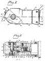
- the illustrated circular saw comprises a motor housing 11 and a saw unit 12 which are mutually connected through the intermediary of a guide sleeve 13 on the saw unit.
- the motor housing is chosen from any appropriate standard electric drill which includes conventionally an electric motor 14, a handgrip 15 and an on/off trigger 16.
- the machine has no drill chuck, but is instead connected directly to the saw unit 12.
- This connection includes the aforesaid guide sleeve 13, which has a wide collar part 17 which embraces the standard circular support neck 18 on the drill, and which has a narrower guide cylinder 19 which supports and guides a saw head 20.
- the guide sleeve 13 comprises a cylindrical body which has three mutually different diameters which decrease stepwise from the collar part 17 to an intermediate, cylindrical shoulder 14, and to the guide cylinder 19.
- a central bore 49 extends through the whole of the guide sleeve.
- Mounted in the saw head 20 is a bevelled gearing 21 comprising an input drive shaft 22 which is provided with a screw thread connection 23 and which is connected to the output drive shaft 24 of the drill.
- This screw thread connection 23 and the drive shafts 22, 24 extend through the bore 49 and are therewith encircled by and also protected by the guide sleeve 13.
- Mounted on the output shaft 25 of the bevelled gearing is a carrier device 26 which is intended to carry a circular saw blade 27.
- the input shaft 22 is journalled in the saw head 20 by means of a ball-bearing 28 and is disposed fully in line with the output shaft 24 of the drill, through the intermediary of said ball-bearing and said thread connection 23.
- a conical gear wheel 29 which functions to transmit torque to a second conical gear wheel 30 firmly mounted in the output shaft 25.
- This gearing 25 is journalled in the saw head 20 with the aid of a needle bearing 31 and a rearward ball-bearing 32, such that the shafts 25 and 22 extend perpendicularly to one another.
- the output drive shaft 25, i.e. the saw-blade carrying shaft is perpendicular to both the motor housing 11 and to the longitudinal axis of the saw unit 12.
- a cylindrical recess 33 is provided centrally in the saw head and adapted to the guide cylinder 19 on the guide sleeve 13.
- the saw head is also provided with a narrow cylindrical wall 34, which forms a junction between the saw head and the guide sleeve and which connects with the cylindrical shoulder 48 with a diameter corresponding to the diameter of the guide sleeve.
- the saw head 20 is assembled to the guide sleeve 13 with the aid of a screw device 35, consisting of one or more stop screws having conical tops and screwed through the wall of the saw head and into engagement with guide cylinder 19.
- the conical top 36 of respective stop screws is intended to engage in an annular groove 37 formed in the mantle surface of the guide cylinder.
- the groove has an angular cross-section with sloping abutment surfaces 38 intended for coaction with the conical tops 36 of respective locking screws 35.
- the guide sleeve 13 can be firmly mounted on the supporting neck 18 of the drill in some suitable, known manner, e.g. by means of locking screws 39 or by means of clamping devices which function to press the collar part 17 against the support neck. Loosening or removal of the locking screws will enable the guide sleeve 13, and therewith the whole of the saw unit 12, to be rotated around the support neck and locked in new, selected positions throughout one complete turn of the saw unit. If so desired, however, for instance for safety reasons, rotation of the saw unit can be restricted to ⁇ 90° in relation to the position shown in the drawings.
- the saw head 20 is also provided with a fixed protective cover 40 which is intended to cover at least 60% of the circumference of the saw blade and to expose only one circular segment inclined to the longitudinal axis of the saw at the forward edge of the saw.
- the saw is thus intended to be held inclined slightly forwards in relation to its longitudinal axis, when sawing on a flat support surface.
- the saw depth can be adjusted to depths of up to 25 mm, with the aid of a support plate 41 in the form of an angled plate whose one leg 42 is provided with a slot 43 which accommodates a locking screw 44.
- the other leg 45 of the plate forms a flat saw support surface, while the outer free end 46 of said other leg is bent or angled upwards towards the saw head 20, so as to form a stable support.
- the leg 42 is bent around a circular line adapted to a corresponding rounding on the saw head 20, this rounding being adapted so that the support plate 41 can rotate around the free end 46 when adjusting the saw depth, without said end moving out of abutment with the saw head.
- the saw blade 27 preferably has a diameter of about 50 mm and the tool is particularly suited for sawing steel sheet having a thickness of up to 1 mm.
- the saw is particularly suitable for sawing with the aid of saw blades of relatively small diameters, preferably between 40-60 mm and is, of course, not restricted to sawing steel sheet.
- the guide sleeve 13 When fitting the saw unit to the motor housing, the guide sleeve 13 is first loosely attached to the support neck 18 of the drill.
- the motor housing is comprised of a standard drill, as in the illustrated case, that is fitted with a drill chuck, the chuck is, of course, removed prior to fitting the guide sleeve.
- the saw head 20, together with a firmly mounted input shaft 22, is then screwed as a unit onto the shaft journal or drive shaft 24 of the drill.
- the guide sleeve and saw head are secured together to form a single unit, by tightening respective stop screws 35 so that the conical tops 36 of said screws enter the annular groove 37 and press the end of the guide sleeve against the ball-bearing 28, so as to fix the bearing in the correct position.
- the collar part 17 is then tightened firmly on the support neck, with the aid of the locking or tightening screws 39.
- the saw unit 12 is now firmly connected to the motor housing 11, but can be rotated around its own axis, as before mentioned, when the locking screws 39 are backed-off sufficient to enable the saw head to be rotated around the support neck 18 of the drill.
- the illustrated working state of the saw is normally the most appropriate, since the operator is able to grip the standard handgrip 15 on the motor housing with one hand and to grip the rearward part of the saw head and the collar 17 on the guide sleeve with the other hand.
- the collar part is preferably rounded and the saw head may be provided with an appropriate plastic covering 47 which bridges the join between the saw head and the guide sleeve.
Landscapes
- Engineering & Computer Science (AREA)
- Mechanical Engineering (AREA)
- Sawing (AREA)
Abstract
Claims (9)
- Scie électrique circulaire portative comprenant un logement du moteur (11) équipé d'un moteur électrique, et d'une unité de sciage (12), qui est reliée de façon amovible au logement du moteur, dans laquelle le logement du moteur comprend un entourage de renfort (18) et un arbre de transmission de sortie (24) pour épauler et conduire l'unité de sciage (12); et dans laquelle l'unité de sciage comprend une tête de scie (20), un engrenage biseauté (21) incorporé à ladite tête de scie, des arbres de transmission d'entrée et de sortie (22, 25) connectés à l'engrenage biseauté, et un dispositif de renfort (26) de la lame de scie circulaire (27) connecté à l'arbre de sortie, caractérisée en ce que l'unité de sciage inclut un manchon d'assemblage de guidage (13) qui peut être attaché de façon amovible à l'entourage de renfort (18) de façon à soutenir la tête de scie et à guider une liaison (23) entre l'arbre de transmission (24) du logement du moteur et l'arbre de transmission de sortie (22) connecté à l'engrenage biseauté et que le manchon d'assemblage de guidage (13) comprend un corps cylindrique ayant une large partie en collet (17) qui entoure l'entourage de renfort (18) du logement du moteur, et un cylindre de guidage plus étroit (19) pour l'engagement en rotation avec un évidement cylindrique correspondant (33) dans la tête de scie (20), et un perçage central passant à travers (49) qui entoure et protège ladite liaison (23) et lesdits arbres de transmission (22, 24).
- Une scie circulaire selon la revendication 1, caractérisée en ce que l'arbre de transmission de sortie (24) du logement du moteur et l'arbre d'entrée (22) de l'engrenage biseauté sont en ligne l'un par rapport à l'autre, tandis que l'arbre de sortie (25) dudit engrenage biseauté s'étend perpendiculairement aux arbres mentionnés en premier lieu.
- Une scie circulaire selon la revendication 1 ou 2, caractérisée en ce que l'unité de sciage (12) peut être tournée autour du entourage de renfort (18) du logement du moteur d'un angle d'au moins 180°, et peut être bloquée dans des positions choisies à l'aide des dispositifs de blocage (39).
- Une scie circulaire selon l'une quelconque des revendications précédentes, caractérisée en ce que la tête de scie est guidée et peut être bloquée dans le cylindre guide (19) à l'aide d'une rainure annulaire (37) disposée à l'intérieur et des dispositifs vissés (35) dans la tête de scie (20).
- Une scie circulaire selon la revendication 4, caractérisée en ce que le dispositif à vis a une pointe conique (36); et en ce que la rainure dans le cylindre de guidage a une surface de contact qui est inclinée d'une manière correspondant à l'inclinaison de la pointe conique (36) et qui co-agit avec ladite pointe conique, de manière à presser la tête de scie (20) et le manchon d'assemblage de guidage (13) ensemble en bloquant l'extrémité dudit manchon.
- Une scie circulaire selon l'une quelconque des revendications précédentes, caractérisée en ce que le logement du moteur a la forme d'une perceuse à main électrique avec le mandrin de la perceuse séparé de celle-ci (24), et en ce que la liaison entre ledit arbre de transmission de sortie et l'arbre de transmission (22) de l'engrenage biseauté a la forme d'une liaison par vis (23) qui s'adapte au pas de vis du mandrin.
- Une scie circulaire selon l'une quelconque des revendications précédentes, caractérisée en ce que l'engrenage biseauté (21) est un engrenage conique qui inclut un premier engrenage conique (29) monté sur cette extrémité de l'arbre d'entrée, situé dans l'engrenage, et un second engrenage conique (30) qui est monté sur l'arbre de sortie (25) dudit engrenage.
- Une scie circulaire selon l'une quelconque des revendications précédentes, caractérisée en ce que l'unité de sciage est destinée à scier avec des lames de scie (27) d'un diamètre relativement petit, de préférence des diamètres entre 40-75 mm; et en ce que la tête de scie (20) inclut un capot protecteur fixe (40) qui est destinée à couvrir en protégeant au moins 60% de la périphérie de ladite lame de scie.
- Une scie circulaire selon l'une quelconque des revendications précédentes, caractérisée en ce qu'on a monté sur la tête de scie (20) un plateau de renfort ajustable (41) pour déterminer l'épaisseur de la scie; et en ce que le plateau de renfort (41) comprend une patte de fixation coudée (42) comportant une rainure (43) qui reçoit une vis de blocage (44), et une seconde patte (45) qui est destinée à épauler d'une manière qui soutient la pièce qui vient d'être sciée, l'extrémité libre (46) de ladite patte de renfort étant repliée vers le haut de façon à venir en contact avec la tête de scie (20).
Applications Claiming Priority (3)
| Application Number | Priority Date | Filing Date | Title |
|---|---|---|---|
| SE9004053 | 1990-12-19 | ||
| SE9004053A SE467344B (sv) | 1990-12-19 | 1990-12-19 | Handhaallen eldriven cirkelsaag med en vridbar och loestagbar saagenhet |
| PCT/SE1991/000878 WO1992011112A1 (fr) | 1990-12-19 | 1991-12-18 | Scie electrique circulaire portative, et pourvue d'une unite de sciage rotative et amovible |
Publications (2)
| Publication Number | Publication Date |
|---|---|
| EP0563199A1 EP0563199A1 (fr) | 1993-10-06 |
| EP0563199B1 true EP0563199B1 (fr) | 1995-09-20 |
Family
ID=20381238
Family Applications (1)
| Application Number | Title | Priority Date | Filing Date |
|---|---|---|---|
| EP92901864A Expired - Lifetime EP0563199B1 (fr) | 1990-12-19 | 1991-12-18 | Scie electrique circulaire portative, et pourvue d'une unite de sciage rotative et amovible |
Country Status (5)
| Country | Link |
|---|---|
| EP (1) | EP0563199B1 (fr) |
| AU (1) | AU9110391A (fr) |
| DE (1) | DE69113282T2 (fr) |
| SE (1) | SE467344B (fr) |
| WO (1) | WO1992011112A1 (fr) |
Cited By (1)
| Publication number | Priority date | Publication date | Assignee | Title |
|---|---|---|---|---|
| CN111054976A (zh) * | 2019-12-25 | 2020-04-24 | 傲基科技股份有限公司 | 多功能斜切锯 |
Families Citing this family (4)
| Publication number | Priority date | Publication date | Assignee | Title |
|---|---|---|---|---|
| US5697158A (en) * | 1995-12-21 | 1997-12-16 | Minnesota Mining And Manufacturing Company | Orthopedic surgical device having a rotatable portion and lock |
| US20030113947A1 (en) | 2001-12-19 | 2003-06-19 | Vandentop Gilroy J. | Electrical/optical integration scheme using direct copper bonding |
| GB2394693A (en) * | 2002-10-29 | 2004-05-05 | James Newman | A circular blade attachment for a hand drill |
| CA2886733C (fr) * | 2014-04-01 | 2023-02-14 | Robert Bosch Tool Corporation | Dispositif de scie dote d'un mecanisme d'entrainement de couple conique |
Family Cites Families (3)
| Publication number | Priority date | Publication date | Assignee | Title |
|---|---|---|---|---|
| SE139395C1 (fr) * | ||||
| SE360815B (fr) * | 1968-01-18 | 1973-10-08 | Husqvarna Ab | |
| SE385806B (sv) * | 1973-07-09 | 1976-07-26 | Partner Ab | Portabelt kapredskap |
-
1990
- 1990-12-19 SE SE9004053A patent/SE467344B/sv not_active IP Right Cessation
-
1991
- 1991-12-18 AU AU91103/91A patent/AU9110391A/en not_active Abandoned
- 1991-12-18 WO PCT/SE1991/000878 patent/WO1992011112A1/fr not_active Ceased
- 1991-12-18 EP EP92901864A patent/EP0563199B1/fr not_active Expired - Lifetime
- 1991-12-18 DE DE69113282T patent/DE69113282T2/de not_active Expired - Fee Related
Cited By (1)
| Publication number | Priority date | Publication date | Assignee | Title |
|---|---|---|---|---|
| CN111054976A (zh) * | 2019-12-25 | 2020-04-24 | 傲基科技股份有限公司 | 多功能斜切锯 |
Also Published As
| Publication number | Publication date |
|---|---|
| DE69113282D1 (de) | 1995-10-26 |
| AU9110391A (en) | 1992-07-22 |
| WO1992011112A1 (fr) | 1992-07-09 |
| EP0563199A1 (fr) | 1993-10-06 |
| SE9004053D0 (sv) | 1990-12-19 |
| DE69113282T2 (de) | 1996-02-22 |
| SE467344B (sv) | 1992-07-06 |
Similar Documents
| Publication | Publication Date | Title |
|---|---|---|
| US6146067A (en) | Pipe beveling attachment for a power tool | |
| US7628683B2 (en) | Handheld power tool with a guard hood | |
| US6138364A (en) | Variable angle reciprocating tool | |
| US6442848B1 (en) | Coping saw | |
| US9248562B2 (en) | Accessory attachment system for an oscillating power tool | |
| US7458882B2 (en) | Adjustable handheld tool | |
| US4236356A (en) | Cutting saw and concrete groover | |
| ATE130238T1 (de) | Spindel zum festspannen von kreissägeblättern. | |
| US20180281086A1 (en) | Handheld, hand-guided cutting-off machine | |
| US7752699B1 (en) | Tubing preparation machine | |
| CN101468403A (zh) | 电动刳刨工具 | |
| US4615117A (en) | Fits-all power bar | |
| US7131898B2 (en) | Adjustable surface positioning guide for a rotary hand-held tool | |
| JPH04226870A (ja) | 手持式動力ねじ回し装置 | |
| EP0563199B1 (fr) | Scie electrique circulaire portative, et pourvue d'une unite de sciage rotative et amovible | |
| CA2231654A1 (fr) | Appareil pour l'usinage des extremites de tubes | |
| US6574874B2 (en) | Machine tool for cutting work | |
| EP0788421B1 (fr) | Outil a moteur a commande manuelle | |
| US3762452A (en) | Attachment for a hand tool | |
| US20020088326A1 (en) | Air tool for sectioning a length of tubing | |
| US5870827A (en) | Sawblade and stabilizing handle attachments for a power drill | |
| US4243083A (en) | Boring attachment for radial arm saws | |
| US20250345866A1 (en) | Multi-function beveling and weld bead removal tool | |
| US3747650A (en) | Auxiliary tool adapter for electric hand saws | |
| KR200186152Y1 (ko) | 드릴전동톱 |
Legal Events
| Date | Code | Title | Description |
|---|---|---|---|
| PUAI | Public reference made under article 153(3) epc to a published international application that has entered the european phase |
Free format text: ORIGINAL CODE: 0009012 |
|
| 17P | Request for examination filed |
Effective date: 19930607 |
|
| AK | Designated contracting states |
Kind code of ref document: A1 Designated state(s): DE FR GB IT |
|
| 17Q | First examination report despatched |
Effective date: 19940627 |
|
| RAP1 | Party data changed (applicant data changed or rights of an application transferred) |
Owner name: POWERTOOLS SWEDEN AKTIEBOLAG |
|
| GRAA | (expected) grant |
Free format text: ORIGINAL CODE: 0009210 |
|
| AK | Designated contracting states |
Kind code of ref document: B1 Designated state(s): DE FR GB IT |
|
| PG25 | Lapsed in a contracting state [announced via postgrant information from national office to epo] |
Ref country code: IT Free format text: LAPSE BECAUSE OF FAILURE TO SUBMIT A TRANSLATION OF THE DESCRIPTION OR TO PAY THE FEE WITHIN THE PRE;WARNING: LAPSES OF ITALIAN PATENTS WITH EFFECTIVE DATE BEFORE 2007 MAY HAVE OCCURRED AT ANY TIME BEFORE 2007. THE CORRECT EFFECTIVE DATE MAY BE DIFFERENT FROM THE ONE RECORDED.SCRIBED TIME-LIMIT Effective date: 19950920 Ref country code: FR Effective date: 19950920 |
|
| REF | Corresponds to: |
Ref document number: 69113282 Country of ref document: DE Date of ref document: 19951026 |
|
| EN | Fr: translation not filed | ||
| PLBE | No opposition filed within time limit |
Free format text: ORIGINAL CODE: 0009261 |
|
| STAA | Information on the status of an ep patent application or granted ep patent |
Free format text: STATUS: NO OPPOSITION FILED WITHIN TIME LIMIT |
|
| 26N | No opposition filed | ||
| PGFP | Annual fee paid to national office [announced via postgrant information from national office to epo] |
Ref country code: GB Payment date: 20011207 Year of fee payment: 11 |
|
| PGFP | Annual fee paid to national office [announced via postgrant information from national office to epo] |
Ref country code: DE Payment date: 20011220 Year of fee payment: 11 |
|
| REG | Reference to a national code |
Ref country code: GB Ref legal event code: IF02 |
|
| PG25 | Lapsed in a contracting state [announced via postgrant information from national office to epo] |
Ref country code: GB Free format text: LAPSE BECAUSE OF NON-PAYMENT OF DUE FEES Effective date: 20021218 |
|
| PG25 | Lapsed in a contracting state [announced via postgrant information from national office to epo] |
Ref country code: DE Free format text: LAPSE BECAUSE OF NON-PAYMENT OF DUE FEES Effective date: 20030701 |
|
| GBPC | Gb: european patent ceased through non-payment of renewal fee |
Effective date: 20021218 |