EP0563658B1 - Caméra pliable - Google Patents
Caméra pliable Download PDFInfo
- Publication number
- EP0563658B1 EP0563658B1 EP93104104A EP93104104A EP0563658B1 EP 0563658 B1 EP0563658 B1 EP 0563658B1 EP 93104104 A EP93104104 A EP 93104104A EP 93104104 A EP93104104 A EP 93104104A EP 0563658 B1 EP0563658 B1 EP 0563658B1
- Authority
- EP
- European Patent Office
- Prior art keywords
- mount
- camera
- flash unit
- lens
- camming
- Prior art date
- Legal status (The legal status is an assumption and is not a legal conclusion. Google has not performed a legal analysis and makes no representation as to the accuracy of the status listed.)
- Expired - Lifetime
Links
Images

Classifications
-
- G—PHYSICS
- G03—PHOTOGRAPHY; CINEMATOGRAPHY; ANALOGOUS TECHNIQUES USING WAVES OTHER THAN OPTICAL WAVES; ELECTROGRAPHY; HOLOGRAPHY
- G03B—APPARATUS OR ARRANGEMENTS FOR TAKING PHOTOGRAPHS OR FOR PROJECTING OR VIEWING THEM; APPARATUS OR ARRANGEMENTS EMPLOYING ANALOGOUS TECHNIQUES USING WAVES OTHER THAN OPTICAL WAVES; ACCESSORIES THEREFOR
- G03B17/00—Details of cameras or camera bodies; Accessories therefor
- G03B17/02—Bodies
- G03B17/04—Bodies collapsible, foldable or extensible, e.g. book type
-
- G—PHYSICS
- G03—PHOTOGRAPHY; CINEMATOGRAPHY; ANALOGOUS TECHNIQUES USING WAVES OTHER THAN OPTICAL WAVES; ELECTROGRAPHY; HOLOGRAPHY
- G03B—APPARATUS OR ARRANGEMENTS FOR TAKING PHOTOGRAPHS OR FOR PROJECTING OR VIEWING THEM; APPARATUS OR ARRANGEMENTS EMPLOYING ANALOGOUS TECHNIQUES USING WAVES OTHER THAN OPTICAL WAVES; ACCESSORIES THEREFOR
- G03B15/00—Special procedures for taking photographs; Apparatus therefor
- G03B15/02—Illuminating scene
- G03B15/03—Combinations of cameras with lighting apparatus; Flash units
- G03B15/05—Combinations of cameras with electronic flash apparatus; Electronic flash units
-
- G—PHYSICS
- G03—PHOTOGRAPHY; CINEMATOGRAPHY; ANALOGOUS TECHNIQUES USING WAVES OTHER THAN OPTICAL WAVES; ELECTROGRAPHY; HOLOGRAPHY
- G03B—APPARATUS OR ARRANGEMENTS FOR TAKING PHOTOGRAPHS OR FOR PROJECTING OR VIEWING THEM; APPARATUS OR ARRANGEMENTS EMPLOYING ANALOGOUS TECHNIQUES USING WAVES OTHER THAN OPTICAL WAVES; ACCESSORIES THEREFOR
- G03B2215/00—Special procedures for taking photographs; Apparatus therefor
- G03B2215/05—Combinations of cameras with electronic flash units
- G03B2215/0503—Built-in units
- G03B2215/0507—Pop-up mechanisms
Definitions
- This invention relates to a camera that can be folded into a compact, closed, storage configuration when not in use, but which can be unfolded into an open, ready-standby position when photographs are to be taken. More particularly, this invention relates to a camera provided with a flash unit and housing-enclosed, lens/shutter assembly, both of which can be retracted within the camera encasement when the camera is configured in an inactive mode, but which can be deployed in an active mode when photographs are to be taken.
- this invention relates to a fixed-focus camera with an integral, built-in flash unit, manually movable between a camera-storage position, and a camera-operating position, movement of the flash unit causing corresponding movement in a mount holding a viewfinder and baffle cone-lens/shutter assembly between a storage position, and an operating position.
- Still additional cameras have been proposed, for example, that shown in U.S. Patent 4,452,519, which include an integral flash unit and other camera components essential to the picture-taking process that are automatically deployed when the camera is unfolded for use, but which fold into a protected, enclosed position when the camera is disposed in its storage mode.
- a common drawback of these cameras stems from the fact that they tend to be relatively complicated, involving extensive operating structure and numerous component parts. As a consequence, such cameras are prone to operational difficulties and are oftentimes expensive.
- cameras of the type described are often more bulky, and therefore, inconvenient to carry about and to hold during the photographic process.
- a mount carrying a lens/shutter assembly and a front component of a viewfinder is movable between a storage position for protecting the front lens/shutter assembly and an active position for presenting said lens/shutter assembly and said front component for photographic use.
- the said mount In response to the movement of said flash unit into the use position the said mount will be biased from the storage position into the active position.
- uncomplicated biasing means as defined in claim 1 for biasing the lens/shutter mount to move in response to the movement of the flash unit into the wanted position.
- Cameras of the type with which the invention is concerned are those known as fixed-focus cameras, typically having the capability of focusing subjects located from about 1,22 m (4 feet) to infinity, relative to the camera lens.
- the cameras of the invention are designed to accommodate a built-in flash unit in a storage recess provided within the body of the camera, and are not only compact, but rugged and easy to hold, form following function in this regard. Although the cameras are manually moved to and from their storage position, they could if desired be provided with motorized means for accomplishing the transition between their active and inactive positions.
- FIG. 1 is an isometric view of the camera, generally 10, folded into its closed or storage position.
- the lens/shutter housing enclosing the lens/shutter assembly has been withdrawn into the camera housing or encasement 18 of the camera protecting it from accidental blows and other inadvertent damage.
- the act of pivoting the flash housing 16 from an erect, use position, downward into its horizontal, stored position is the action which causes the withdrawal of the lens/shutter housing 12 and its contained lens/shutter assembly 13.
- the camera contemplated by the invention is designed to be compact for easy carrying, therefore, although cameras having different dimensions could make use of the folding concept of the invention, commonly, the length of the camera will be from about 100-125 mm, while its width will conveniently be from about 25 to 40 mm. Such a camera will often have a height of from about 55 to 75 mm.
- FIG. 2 is an isometric view of the camera of the invention, generally 10, in an open, or use position.
- the flash housing 16 has been rotated clockwise (when viewed from the left part of the Figure) from its horizontal position of storage in recess 15 of the camera encasement 18 into a vertical, use position.
- such action has resulted in propelling the front viewfinder lens component or element 14 into the recess 15 (element 14 can be composed of one or more lens pieces), previously occupied by the flash unit, and has extended the lens/shutter assembly housing 12, and its enclosed lens/shutter assembly 13 outwardly from the front of the camera.
- the camera is in a condition for taking photographs.
- a vertical distance of from about 15 to 20 mm is typically provided, but more preferably, from about 30 to 40 mm.
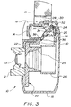
- FIG. 3 is a cross-section of the camera of the invention, generally 10, in its open, use position.
- a flash unit 16 is provided, pivotal about flash unit pivot pin 28.
- Attached to the flash unit 16 is a pivot arm 29, at the end of which is disposed a flash unit cam follower pin 34.
- An actuating lever 20, pivotal about actuating lever pivot pin 30, is also provided, the lever having a lever bar 36, better seen in FIG. 5, located on the end thereof.
- the pivot pins 28 and 30, respectively, of flash unit 16 and actuating lever 20 are mounted on the camera frame 26, also as better seen in FIG. 5.
- the flash unit cam follower pin 34 is located in lever cam slot 32 of the actuating lever 20, the pin and lever together constituting biasing means for mount 22.
- the travel of the follower pin has caused the actuating lever 20 to pivot clockwise toward the front of the camera.
- Such pivoting causes the lever bar 36 to move from lever bar storage notch 40, where it is shown in FIG. 4, to a lever bar locking notch 38.
- the lever bar 36 has been urged or biased against mount 22, the latter being interconnected, for example, with the front viewfinder component 14, light baffle cone 25, and the housing 12 which encloses the lens/shutter assembly 13.
- Movement of the mount 22 causes the front viewfinder element 14 to move forward in the camera into the recess 15, previously occupied by flash unit 16 in its storage position, and moves the housing 12 and its contained lens/shutter assembly 13 outwardly from the front of the camera. Portions of the frame 26 of the camera and the camera encasement 18 are also illustrated in the Figure.
- the lens In moving forward to the position shown, the lens will commonly move by a distance as measured between the lens and the plane of the film in the camera of from about 7,62 mm to 25,4 mm (0.3 to 1 inch), about 11,43 mm (0.45 inch) being normal, this distance corresponding to the travel of viewfinder element 14.
- the flash unit cam follower pin 34 travels downwardly along lever cam slot 32 in actuating lever 20 until such movement causes the actuating lever 20 to move into the stable, angled position illustrated in the Figure with the lever bar 36 being firmly positioned in lever bar locking notch 38. In this position, the components interconnected with mount 22 are stably retained in the position shown in the Figure.
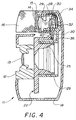
- FIG. 4 is a cross-section of the camera, generally 10, in its closed, storage position.
- the Figure shows the flash unit 16 in its horizontal position in the recess 15 provided in encasement 18 of the camera.
- the flash unit cam follower pin 34 is forced to its upper-most position in lever cam slot 32 of actuating lever 20.
- actuating lever 20 pivot counterclockwise about actuating lever pivot pin 30, moving lever bar 36 from lever bar locking notch 38 downwardly into the lever bar storage notch 40.
- Such movement eliminates the biasing force of the actuating lever 20 against mount 22, operative in the extended mode of the camera shown in FIG. 3, and allows the mount-return biasing means, springs 42 illustrated in FIG.
- Such biasing means moves mount 22 to the rear of the camera, retracting lens/shutter assembly housing 12 and its enclosed lens/shutter assembly 13 into the camera, and moving the front viewfinder element 14 out of the recess 15 in the encasement 18 which it formerly occupied.
- the components of the folding camera described can be made from a variety of materials; however, the use of plastics is preferred since they are non-corrodible and light-weight. Any of a variety of plastics, for example, polystyrene, polycarbonates, or equivalent plastics may all be employed.
- the frame 26 might conveniently be made from a glass-filled polystyrene, while the mount 22 could be polystyrene or polycarbonate.
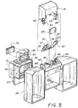
- FIG. 5 is an isometric, exploded view of the camera of the invention. Shown in the Figure is the mount 22, into which is incorporated components including the lens/shutter assembly housing 12, the front viewfinder element 14, the light baffle cone 25 and the lens/shutter assembly, not shown in the Figure.
- mount-return biasing means comprising springs 42 which are anchored to the stationary frame of the camera 26 by means of tabs 48, or by equivalent structure. While two return springs are shown, more or less than that number could be employed.
- flash unit 16 pivotal about ninety degrees around flash unit pivot pins 28 positioned in pivot pin bearings 44.
- a rear viewfinder element 24 is positionable in frame 26 as shown.
- the camera encasement 18, not shown in the Figure, is positionable around frame 26, and may be snapped or screwed thereto to provide an integral structure.
Landscapes
- Physics & Mathematics (AREA)
- General Physics & Mathematics (AREA)
- Stroboscope Apparatuses (AREA)
- Structure And Mechanism Of Cameras (AREA)
Claims (7)
- Appareil de prise de vues (10) comprenant un boîtier d'appareil photographique (18), une unité à lampe-éclair (16) pouvant être déplacée entre une position d'utilisation dans laquelle l'unité à lampe-éclair s'étend hors du boîtier et une position de rangement dans laquelle l'unité à lampe-éclair se trouve dans le boîtier, un ensemble objectif/obturateur (13), un viseur (14, 24), et- une monture mobile (22) supportant au moins une partie dudit ensemble objectif/obturateur et un composant avant (14) dudit viseur, ladite monture pouvant être déplacée entre une position de rangement, destinée à protéger le composant avant de l'ensemble objectif/obturateur, et une position fonctionnelle, mettant en place ledit ensemble objectif/obturateur et ledit composant avant pour permettre la prise de vues,- des moyens de sollicitation de la monture (20, 36) destinés à solliciter ladite monture (22) depuis la position de rangement jusqu'à la position fonctionnelle suite au déplacement de ladite unité à lampe-éclair (16) jusqu'à la position d'utilisation, et destinés à solliciter ladite monture (22) depuis la position fonctionnelle jusqu'à la position de rangement suite au déplacement de ladite unité à lampe-éclair (16) jusqu'à sa position de rangement, dans lequel,- l'unité à lampe-éclair (16) est munie d'un bras pivotant (29),caractérisé en ce que- les moyens de sollicitation de la monture comprennent des moyens de levier (20, 36) situés dans le boîtier d'appareil photographique (18),- le bras pivotant (29) et les moyens de levier (20, 36) sont disposés de façon que, lorsque l'unité à lampe-éclair (16) est amenée à sa position d'utilisation, le bras pivotant force les moyens de levier contre la monture mobile (22), en la déplaçant, ainsi que l'élément avant de viseur (14), vers l'avant de l'appareil photographique, en faisant simultanément sortir de l'avant de l'appareil photographique l'ensemble objectif/obturateur (13), et que, lorsque l'unité à lampe-éclair (16) est amenée à sa position de rangement, le bras pivotant pousse les moyens de levier à l'écart de la monture mobile (22), ce qui permet aux moyens de sollicitation de solliciter la monture mobile pour qu'elle recule en position de rangement dans le boîtier, et que l'élément de viseur se déplace vers l'arrière de l'appareil photographique, et- l'élément avant du viseur (14), lorsque la monture mobile (22) est dans sa position fonctionnelle, occupe un évidement (15), ménagé à l'intérieur du boîtier d'appareil photographique (18), qui est occupé par l'unité à lampe-éclair (16) lorsqu'elle est dans sa position de rangement.
- Appareil de prise de vues selon la revendication 1, caractérisé en ce que le bras pivotant de l'unité à lampe-éclair (16) comporte un premier moyen de commande par came (34) et les moyens de levier dudit moyen de sollicitation de la monture (20, 35) comportent un second moyen de commande par came (32) destiné à venir en prise avec ledit premier moyen de commande par came, ledit premier moyen de commande par came attaquant ledit second moyen de commande par came pour déplacer lesdits moyens de sollicitation de la monture vers la position d'utilisation lorsque l'on fait pivoter l'unité à lampe-éclair jusqu'à sa position d'utilisation.
- Appareil de prise de vues selon la revendication 2, caractérisé en ce que ledit premier moyen de commande par came comprend des contre-cames (34) dans l'unité à lampe-éclair (16), et les moyens de levier desdits moyens de sollicitation de la monture comprennent un levier d'actionnement monté sur pivot (20) comportant ledit second moyen de commande par came, ledit second moyen de commande par came comprenant des fentes de guidage de came (32) dans ledit levier, destinées à recevoir lesdites contre-cames (34), lesdites contre-cames poussant ledit levier d'actionnement monté sur pivot (20) afin de déplacer ladite monture mobile (22) jusqu'à la position fonctionnelle suite au pivotement de l'unité à lampe-éclair (16) jusqu'à la position d'utilisation.
- Appareil de prise de vues selon la revendication 2, caractérisé en ce que lesdits moyens de sollicitation de la monture comprennent en outre des moyens à ressort (42) destinés à pousser ladite monture (22) vers la position de rangement.
- Appareil de prise de vues selon la revendication 4, caractérisé en ce que lesdits moyens à ressort comprennent au moins un ressort à boudin (42) relié à ladite monture et au boîtier de l'appareil de prise de vues.
- Appareil de prise de vues selon la revendication 1, caractérisé en ce que ladite monture (22) porte une chambre noire (25).
- Appareil de prise de vues selon la revendication 1, caractérisé en ce que ladite monture (22) comprend un logement d'objectif/obturateur (12) destiné à enfermer au moins partiellement ledit ensemble objectif/obturateur (13).
Applications Claiming Priority (2)
| Application Number | Priority Date | Filing Date | Title |
|---|---|---|---|
| US07/859,993 US5255033A (en) | 1992-03-30 | 1992-03-30 | Folding camera |
| US859993 | 1992-03-30 |
Publications (2)
| Publication Number | Publication Date |
|---|---|
| EP0563658A1 EP0563658A1 (fr) | 1993-10-06 |
| EP0563658B1 true EP0563658B1 (fr) | 1997-05-14 |
Family
ID=25332250
Family Applications (1)
| Application Number | Title | Priority Date | Filing Date |
|---|---|---|---|
| EP93104104A Expired - Lifetime EP0563658B1 (fr) | 1992-03-30 | 1993-03-13 | Caméra pliable |
Country Status (4)
| Country | Link |
|---|---|
| US (1) | US5255033A (fr) |
| EP (1) | EP0563658B1 (fr) |
| JP (1) | JPH0643535A (fr) |
| DE (1) | DE69310597T2 (fr) |
Families Citing this family (11)
| Publication number | Priority date | Publication date | Assignee | Title |
|---|---|---|---|---|
| US5613170A (en) * | 1993-03-26 | 1997-03-18 | Fuji Photo Optical Co., Ltd. | Camera with novel exposure frame |
| JPH07114065A (ja) * | 1993-10-19 | 1995-05-02 | Fuji Photo Optical Co Ltd | カメラのファインダの視度自動調節装置 |
| EP0683421B1 (fr) | 1994-05-18 | 2001-10-04 | Fuji Photo Film Co., Ltd. | Emballage de film photographique et flash électronique associé |
| US5515126A (en) * | 1994-09-28 | 1996-05-07 | Eastman Kodak Company | Convertible flash camera and method |
| US5546147A (en) * | 1994-11-30 | 1996-08-13 | Eastman Kodak Company | Lens deployment mechanism for compact camera |
| US6554497B2 (en) | 1998-01-28 | 2003-04-29 | Fuji Photo Film Co., Ltd. | Compact camera |
| TW420767B (en) * | 1998-01-28 | 2001-02-01 | Fuji Photo Film Co Ltd | Compact camera |
| US6304728B1 (en) * | 2000-03-14 | 2001-10-16 | Concord Camera Corp. | Camera with flash unit disposed in between viewfinder lenses |
| USD448039S1 (en) | 2000-07-25 | 2001-09-18 | Fuji Photo Film Co., Ltd. | Camera |
| DE102004062731A1 (de) | 2004-06-04 | 2005-12-29 | Continental Teves Ag & Co. Ohg | Scheibenbremse mit Federanordung |
| JP6132430B2 (ja) * | 2013-04-04 | 2017-05-24 | 三星電子株式会社Samsung Electronics Co.,Ltd. | カメラ装置及びそれを備えた無線通信端末 |
Family Cites Families (16)
| Publication number | Priority date | Publication date | Assignee | Title |
|---|---|---|---|---|
| DE1192040B (de) * | 1963-05-18 | 1965-04-29 | Agfa Ag | Fotografische Kamera mit einem Einbaublitzlichtgeraet |
| JPS5347946Y2 (fr) * | 1974-08-13 | 1978-11-16 | ||
| US4016580A (en) * | 1975-04-21 | 1977-04-05 | Polaroid Corporation | Folding viewfinding and flash mounting assembly |
| JPS52110028A (en) * | 1976-03-12 | 1977-09-14 | Canon Inc | Camera |
| JPS5553321A (en) * | 1978-10-17 | 1980-04-18 | Konishiroku Photo Ind Co Ltd | Camera |
| DE2940301C2 (de) * | 1979-10-04 | 1982-05-13 | Agfa-Gevaert Ag, 5090 Leverkusen | Fotografische Kamera mit einem Elektronenblitzgerät |
| US4331404A (en) * | 1980-10-06 | 1982-05-25 | Polaroid Corporation | Hand held camera having protectable and balanced switching arrangement |
| US4452519A (en) * | 1982-12-16 | 1984-06-05 | Polaroid Corporation | Folding camera having erectable light source |
| JPS59210426A (ja) * | 1983-05-14 | 1984-11-29 | Nippon Kogaku Kk <Nikon> | 閃光装置内蔵カメラ |
| US4508440A (en) * | 1983-09-22 | 1985-04-02 | Polaroid Corporation | Bellows shielding structure |
| JPS6059234U (ja) * | 1983-09-30 | 1985-04-24 | 富士写真フイルム株式会社 | 折畳み式カメラの自動収納型ストロボ発光装置 |
| DE8336141U1 (de) * | 1983-12-16 | 1984-03-15 | Kodak Ag, 7000 Stuttgart | Kleinbildkamera kompakter bauart |
| DE3639751C3 (de) * | 1985-11-22 | 2000-06-29 | Asahi Optical Co Ltd | Einäugige Spiegelreflexkamera |
| US4819016A (en) * | 1988-03-16 | 1989-04-04 | Eastman Kodak Company | Photographic camera |
| US5084721A (en) * | 1991-03-15 | 1992-01-28 | Eastman Kodak Company | Folding dual lens camera |
| US5151728A (en) * | 1991-08-01 | 1992-09-29 | Polaroid Corporation | 6-bar erecting system |
-
1992
- 1992-03-30 US US07/859,993 patent/US5255033A/en not_active Expired - Fee Related
-
1993
- 1993-03-13 EP EP93104104A patent/EP0563658B1/fr not_active Expired - Lifetime
- 1993-03-13 DE DE69310597T patent/DE69310597T2/de not_active Expired - Fee Related
- 1993-03-30 JP JP5072016A patent/JPH0643535A/ja not_active Withdrawn
Also Published As
| Publication number | Publication date |
|---|---|
| DE69310597D1 (de) | 1997-06-19 |
| JPH0643535A (ja) | 1994-02-18 |
| EP0563658A1 (fr) | 1993-10-06 |
| US5255033A (en) | 1993-10-19 |
| DE69310597T2 (de) | 1997-12-11 |
Similar Documents
| Publication | Publication Date | Title |
|---|---|---|
| EP0563658B1 (fr) | Caméra pliable | |
| US4557571A (en) | Compact camera with flash unit | |
| EP0556755B1 (fr) | Appareil photographique compact avec couvre-objectif | |
| CA2025394A1 (fr) | Viseur optique pour appareil-photo a flash escamotable | |
| EP0515497B1 (fr) | Appareil photographique a unite de flash relevable | |
| US5146253A (en) | Photographic camera with collapsible optical devices | |
| US5084721A (en) | Folding dual lens camera | |
| US4996548A (en) | Camera with flip-up flash unit | |
| EP0588226B1 (fr) | Monture de lentille d'un viseur pour une caméra compacte à unité de flash/viseur relevable | |
| EP0521351B1 (fr) | Viseur éjectable pour un appareil photographique à unité de flash relevable | |
| US3967303A (en) | Accessory attachment for cameras | |
| US4074296A (en) | Folding camera | |
| US5255032A (en) | Compact camera with deployable flash unit | |
| US3962711A (en) | Accessory adapter for photographic apparatus | |
| US5253002A (en) | Compact camera with deployable flash unit | |
| US3967302A (en) | Accessory attachment for photographic apparatus | |
| GB2106261A (en) | Camera having integral flash | |
| US4245903A (en) | Photographic camera | |
| US4086606A (en) | Strobe camera with flat capacitor | |
| US6002889A (en) | Camera with built-in deployable support | |
| JPS59165039A (ja) | 可変焦点カメラ | |
| US5613169A (en) | Compact camera with unexposed-film storage slot surrounding flash receiving pocket for flip-up flash unit | |
| EP0557683A1 (fr) | Caméra compacte munie d'une unité de flash intégrée | |
| US4179205A (en) | Strobe-light apparatus for use with photographic camera | |
| JPH0272338A (ja) | カード状カメラ |
Legal Events
| Date | Code | Title | Description |
|---|---|---|---|
| PUAI | Public reference made under article 153(3) epc to a published international application that has entered the european phase |
Free format text: ORIGINAL CODE: 0009012 |
|
| AK | Designated contracting states |
Kind code of ref document: A1 Designated state(s): BE CH DE ES FR GB IT LI NL |
|
| 17P | Request for examination filed |
Effective date: 19940319 |
|
| 17Q | First examination report despatched |
Effective date: 19950808 |
|
| GRAG | Despatch of communication of intention to grant |
Free format text: ORIGINAL CODE: EPIDOS AGRA |
|
| GRAG | Despatch of communication of intention to grant |
Free format text: ORIGINAL CODE: EPIDOS AGRA |
|
| GRAH | Despatch of communication of intention to grant a patent |
Free format text: ORIGINAL CODE: EPIDOS IGRA |
|
| GRAH | Despatch of communication of intention to grant a patent |
Free format text: ORIGINAL CODE: EPIDOS IGRA |
|
| GRAA | (expected) grant |
Free format text: ORIGINAL CODE: 0009210 |
|
| AK | Designated contracting states |
Kind code of ref document: B1 Designated state(s): DE |
|
| REF | Corresponds to: |
Ref document number: 69310597 Country of ref document: DE Date of ref document: 19970619 |
|
| EN | Fr: translation not filed | ||
| PLBE | No opposition filed within time limit |
Free format text: ORIGINAL CODE: 0009261 |
|
| PGFP | Annual fee paid to national office [announced via postgrant information from national office to epo] |
Ref country code: DE Payment date: 19980330 Year of fee payment: 6 |
|
| 26N | No opposition filed | ||
| PG25 | Lapsed in a contracting state [announced via postgrant information from national office to epo] |
Ref country code: DE Free format text: LAPSE BECAUSE OF NON-PAYMENT OF DUE FEES Effective date: 20000101 |