EP0563792A2 - Verfahren und Vorrichtung für Sauerstoff-Brennstoffheizung mit reduziertem NOx in korrosiven Hochtemparturumgebungen - Google Patents
Verfahren und Vorrichtung für Sauerstoff-Brennstoffheizung mit reduziertem NOx in korrosiven Hochtemparturumgebungen Download PDFInfo
- Publication number
- EP0563792A2 EP0563792A2 EP93104938A EP93104938A EP0563792A2 EP 0563792 A2 EP0563792 A2 EP 0563792A2 EP 93104938 A EP93104938 A EP 93104938A EP 93104938 A EP93104938 A EP 93104938A EP 0563792 A2 EP0563792 A2 EP 0563792A2
- Authority
- EP
- European Patent Office
- Prior art keywords
- burner
- flame
- fuel
- length
- passage
- Prior art date
- Legal status (The legal status is an assumption and is not a legal conclusion. Google has not performed a legal analysis and makes no representation as to the accuracy of the status listed.)
- Withdrawn
Links
Images


Classifications
-
- F—MECHANICAL ENGINEERING; LIGHTING; HEATING; WEAPONS; BLASTING
- F23—COMBUSTION APPARATUS; COMBUSTION PROCESSES
- F23D—BURNERS
- F23D14/00—Burners for combustion of a gas, e.g. of a gas stored under pressure as a liquid
- F23D14/32—Burners for combustion of a gas, e.g. of a gas stored under pressure as a liquid using a mixture of gaseous fuel and pure oxygen or oxygen-enriched air
-
- C—CHEMISTRY; METALLURGY
- C03—GLASS; MINERAL OR SLAG WOOL
- C03B—MANUFACTURE, SHAPING, OR SUPPLEMENTARY PROCESSES
- C03B5/00—Melting in furnaces; Furnaces so far as specially adapted for glass manufacture
- C03B5/16—Special features of the melting process; Auxiliary means specially adapted for glass-melting furnaces
- C03B5/235—Heating the glass
- C03B5/2353—Heating the glass by combustion with pure oxygen or oxygen-enriched air, e.g. using oxy-fuel burners or oxygen lances
-
- F—MECHANICAL ENGINEERING; LIGHTING; HEATING; WEAPONS; BLASTING
- F23—COMBUSTION APPARATUS; COMBUSTION PROCESSES
- F23C—METHODS OR APPARATUS FOR COMBUSTION USING FLUID FUEL OR SOLID FUEL SUSPENDED IN A CARRIER GAS OR AIR
- F23C3/00—Combustion apparatus characterised by the shape of the combustion chamber
-
- F—MECHANICAL ENGINEERING; LIGHTING; HEATING; WEAPONS; BLASTING
- F23—COMBUSTION APPARATUS; COMBUSTION PROCESSES
- F23D—BURNERS
- F23D14/00—Burners for combustion of a gas, e.g. of a gas stored under pressure as a liquid
- F23D14/20—Non-premix gas burners, i.e. in which gaseous fuel is mixed with combustion air on arrival at the combustion zone
- F23D14/22—Non-premix gas burners, i.e. in which gaseous fuel is mixed with combustion air on arrival at the combustion zone with separate air and gas feed ducts, e.g. with ducts running parallel or crossing each other
-
- F—MECHANICAL ENGINEERING; LIGHTING; HEATING; WEAPONS; BLASTING
- F23—COMBUSTION APPARATUS; COMBUSTION PROCESSES
- F23D—BURNERS
- F23D2900/00—Special features of, or arrangements for burners using fluid fuels or solid fuels suspended in a carrier gas
- F23D2900/00004—Burners specially adapted for generating high luminous flames, e.g. yellow for fuel-rich mixtures
-
- Y—GENERAL TAGGING OF NEW TECHNOLOGICAL DEVELOPMENTS; GENERAL TAGGING OF CROSS-SECTIONAL TECHNOLOGIES SPANNING OVER SEVERAL SECTIONS OF THE IPC; TECHNICAL SUBJECTS COVERED BY FORMER USPC CROSS-REFERENCE ART COLLECTIONS [XRACs] AND DIGESTS
- Y02—TECHNOLOGIES OR APPLICATIONS FOR MITIGATION OR ADAPTATION AGAINST CLIMATE CHANGE
- Y02E—REDUCTION OF GREENHOUSE GAS [GHG] EMISSIONS, RELATED TO ENERGY GENERATION, TRANSMISSION OR DISTRIBUTION
- Y02E20/00—Combustion technologies with mitigation potential
- Y02E20/34—Indirect CO2mitigation, i.e. by acting on non CO2directly related matters of the process, e.g. pre-heating or heat recovery
-
- Y—GENERAL TAGGING OF NEW TECHNOLOGICAL DEVELOPMENTS; GENERAL TAGGING OF CROSS-SECTIONAL TECHNOLOGIES SPANNING OVER SEVERAL SECTIONS OF THE IPC; TECHNICAL SUBJECTS COVERED BY FORMER USPC CROSS-REFERENCE ART COLLECTIONS [XRACs] AND DIGESTS
- Y02—TECHNOLOGIES OR APPLICATIONS FOR MITIGATION OR ADAPTATION AGAINST CLIMATE CHANGE
- Y02P—CLIMATE CHANGE MITIGATION TECHNOLOGIES IN THE PRODUCTION OR PROCESSING OF GOODS
- Y02P40/00—Technologies relating to the processing of minerals
- Y02P40/50—Glass production, e.g. reusing waste heat during processing or shaping
-
- Y—GENERAL TAGGING OF NEW TECHNOLOGICAL DEVELOPMENTS; GENERAL TAGGING OF CROSS-SECTIONAL TECHNOLOGIES SPANNING OVER SEVERAL SECTIONS OF THE IPC; TECHNICAL SUBJECTS COVERED BY FORMER USPC CROSS-REFERENCE ART COLLECTIONS [XRACs] AND DIGESTS
- Y02—TECHNOLOGIES OR APPLICATIONS FOR MITIGATION OR ADAPTATION AGAINST CLIMATE CHANGE
- Y02P—CLIMATE CHANGE MITIGATION TECHNOLOGIES IN THE PRODUCTION OR PROCESSING OF GOODS
- Y02P40/00—Technologies relating to the processing of minerals
- Y02P40/50—Glass production, e.g. reusing waste heat during processing or shaping
- Y02P40/57—Improving the yield, e-g- reduction of reject rates
Definitions
- the present invention pertains to oxygen-fuel heating processes and apparatus used for producing elevated temperatures in industrial melting furnaces for such diverse products as metals, glass, ceramic materials and the like.
- Another and more efficient method is using oxygen in the combustion process to eliminate nitrogen from the air and reduce the NO x and particulate emissions to below the guidelines suggested by the Environmental Protection Agency.
- oxygen in combustion reduces carbon dioxide emission through an increase in heating efficiency of the furnace and brings numerous other benefits ranging from increased production capacity to savings in batch chemicals.
- Oxygen-fuel burners may be divided into two major groups, those that are water cooled and those that are gas cooled.
- a frequently en-countered problem with the burners of ether group is the lack of a diluent and carrier gas, e.g., nitrogen, which increases partial pressures of volatile batch components and accelerates corrosion rates of metallic and ceramic materials used for burner construction.
- a diluent and carrier gas e.g., nitrogen
- build-up and corrosion on water or gas cooled burner nozzles are the most common problems in high temperature furnaces.
- a large temperature difference between the cooled burner nozzles and furnace gases causes condensation of volatile and corrosive species and build-up on the burner nozzle. This is reported in an article entitled "Oxygen Firing at Parkersburg" by D. Shamp and D. Davis in the December 1990 edition of American Glass Review.
- building on the nozzles can cause flame deflection and im-pingement on the burner nozzle leading to damage or destruction of the burner.
- a second problem encountered with water and gas cooled oxy-fuel burners is the fact that the refractory burner block, often used to enable installation of the burner into a furnace and/or to increase flame stability, involves an opening with an inner diameter much larger than the flame jet diameter causing entrainment of corrosive furnace gases or particulate material inside the block and contact with the burner.
- This type of burner is shown in U.S. Patent 4,690,634.
- water cooled oxy-fuel burners require capital investment and maintenance. Such burners may lower the overall heating efficiency of a furnace by extracting considerable heat from it with the flow of cooling water. For example, for a burner cooling water flow rate of 5 gallons per minute, and output to input water temperature difference of 50°F, heat loss per burner is approximately 125,000 Btu's per hour. For a 10-burner furnace the heat loss due to the water-cooling amounts to about $30,000 per year. In addition, there is always the possibility of water leakage into the furnace if a burner is not maintained properly and there is a risk of clogging and corrosion of the burner water cooling channels if poor water quality is the only means of cooling available to the user.
- Gas-cooled oxy-fuel burners can present a problem in the case of interruption in the fuel or oxygen supply. Such burners have to be immediately removed from the firing port in the furnace to prevent possible damage from the high temperature present in the furnace. If such burners rely upon metal fins at the burner face to cool the burner, these fins can collect condensation and result in corrosion problems with the burner.
- the present invention pertains to a method and apparatus for utilizing oxy-fuel heating in a high temperature production furnace such as a glass melting furnace.
- the flame is created by shielding a fuel rich oxy-fuel flame inside of a sheath of a fuel lean or oxygen rich oxy-fuel flame and confining the shielding of the flame along a predetermined path having a predetermined cross-section to achieve the results of two phase turbulent diffusion flame production in a precombustor so that aspiration of corrosive species leading to burner destruction is prevented and generation of NO x is reduced.
- Figures 1a, 1b, and 1c are schematic representations of prior art oxy-fuel burners and the burner block used to mount the burner into the heating furnace showing respectively, a diverging burner block nozzle, a large diameter cylindrical nozzle and a small diameter cylindrical nozzle.
- Figures 2a and 2b are schematic representations of a prior art oxy-fuel burner and burner block of the diverging type showing the effect of velocity on the flame shape.
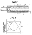
- Figure 3 is a schematic representation of the apparatus of the present invention.
- Figure 4 is a plot of distance from the centerline to radially opposed points on the inner surface of the precombustor of the present invention against the concentrations of oxy-fuel mixtures in the precombustor.
- oxy or oxygen is taken to mean any gaseous oxidizer having more than 30% oxygen.
- oxy or oxygen-fuel includes all oxidizers except air.
- fuels are taken to mean the normally gaseous fuels including, but not limited to, methane, natural gas, propane and the like, as well as liquid fuels, such as fuel oils, heating oils, waste oils, slurries, and the like, to name but a few.
- prior art burners could employ an oxy-fuel burner 10, 12 or 14 and a diverging 16, large diameter cylindrical 18 or small diameter cylindrical 20 burner block.
- the flame shape 22, 24 and 26 is generally the same.
- the shape of the nozzle causes aspiration of atmosphere contained inside the furnace into the flame as shown by the arrows 28 and 30 respectively. This is also discussed in the text of U.S. Patent 4,690,635.
- the larger diameter opening in the burner blocks 16, 18 in combination with high fuel and/or oxygen jet velocities used to keep the high temperature flame away from the metallic or refractory burner materials induces a substantial recirculation and entrainment of the furnace gases and particulates into the burner blocks causing build-up and corrosion as discussed by patentees in U.S. Patents 4,378,205 and 4,541,796.
- the build-up in the burner blocks can alter flame direction, shape and stability and may result in localized increase in flame temperatures and rapid destruction of the burner.
- build-up or constriction in a nozzle exit area may cause undesirable pressure increase in the input gas. In zone-control furnaces, this pressure imbalance could cause uneven heat distribution to the load as well as control difficulties.
- low flame luminosity is typical for oxygen-natural gas burners because of the high burning velocity and rapid mixing rates of such combustion systems. This decreases the heating efficiency since radiation is the major heat transfer mechanism in a high temperature furnace such as a glass melter.
- a non-luminous flame 36 is produced.
- the non-luminous flame 36 will be less efficient in heating the furnace and the materials therein because of the inherent poor heat transfer characteristics as discussed above. If the burner 32 procedure a low momentum oxy-fuel flame, the flame 36 becomes luminous but at the same time the flame will tend to lift toward the roof of the furnace or vessel being heated as shown in Figure 2b. Allowing the flame to lift and thereby cause localized heating will seriously decrease the life of the roof refractories in a melting device such as the furnace crown in a conventional glass melting furnace or glass melter.
- Flame 47 comprises a core 48 of a fuel rich oxy-fuel mixture surrounded by a sheath of a fuel lean or oxygen rich mixture 50.
- the geometry of the precombustor 52 is a function of the firing rate.
- the dimensions of the precombustor 52 should be such that the distance or length from the face of the burner 44 to the discharge end 54 of the precombustor 52 is between 6 inches and 48 inches, the diameter of the interior cylindrical aperture or passage of the precombustor 52 should be between 2 inches and 8 inches and the ratio of length to diameter (L/d) should be between 2 and 6.
- the preferred precombustor configurations are shown in Table 1 below.
- the numbers given in the table above are empirical values derived from the measurements of flame luminosity, precombustor temperature profile, and precombustor pressure collected during experimental test firing. These dimensions go against the traditional approaches in designing burners and burner blocks since this "tight" precombustor is actually cooled and shielded by the flowing and reacting gases. As used herein "tight” refers to a small clearance between the outer diameter of the flame 47 and the inner diameter of the precombustor 52. In the prior art, the burner blocks were large to keep them away from the hot oxy/fuel flame which resulted in the entrainment of the furnaces gases.
- the precombustor can have a converging or diverging shape to the inner surface 56, provided that the angle of convergence or divergence is no greater than plus or minus 15°, the angle being measured relative to the longitudinal axis of the precombustor 52.
- the angle is shown as ⁇ in Figure 3 of the drawing.
- the present invention enables formation and stabilization of a two-phase turbulent diffusion flame and its introduction into a furnace without any aspiration of the furnace gases into the precombustor 52.
- the flame 47 is stabilized within the precombustor 52 and extends into a furnace (not shown) through the projecting end 54 of the precombustor 52.
- the center core 48 (fuel rich phase) of the flame 47 is luminous and at high temperature and does not come into contact with the walls 56 of the precombustor 52.
- the cooler annular sheath 50 or oxygen-rich place surrounds the luminous center core 48 of the flame 47, cools and protects the precombustor 52 walls 56 from high flame temperatures and prevents any aspiration of furnace gases into the precombustor 52.
- the products of combustion from this two-phase flame include soot particles which were produced by fuel cracking and gas phase nucleation process within the precombustor 52. Oxidation of soot with remaining fuel inside the furnace gives a very luminous flame suitable for efficient radiative heat transfer to the article or load being heated.
- the nozzle velocities e.g. the velocity at the face 44 of the burner 40 of natural gas (v ng ) and oxygen (v ox ) should not be higher than about 600 feet per second, and the ratio of V ng /V ox should be between 0.3 and 6.0.
- the high flame luminosity when using the apparatus of the present invention lower velocities should be used, with the V ng /V ox ratio being between 1.0 and 1.5.
- the precombustor may be further divided into the high momentum and low momentum version which would correspond to the high and low and specified velocity ranges.
- the precombustor can be used where the burner is fired outside of the stoichiometric ratio, for example in a staged combustion process.
- oxygen/natural gas is less than 1/1
- oxygen and fuel may be introduced in a reversed configuration and the fuel flow used for the precombustor cooling.
- the precombustor 52 of the present invention operates at lower temperatures than those typically found in a high temperature furnace. This being a surprising result gives the burner or furnace operator a wide latitude since no special materials are required except those compatible with the materials normally used in construction of a given furnace.
- a precombustor where the L/d ratio is less than 2, the diameter of the precombustor becomes too large which does not permit production of the two-phase flame within the precombustor.
- high nozzle velocities are needed to prevent the flame from curving up and overheating the furnace roof refractories such as shown in Figure 2B.
- a high turbulent flow is required causing intense oxygen-fuel mixing, high flame temperatures and aspiration of furnace gases into the combustor. This would be the case if the precombustor was used as a conventional small diameter burner block such as shown in Figure 1c.
- the precombustor diameter is too small or the length is too large which leads to unacceptably high flame temperature within the precombustor. This also may induce too large a temperature gradient between the ends of the precombustor and promote crack propagation within the material of construction of the precombustor 52.
- a device according to the present invention was tested where the precombustor 52 had a passage with an L/d ratio of 3.2. Temperature of the furnace into which the precombustor was installed was maintained at about 2400°F for a twenty-four hour time period. During the test, temperature of several burner components (e.g. nozzle, mounting plate, precombustor) were monitored. In addition, pressure in the back of the burner block was measured. The recorded temperatures under steady state conditions of a firing rate of 1.6 million Btu per hour were: an average furnace temperature of 2,410°F, an average precombustor temperature at the nozzle end 44 of 1,580°F and at the discharge end 54 or furnace end 1,970°F.
- burner components e.g. nozzle, mounting plate, precombustor
- Static pressure measured in back of the precombustor was above atmospheric for firing rates above 1 million Btu per hour. This indicates that there was no aspiration of furnace gases into the precombustor, since the furnace was operated at a slightly negative pressure. Flame luminosity was high up to 3 million Btu per hour above which it gradually decreased.
- precombustor being an L/d of 4 fabricated of the same material as furnace walls was tested in a fully oxygen/natural gas fired fiberglass melting furnace.
- the precombustor was installed near the batch charge side through a furnace wall which was at 2,204°F temperature before the start of the test.
- the temperature of the precombustor face and the surrounding furnace wall refractories decreased by about 50°F several hours after the start of firing, thus demonstrating the effectiveness of oxygen cooling and protecting furnace refractories.
- Flame luminosity was high up to a firing rate of 1.5 million Btu per hour.
- the precombustor was inspected and found to be clean, without any signs of corrosion or deposition on the face or walls of the inner chamber.
- the nozzle of the burner used for injection of natural gas and oxygen was also found to be without any signs of build-up or corrosion.
Landscapes
- Engineering & Computer Science (AREA)
- Chemical & Material Sciences (AREA)
- Combustion & Propulsion (AREA)
- Mechanical Engineering (AREA)
- General Engineering & Computer Science (AREA)
- Materials Engineering (AREA)
- Organic Chemistry (AREA)
- Pressure-Spray And Ultrasonic-Wave- Spray Burners (AREA)
Applications Claiming Priority (2)
| Application Number | Priority Date | Filing Date | Title |
|---|---|---|---|
| US07/860,652 US5256058A (en) | 1992-03-30 | 1992-03-30 | Method and apparatus for oxy-fuel heating with lowered NOx in high temperature corrosive environments |
| US860652 | 1992-03-30 |
Publications (2)
| Publication Number | Publication Date |
|---|---|
| EP0563792A2 true EP0563792A2 (de) | 1993-10-06 |
| EP0563792A3 EP0563792A3 (en) | 1993-12-08 |
Family
ID=25333700
Family Applications (1)
| Application Number | Title | Priority Date | Filing Date |
|---|---|---|---|
| EP19930104938 Withdrawn EP0563792A3 (en) | 1992-03-30 | 1993-03-25 | Method and apparatus for oxy-fuel heating with lowered nox in high temperature corrosive environments |
Country Status (10)
| Country | Link |
|---|---|
| US (2) | US5256058A (de) |
| EP (1) | EP0563792A3 (de) |
| JP (1) | JPH0642722A (de) |
| KR (1) | KR970009482B1 (de) |
| CA (1) | CA2092255C (de) |
| CZ (1) | CZ279526B6 (de) |
| MX (1) | MX9301730A (de) |
| MY (1) | MY109085A (de) |
| PL (1) | PL298305A1 (de) |
| TW (1) | TW244373B (de) |
Cited By (5)
| Publication number | Priority date | Publication date | Assignee | Title |
|---|---|---|---|---|
| EP0614044A3 (de) * | 1993-03-01 | 1994-11-09 | Air Prod & Chem | Verfahren und Vorrichtung zur mit durch Verbrennung verbesserten Zerstäubung und Verdampfung von flüssigen Brennstoffen. |
| EP0703410A1 (de) * | 1994-09-22 | 1996-03-27 | L'air Liquide, Societe Anonyme Pour L'etude Et L'exploitation Des Procedes Georges Claude | Brennerstein für Sauerstoff-Brennstoff-Brenner, Brenner mit einem solchen Brennerstein und Verfahren zur Verwendung |
| DE19855069A1 (de) * | 1998-11-28 | 2000-05-31 | Asea Brown Boveri | Flüssigbrennstoffaufbereitungseinheit für einen Brenner und Verfahren zum Betrieb derselben |
| DE102005005735A1 (de) * | 2005-02-07 | 2006-08-10 | Air Liquide Deutschland Gmbh | Verfahren zum Erhitzen eines Industrieofens unter Einsatz eines Brenners und zur Durchführung des Verfahrens geeigneter Rohr-in-Rohr-Brenner |
| EP2392857A1 (de) * | 2010-06-07 | 2011-12-07 | L'Air Liquide Société Anonyme pour l'Etude et l'Exploitation des Procédés Georges Claude | Sauerstoff-Brennstoff-Brenner |
Families Citing this family (51)
| Publication number | Priority date | Publication date | Assignee | Title |
|---|---|---|---|---|
| US5256058A (en) * | 1992-03-30 | 1993-10-26 | Combustion Tec, Inc. | Method and apparatus for oxy-fuel heating with lowered NOx in high temperature corrosive environments |
| US5267850A (en) * | 1992-06-04 | 1993-12-07 | Praxair Technology, Inc. | Fuel jet burner |
| US5449286A (en) * | 1993-06-22 | 1995-09-12 | Praxair Technology, Inc. | Controlled flame fuel jet combustion |
| US5387100A (en) * | 1994-02-17 | 1995-02-07 | Praxair Technology, Inc. | Super off-stoichiometric combustion method |
| US5725366A (en) * | 1994-03-28 | 1998-03-10 | Institute Of Gas Technology | High-heat transfer, low-nox oxygen-fuel combustion system |
| EP0683357B1 (de) | 1994-05-18 | 2000-03-01 | Praxair Technology, Inc. | Verfahren zum Betrieb eines Ofens |
| US5575637A (en) * | 1994-11-04 | 1996-11-19 | Air Products And Chemicals, Inc. | Method and device for low-NOx high efficiency heating in high temperature furnaces |
| US5545031A (en) * | 1994-12-30 | 1996-08-13 | Combustion Tec, Inc. | Method and apparatus for injecting fuel and oxidant into a combustion burner |
| US5725367A (en) * | 1994-12-30 | 1998-03-10 | Combustion Tec, Inc. | Method and apparatus for dispersing fuel and oxidant from a burner |
| US5567141A (en) * | 1994-12-30 | 1996-10-22 | Combustion Tec, Inc. | Oxy-liquid fuel combustion process and apparatus |
| US5984667A (en) * | 1995-07-17 | 1999-11-16 | American Air Liquide, Inc. | Combustion process and apparatus therefore containing separate injection of fuel and oxidant streams |
| ES2220965T3 (es) * | 1995-07-17 | 2004-12-16 | L'air Liquide, S.A. A Directoire Et Conseil De Surv. Pour L'etude Et L'exploitat. Procedes G. Claude | Proceso de combustion y aparato para el mismo con inyeccion separada de las corrientes de combustible y oxidante. |
| US5611682A (en) * | 1995-09-05 | 1997-03-18 | Air Products And Chemicals, Inc. | Low-NOx staged combustion device for controlled radiative heating in high temperature furnaces |
| US5743723A (en) * | 1995-09-15 | 1998-04-28 | American Air Liquide, Inc. | Oxy-fuel burner having coaxial fuel and oxidant outlets |
| US6253578B1 (en) * | 1996-04-12 | 2001-07-03 | Praxair Technology, Inc. | Glass melting process and apparatus with reduced emissions and refractory corrosion |
| US5975886A (en) * | 1996-11-25 | 1999-11-02 | L'air Liquide, Societe Anonyme Pour L'etude Et L'exploitation Des Procedes Georges Claude | Combustion process and apparatus therefore containing separate injection of fuel and oxidant streams |
| US5931654A (en) * | 1997-06-30 | 1999-08-03 | Praxair Technology, Inc. | Recessed furnace lance purge gas system |
| EP0911583B1 (de) | 1997-10-27 | 2003-03-12 | ALSTOM (Switzerland) Ltd | Verfahren zum Betrieb eines Vormischbrenners |
| US6237369B1 (en) * | 1997-12-17 | 2001-05-29 | Owens Corning Fiberglas Technology, Inc. | Roof-mounted oxygen-fuel burner for a glass melting furnace and process of using the oxygen-fuel burner |
| US6029910A (en) * | 1998-02-05 | 2000-02-29 | American Air Liquide, Inc. | Low firing rate oxy-fuel burner |
| US5954498A (en) * | 1998-02-26 | 1999-09-21 | American Air Liquide, Inc. | Oxidizing oxygen-fuel burner firing for reducing NOx emissions from high temperature furnaces |
| EP0992661B1 (de) * | 1998-10-05 | 2003-12-03 | ALSTOM (Switzerland) Ltd | Zündbrenner für eine Brennkammer |
| US6123542A (en) * | 1998-11-03 | 2000-09-26 | American Air Liquide | Self-cooled oxygen-fuel burner for use in high-temperature and high-particulate furnaces |
| US6244854B1 (en) * | 1999-05-13 | 2001-06-12 | The Boc Group, Inc. | Burner and combustion method for the production of flame jet sheets in industrial furnaces |
| US6705117B2 (en) | 1999-08-16 | 2004-03-16 | The Boc Group, Inc. | Method of heating a glass melting furnace using a roof mounted, staged combustion oxygen-fuel burner |
| CA2323032A1 (en) | 1999-10-18 | 2001-04-18 | Air Products And Chemicals, Inc. | Method and apparatus for backing-up oxy-fuel combustion with air-fuel combustion |
| US6579085B1 (en) * | 2000-05-05 | 2003-06-17 | The Boc Group, Inc. | Burner and combustion method for the production of flame jet sheets in industrial furnaces |
| US6582218B1 (en) * | 2002-06-11 | 2003-06-24 | Air Products And Chemicals, Inc. | Self-cooling oxy-fuel through-port burner for protruding into glass furnace atmosphere |
| JP3653266B2 (ja) * | 2002-12-19 | 2005-05-25 | 山一金属株式会社 | 動植物油燃焼装置 |
| US6910431B2 (en) * | 2002-12-30 | 2005-06-28 | The Boc Group, Inc. | Burner-lance and combustion method for heating surfaces susceptible to oxidation or reduction |
| US20050252430A1 (en) * | 2002-12-30 | 2005-11-17 | Satchell Donald P Jr | Burner-lance and combustion method for heating surfaces susceptible to oxidation or reduction |
| US20040261676A1 (en) * | 2003-06-09 | 2004-12-30 | Choi Donald H | Utilization of exhaust heat for conversion of water to fuel |
| US20070218776A1 (en) * | 2006-03-20 | 2007-09-20 | American Water Heater Company, A Corporation Of The State Of Nevade | Fuel supply line connector for water heater mounting bracket |
| US20070221142A1 (en) * | 2006-03-20 | 2007-09-27 | American Water Heater Company, A Corporation Of The State Of Nevada | Ultra low NOx water heater |
| US20100159409A1 (en) * | 2006-06-05 | 2010-06-24 | Richardson Andrew P | Non-centric oxy-fuel burner for glass melting systems |
| US20070281264A1 (en) * | 2006-06-05 | 2007-12-06 | Neil Simpson | Non-centric oxy-fuel burner for glass melting systems |
| US8454354B2 (en) * | 2008-05-08 | 2013-06-04 | Air Products And Chemicals, Inc. | Highly radiative burner and combustion process |
| US20090325114A1 (en) * | 2008-06-27 | 2009-12-31 | Empire Comfort Systems, Inc. | Atmospheric Burner for Gas Log Fireplace Producing Stage Combustion and Yellow Chemiluminescent Flame |
| US8689710B2 (en) * | 2008-09-26 | 2014-04-08 | Air Products And Chemicals, Inc. | Combustion system with precombustor |
| WO2010036877A2 (en) * | 2008-09-26 | 2010-04-01 | Air Products And Chemicals, Inc. | Combustion system with precombustor for recycled flue gas |
| FR2941286B1 (fr) * | 2009-01-16 | 2012-08-31 | Air Liquide | Bruleur pilote air-gaz pouvant fonctionner a l'oxygene. |
| CN103782099B (zh) | 2011-02-16 | 2016-03-16 | 气体产品与化学公司 | 预混合空气-气体喷燃器的氧富化 |
| CA2827865C (en) | 2011-03-10 | 2016-01-05 | Air Products And Chemicals, Inc. | Oxy-fuel burner arrangement |
| EP2703339A1 (de) * | 2012-09-04 | 2014-03-05 | Casale Chemicals S.A. | Brenner zur Herstellung von Synthesegas |
| WO2015007252A1 (en) | 2013-07-15 | 2015-01-22 | Flammatec, Spol. S R.O. | The way of gas combustion in industrial furnaces and burner for realization of this method |
| EP3058300B1 (de) * | 2013-10-14 | 2018-12-05 | Bloom Engineering Company, Inc. | Brenneranschlussblockanordnung |
| US10859260B2 (en) | 2017-10-13 | 2020-12-08 | Praxair Technology, Inc. | Reduced fouling in staged combustion |
| WO2020131113A1 (en) | 2018-12-21 | 2020-06-25 | Selas Heat Technology Company Llc | Oxy forehearth burner assembly |
| US10845052B1 (en) | 2019-12-20 | 2020-11-24 | Jupiter Oxygen Corporation | Combustion system comprising an annular shroud burner |
| US12359807B2 (en) | 2019-12-20 | 2025-07-15 | Jupiter Oxygen Corporation | Combustion system comprising an annular shroud burner |
| CN112228870B (zh) * | 2020-10-20 | 2023-04-07 | 凯盛君恒有限公司 | 一种用于中性硼硅玻璃管成型的无焰燃烧器 |
Family Cites Families (16)
| Publication number | Priority date | Publication date | Assignee | Title |
|---|---|---|---|---|
| US2518025A (en) * | 1948-03-17 | 1950-08-08 | Surface Combustion Corp | Combination oil and gas burner |
| US3092166A (en) * | 1959-12-15 | 1963-06-04 | Air Reduction | Space heating method and apparatus |
| FR1441671A (fr) * | 1965-04-28 | 1966-06-10 | Air Liquide | Brûleur à flamme variable pour hydrocarbures gazeux notamment le gaz naturel |
| US3856457A (en) * | 1972-12-29 | 1974-12-24 | Air Prod & Chem | Burner of the oxy-fuel type |
| JPS5222131A (en) * | 1975-07-11 | 1977-02-19 | Henrii Haabei Edowaado | Fluid flow throttling device and it*s manufacturing method |
| US4378205A (en) * | 1980-04-10 | 1983-03-29 | Union Carbide Corporation | Oxygen aspirator burner and process for firing a furnace |
| US4541796A (en) * | 1980-04-10 | 1985-09-17 | Union Carbide Corporation | Oxygen aspirator burner for firing a furnace |
| JPS58221306A (ja) * | 1982-01-28 | 1983-12-23 | Tokyo Gas Co Ltd | 輝炎発生燃焼方法 |
| US4726763A (en) * | 1982-09-24 | 1988-02-23 | Gte Products Corporation | Dual insulated ceramic burner |
| JPS6229820A (ja) * | 1985-04-26 | 1987-02-07 | Nippon Kokan Kk <Nkk> | 直火還元加熱バ−ナ |
| EP0229048B1 (de) * | 1985-06-03 | 1990-11-07 | Asarco Incorporated | Gasbrenner |
| CN1007920B (zh) * | 1985-07-15 | 1990-05-09 | 美国氧化公司 | 烃类流体燃料燃烧、控制方法及装置 |
| US4690635A (en) * | 1986-07-21 | 1987-09-01 | Maxon Corporation | High temperature burner assembly |
| SE455438B (sv) * | 1986-11-24 | 1988-07-11 | Aga Ab | Sett att senka en brennares flamtemperatur samt brennare med munstycken for oxygen resp brensle |
| US5100313A (en) * | 1991-02-05 | 1992-03-31 | Union Carbide Industrial Gases Technology Corporation | Coherent jet combustion |
| US5256058A (en) * | 1992-03-30 | 1993-10-26 | Combustion Tec, Inc. | Method and apparatus for oxy-fuel heating with lowered NOx in high temperature corrosive environments |
-
1992
- 1992-03-30 US US07/860,652 patent/US5256058A/en not_active Expired - Lifetime
-
1993
- 1993-03-23 MY MYPI93000514A patent/MY109085A/en unknown
- 1993-03-23 CA CA002092255A patent/CA2092255C/en not_active Expired - Fee Related
- 1993-03-24 CZ CZ93493A patent/CZ279526B6/cs unknown
- 1993-03-25 EP EP19930104938 patent/EP0563792A3/en not_active Withdrawn
- 1993-03-25 JP JP5090753A patent/JPH0642722A/ja active Pending
- 1993-03-26 MX MX9301730A patent/MX9301730A/es unknown
- 1993-03-29 KR KR1019930004928A patent/KR970009482B1/ko not_active Expired - Lifetime
- 1993-03-30 PL PL29830593A patent/PL298305A1/xx unknown
- 1993-05-21 TW TW082104031A patent/TW244373B/zh active
- 1993-08-17 US US08/108,030 patent/US5346390A/en not_active Expired - Lifetime
Cited By (8)
| Publication number | Priority date | Publication date | Assignee | Title |
|---|---|---|---|---|
| EP0614044A3 (de) * | 1993-03-01 | 1994-11-09 | Air Prod & Chem | Verfahren und Vorrichtung zur mit durch Verbrennung verbesserten Zerstäubung und Verdampfung von flüssigen Brennstoffen. |
| EP0703410A1 (de) * | 1994-09-22 | 1996-03-27 | L'air Liquide, Societe Anonyme Pour L'etude Et L'exploitation Des Procedes Georges Claude | Brennerstein für Sauerstoff-Brennstoff-Brenner, Brenner mit einem solchen Brennerstein und Verfahren zur Verwendung |
| FR2725017A1 (fr) * | 1994-09-22 | 1996-03-29 | Air Liquide | Ouvreau pour oxybruleur, ensemble d'oxybruleur comportant un tel ouvreau et procede de mise en oeuvre d'un tel ensemble |
| DE19855069A1 (de) * | 1998-11-28 | 2000-05-31 | Asea Brown Boveri | Flüssigbrennstoffaufbereitungseinheit für einen Brenner und Verfahren zum Betrieb derselben |
| DE102005005735A1 (de) * | 2005-02-07 | 2006-08-10 | Air Liquide Deutschland Gmbh | Verfahren zum Erhitzen eines Industrieofens unter Einsatz eines Brenners und zur Durchführung des Verfahrens geeigneter Rohr-in-Rohr-Brenner |
| DE102005005735B4 (de) * | 2005-02-07 | 2009-11-05 | Air Liquide Deutschland Gmbh | Verfahren zum Erhitzen eines Industrieofens unter Einsatz eines Brenners und zur Durchführung des Verfahrens geeigneter Rohr-in-Rohr-Brenner |
| EP2392857A1 (de) * | 2010-06-07 | 2011-12-07 | L'Air Liquide Société Anonyme pour l'Etude et l'Exploitation des Procédés Georges Claude | Sauerstoff-Brennstoff-Brenner |
| WO2011154285A1 (en) | 2010-06-07 | 2011-12-15 | L'air Liquide, Societe Anonyme Pour L'etude Et L'exploitation Des Procedes Georges Claude | Oxy-fuel burner |
Also Published As
| Publication number | Publication date |
|---|---|
| MX9301730A (es) | 1994-02-28 |
| KR970009482B1 (ko) | 1997-06-13 |
| TW244373B (de) | 1995-04-01 |
| EP0563792A3 (en) | 1993-12-08 |
| MY109085A (en) | 1996-11-30 |
| CA2092255C (en) | 1997-03-04 |
| US5346390A (en) | 1994-09-13 |
| CA2092255A1 (en) | 1993-10-01 |
| PL298305A1 (en) | 1993-12-27 |
| US5256058A (en) | 1993-10-26 |
| CZ49393A3 (en) | 1994-04-13 |
| KR930020079A (ko) | 1993-10-19 |
| JPH0642722A (ja) | 1994-02-18 |
| CZ279526B6 (cs) | 1995-05-17 |
Similar Documents
| Publication | Publication Date | Title |
|---|---|---|
| US5256058A (en) | Method and apparatus for oxy-fuel heating with lowered NOx in high temperature corrosive environments | |
| US5199866A (en) | Adjustable momentum self-cooled oxy/fuel burner for heating in high temperature environments | |
| CA1160556A (en) | Oxygen aspirator burner and process for firing a furnace | |
| KR100249051B1 (ko) | 질소 산화물을 적게 발생시키는 스테이지형 산소 연료 버너, 연소 시스템 | |
| US5658139A (en) | Low NOX burner | |
| RU2426030C2 (ru) | УЗЕЛ ГОРЕЛОК С УЛЬТРАНИЗКОЙ ЭМИССИЕЙ NOx | |
| US4541796A (en) | Oxygen aspirator burner for firing a furnace | |
| US5413476A (en) | Reduction of nitrogen oxides in oxygen-enriched combustion processes | |
| KR101215229B1 (ko) | 저-질소산화물 연소를 위한 방법 및 장치 | |
| US5490775A (en) | Forward injection oxy-fuel burner | |
| KR0178058B1 (ko) | 복합랜스와 이를 이용한 가스 분사장치 | |
| US5078064A (en) | Apparatus and method of lowering NOx emissions using diffusion processes | |
| EP2500640A1 (de) | Verbrennungsverfahren mit niedrigen NOx-Werten und Brenner dafür | |
| US5931654A (en) | Recessed furnace lance purge gas system | |
| EP0575043B1 (de) | Verbrennungsverfahren und Brennervorrichtung | |
| US5611683A (en) | Method and apparatus for reducing NOX production during air-oxygen-fuel combustion | |
| EP0486169B1 (de) | Brenner mit niedriger NOx-Produktion | |
| CA2088659C (en) | Apparatus and process for control of nitric oxide emissions from combustion devices using vortex rings and the like | |
| SK68093A3 (sk) | Spôsob vyvíjania plameňa z kyslíka a paliva s nízkym obsahom NOx a zariadenie na vykonávanie spôsobu | |
| SK61893A3 (sk) | Spaľovací systém na kyslík a palivo |
Legal Events
| Date | Code | Title | Description |
|---|---|---|---|
| PUAI | Public reference made under article 153(3) epc to a published international application that has entered the european phase |
Free format text: ORIGINAL CODE: 0009012 |
|
| AK | Designated contracting states |
Kind code of ref document: A2 Designated state(s): BE DE ES FR GB IT NL |
|
| PUAL | Search report despatched |
Free format text: ORIGINAL CODE: 0009013 |
|
| AK | Designated contracting states |
Kind code of ref document: A3 Designated state(s): BE DE ES FR GB IT NL |
|
| 17P | Request for examination filed |
Effective date: 19940316 |
|
| 17Q | First examination report despatched |
Effective date: 19950824 |
|
| RTI1 | Title (correction) | ||
| GRAG | Despatch of communication of intention to grant |
Free format text: ORIGINAL CODE: EPIDOS AGRA |
|
| RTI1 | Title (correction) | ||
| RTI1 | Title (correction) | ||
| GRAH | Despatch of communication of intention to grant a patent |
Free format text: ORIGINAL CODE: EPIDOS IGRA |
|
| 18W | Application withdrawn |
Withdrawal date: 19970722 |