EP0563793A2 - Einstellbarer, selbstkühlender Sauerstoff-Brennstoffbrenner zum Heizen in Hochtemperaturumgebungen - Google Patents
Einstellbarer, selbstkühlender Sauerstoff-Brennstoffbrenner zum Heizen in Hochtemperaturumgebungen Download PDFInfo
- Publication number
- EP0563793A2 EP0563793A2 EP93104941A EP93104941A EP0563793A2 EP 0563793 A2 EP0563793 A2 EP 0563793A2 EP 93104941 A EP93104941 A EP 93104941A EP 93104941 A EP93104941 A EP 93104941A EP 0563793 A2 EP0563793 A2 EP 0563793A2
- Authority
- EP
- European Patent Office
- Prior art keywords
- fuel
- burner
- conduit
- flame
- housing
- Prior art date
- Legal status (The legal status is an assumption and is not a legal conclusion. Google has not performed a legal analysis and makes no representation as to the accuracy of the status listed.)
- Withdrawn
Links
Images

Classifications
-
- F—MECHANICAL ENGINEERING; LIGHTING; HEATING; WEAPONS; BLASTING
- F23—COMBUSTION APPARATUS; COMBUSTION PROCESSES
- F23D—BURNERS
- F23D14/00—Burners for combustion of a gas, e.g. of a gas stored under pressure as a liquid
- F23D14/32—Burners for combustion of a gas, e.g. of a gas stored under pressure as a liquid using a mixture of gaseous fuel and pure oxygen or oxygen-enriched air
-
- C—CHEMISTRY; METALLURGY
- C03—GLASS; MINERAL OR SLAG WOOL
- C03B—MANUFACTURE, SHAPING, OR SUPPLEMENTARY PROCESSES
- C03B5/00—Melting in furnaces; Furnaces so far as specially adapted for glass manufacture
- C03B5/16—Special features of the melting process; Auxiliary means specially adapted for glass-melting furnaces
- C03B5/235—Heating the glass
- C03B5/2353—Heating the glass by combustion with pure oxygen or oxygen-enriched air, e.g. using oxy-fuel burners or oxygen lances
-
- C—CHEMISTRY; METALLURGY
- C21—METALLURGY OF IRON
- C21C—PROCESSING OF PIG-IRON, e.g. REFINING, MANUFACTURE OF WROUGHT-IRON OR STEEL; TREATMENT IN MOLTEN STATE OF FERROUS ALLOYS
- C21C5/00—Manufacture of carbon-steel, e.g. plain mild steel, medium carbon steel or cast steel or stainless steel
- C21C5/52—Manufacture of steel in electric furnaces
- C21C5/5211—Manufacture of steel in electric furnaces in an alternating current [AC] electric arc furnace
- C21C5/5217—Manufacture of steel in electric furnaces in an alternating current [AC] electric arc furnace equipped with burners or devices for injecting gas, i.e. oxygen, or pulverulent materials into the furnace
-
- F—MECHANICAL ENGINEERING; LIGHTING; HEATING; WEAPONS; BLASTING
- F23—COMBUSTION APPARATUS; COMBUSTION PROCESSES
- F23D—BURNERS
- F23D2900/00—Special features of, or arrangements for burners using fluid fuels or solid fuels suspended in a carrier gas
- F23D2900/00006—Liquid fuel burners using pure oxygen or oxygen-enriched air as oxidant
-
- Y—GENERAL TAGGING OF NEW TECHNOLOGICAL DEVELOPMENTS; GENERAL TAGGING OF CROSS-SECTIONAL TECHNOLOGIES SPANNING OVER SEVERAL SECTIONS OF THE IPC; TECHNICAL SUBJECTS COVERED BY FORMER USPC CROSS-REFERENCE ART COLLECTIONS [XRACs] AND DIGESTS
- Y02—TECHNOLOGIES OR APPLICATIONS FOR MITIGATION OR ADAPTATION AGAINST CLIMATE CHANGE
- Y02E—REDUCTION OF GREENHOUSE GAS [GHG] EMISSIONS, RELATED TO ENERGY GENERATION, TRANSMISSION OR DISTRIBUTION
- Y02E20/00—Combustion technologies with mitigation potential
- Y02E20/34—Indirect CO2mitigation, i.e. by acting on non CO2directly related matters of the process, e.g. pre-heating or heat recovery
-
- Y—GENERAL TAGGING OF NEW TECHNOLOGICAL DEVELOPMENTS; GENERAL TAGGING OF CROSS-SECTIONAL TECHNOLOGIES SPANNING OVER SEVERAL SECTIONS OF THE IPC; TECHNICAL SUBJECTS COVERED BY FORMER USPC CROSS-REFERENCE ART COLLECTIONS [XRACs] AND DIGESTS
- Y02—TECHNOLOGIES OR APPLICATIONS FOR MITIGATION OR ADAPTATION AGAINST CLIMATE CHANGE
- Y02P—CLIMATE CHANGE MITIGATION TECHNOLOGIES IN THE PRODUCTION OR PROCESSING OF GOODS
- Y02P10/00—Technologies related to metal processing
- Y02P10/20—Recycling
-
- Y—GENERAL TAGGING OF NEW TECHNOLOGICAL DEVELOPMENTS; GENERAL TAGGING OF CROSS-SECTIONAL TECHNOLOGIES SPANNING OVER SEVERAL SECTIONS OF THE IPC; TECHNICAL SUBJECTS COVERED BY FORMER USPC CROSS-REFERENCE ART COLLECTIONS [XRACs] AND DIGESTS
- Y02—TECHNOLOGIES OR APPLICATIONS FOR MITIGATION OR ADAPTATION AGAINST CLIMATE CHANGE
- Y02P—CLIMATE CHANGE MITIGATION TECHNOLOGIES IN THE PRODUCTION OR PROCESSING OF GOODS
- Y02P10/00—Technologies related to metal processing
- Y02P10/32—Technologies related to metal processing using renewable energy sources
-
- Y—GENERAL TAGGING OF NEW TECHNOLOGICAL DEVELOPMENTS; GENERAL TAGGING OF CROSS-SECTIONAL TECHNOLOGIES SPANNING OVER SEVERAL SECTIONS OF THE IPC; TECHNICAL SUBJECTS COVERED BY FORMER USPC CROSS-REFERENCE ART COLLECTIONS [XRACs] AND DIGESTS
- Y02—TECHNOLOGIES OR APPLICATIONS FOR MITIGATION OR ADAPTATION AGAINST CLIMATE CHANGE
- Y02P—CLIMATE CHANGE MITIGATION TECHNOLOGIES IN THE PRODUCTION OR PROCESSING OF GOODS
- Y02P40/00—Technologies relating to the processing of minerals
- Y02P40/50—Glass production, e.g. reusing waste heat during processing or shaping
-
- Y—GENERAL TAGGING OF NEW TECHNOLOGICAL DEVELOPMENTS; GENERAL TAGGING OF CROSS-SECTIONAL TECHNOLOGIES SPANNING OVER SEVERAL SECTIONS OF THE IPC; TECHNICAL SUBJECTS COVERED BY FORMER USPC CROSS-REFERENCE ART COLLECTIONS [XRACs] AND DIGESTS
- Y02—TECHNOLOGIES OR APPLICATIONS FOR MITIGATION OR ADAPTATION AGAINST CLIMATE CHANGE
- Y02P—CLIMATE CHANGE MITIGATION TECHNOLOGIES IN THE PRODUCTION OR PROCESSING OF GOODS
- Y02P40/00—Technologies relating to the processing of minerals
- Y02P40/50—Glass production, e.g. reusing waste heat during processing or shaping
- Y02P40/57—Improving the yield, e-g- reduction of reject rates
Definitions
- the present invention pertains to oxygen-fuel heating apparatus used for producing elevated temperatures in industrial melting furnaces for such diverse products as metals, glass, ceramic materials and the like.
- Oxygen-fuel burners may be divided into two major groups, those that are water cooled and those that are gas cooled.
- a frequently encountered problem with the burners of either group is the lack of a diluent and carrier gas; e.g., nitrogen, which increases partial pressures of volatile batch components and accelerates corrosion rates of metallic and ceramic materials used for burner construction.
- a diluent and carrier gas e.g., nitrogen
- build-up and corrosion on water or gas cooled burner nozzles are the most common problems in high temperature furnaces.
- a large temperature difference between the cooled burner nozzles and furnace gases causes condensation of volatile and corrosive species and build-up on the burner nozzle. This is reported in an article entitled "Oxygen Firing at Parkersburg" by D. Shamp and D. Davis in the December 1990 edition of American Glass Review.
- build-up on the nozzles can cause flame deflection and impingement on the burner nozzle leading to damage or destruction of the burner.
- a second problem encountered with water and gas cooled oxy-fuel burners is the fact that the refractory burner block, often used to enable installation of the burner into a furnace and/or to increase flame stability, involves an opening with an inner diameter much larger than the flame jet diameter causing entrainment of corrosive furnace gases or particulate material inside the block and contact with the burner.
- This type of burner is shown in U.S. Patent 4,690,634.
- water cooled oxy-fuel burners require capital investment and maintenance. Such burners may lower the overall heating efficiency of a furnace by extracting considerable heat from it with the flow of cooling water. For example, for a burner cooling water flow rate of 5 gallons per minute, and output to input water temperature difference of 50°F, heat loss per burner is approximately 125,000 Btu's per hour. For a 10-burner furnace the heat loss due to the water-cooling amounts to about $30,000 per year. In addition, there is always the possibility of water leakage into the furnace if a burner is not maintained properly and there is a risk of clogging and corrosion of the burner water cooling channels if poor water quality is the only means of cooling available to the user.
- Gas-cooled oxy-fuel burners can present a problem in the case of interruption in the fuel or oxygen supply. Such burners have to be immediately removed from the firing port in the furnace to prevent possible damage from the high temperature present in the furnace. If such burners rely upon metal fins at the burner face to cool the burner, these fins can collect condensation and result in corrosion problems with the burner.
- the present invention pertains to an adjustable oxy-fuel combustion (heating) system used to produce high temperatures for production furnaces such as a glass melting furnace.
- the burner creates a flame by shielding a fuel rich oxy-fuel phase or mixture inside of a sheath of a fuel lean or oxygen- rich oxy-fuel phase or mixture and confining the shielding of the flame along a predetermined path having a predetermined cross-section to achieve the results of two phase turbulent diffusion flame having low flame temperature due to slow mixing characteristics of oxygen and fuel streams in a precombustor so that aspiration of corrosive species is prevented and generation of NO x is reduced.
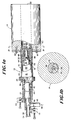
- Fig. 1a is a front elevational view of the system according to the present invention partially in section and partially fragmented to show details of construction.
- Fig. 1b is a section taken along line 1b-1b of Fig. 1a.
- Figs. 2a, 2b, 2c and 2d are fragmentary views of the front end of the burner portion of the system illustrating the means for adjusting the area of the outlet of oxidant and gas flow passages.
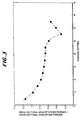
- Fig. 3 is a plot of position setting against the ratio of the cross-sectional area of the oxygen passage to the cross-sectional area of the gas passage for the burner of Fig. 1.
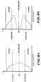
- Figs. 4a and 4b are plots of axial velocity against the position inside of the precombustor from the centerline to the interior wall of the precombustor for extreme position settings for the burner.
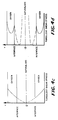
- Figs. 4c and 4d are plots of turbulent shear stress against interface position for the burner positions of Figs. 4a and 4b, respectively.
- oxy-fuel burners have been used to heat industrial furnaces with a view toward overcoming problems with conventional air-fuel burners.
- the term "oxy" or "oxygen” is taken to mean any gaseous oxidizer having more than 30% oxygen.
- oxy or oxy-fuel includes all oxidizers except air.
- fuels are taken to mean the normally gaseous fuels including, but not limited to, methane, natural gas, propane, hydrogen sulfide and the like, as well as liquid fuels, such as fuel oils, heating oils, waste oils, slurries and the like, to name but a few.
- the oxy-fuel flame adjustability in length, shape, luminosity and momentum is essential for an efficient furnace operation.
- An operator having the ability to adjust all of the foregoing conditions would have the benefit of, not only improving furnace thermal efficiency, but also increasing both quality and productivity of the furnace throughput.
- adjustability and flame gas momentum would prevent undesirable flame impingement onto the refractory of the furnace, excessive particulate entrainment by the flue, and formation of pollutants such as NOx, which often exceed the maximum Environmental Protection Agency permitted levels.
- momentum control was generally achieved by simple, but mostly impractical methods.
- the first was to use a series of replaceable fixed area nozzle tips which were changed depending upon the need for increase or decrease in momentum.
- nozzles of appropriate diameter or flow area were made to be interchangeable on the flame end of the burner.
- numeral 10 indicates the oxy-fuel burner system of the present invention.
- the oxy-fuel burner system includes an oxy-fuel burner 12 and a precombustor 14.
- the burner consists of a first housing section 16 which can be referred to as the forward housing of the burner 12.
- Section 16 has a forward end 18 referred to as the flame end of the burner 12.
- Housing 16 has a second end 20 containing a suitable threaded portion 22 proximate thereof in the form of a flange so that the second or housing portion 24 of the burner 12 can be fitted to the forward housing 16.
- Sections 16 and 24 can be mated together by use of a collar 26 which fits over a flange 28 on section 24, sealing accomplished by means of O-rings and the like (not shown) as is well known in the art.
- tubular member 30 Disposed within section 16 and concentric thereto is a tubular member 30 which is sometimes referred to as the oxygen conduit.
- Tubular member or section 30 while being generally cylindrical in shape, has a converging-diverging front section 32, the function of which will be explained hereafter.
- a fuel conduit 34 Disposed within section 30 is a fuel conduit 34 having a generally cylindrical cross-section with a forward converging-diverging nozzle shape or discharge end 36 as will hereinafter be discussed.
- gas cap, or fuel cap, or bluff body 38 Disposed within the fuel conduit 34 is a gas cap, or fuel cap, or bluff body 38 having a generally cylindrical section terminating in a forward section in the shape of a truncated cone 40.
- Sections 16, 30, 34 and 38 having generally circular cross-sections are assembled in concentric fashion along a common longitudinal axis as shown in Fig. 1b.
- Housing section 24 includes an oxygen inlet 42 which communicates as shown by arrows 44 with the passage defined between the oxygen conduit 30 and the fuel conduit 34 so that oxygen can be introduced into the burner and exit thereof through the nozzle end 18 of the burner 12.
- Burner 12 includes in housing section 24 a fuel inlet 46 which permits introduction of fuel as shown by arrows 48 into the portion of the burner between the fuel conduit 34 and the gas cap 38.
- the burner 12 is assembled, as is well known in the art, so that there is no leakage of fuel and oxygen between the various subassemblies so that the mixing of oxygen and fuel takes place at or near the flame end 18 of the burner.
- Burner 12 can include suitable adjusting mechanisms 50, 52 so that the fuel conduit 34 and gas cap 38 can be moved longitudinally within the burner 12 as well be hereinafter explained.
- Conduit 38 is fitted with a fluid-type access cap 54 so that the burner assembly can be used for firing liquid fuels.
- a precombustor 14 mounted on the forward end of the burner 12 juxtaposed to the flame end 18 is a precombustor 14.
- the precombustor 14 can be fabricated from a refractory or metal, depending on the furnace temperature, and formed to be a stand-alone unit or can be disposed inside of an outer structural shape, if required.
- the inner structure 60 of precombustor 14 is fixed to flange 56 fixed to the housing 16 of burner 12 by embedded fasteners or fasteners inserted in receiving slots 62, 64 as shown in the drawing and as is well known in the art.
- a cylindrical passage 66 which is of a diameter that will be determined in accord with the firing rate of the burner as will be explained hereinafter is formed in precombustor 14.
- the passage 66 extends for the length of the precombustor 14 to encircle and direct flame issuing from the flame end 18 of burner 12 outwardly of the discharge end 68 of the precombustor 14.
- Precombustor 14 is mounted to the wall of the furnace or vessel to be heated and can be in the shape of a refractory block used in that vessel or other shape and/or other materials on the outer surface to make it convenient for inserting into the furnace wall.
- the geometry of the precombustor 14 is a function of the firing rate as shown in U.S. Patent Application Serial No. , filed .
- the dimensions of the precombustor 14 should be such that the distance or length from the face or flame end 18 of the burner 12 to the discharge end 68 of the precombustor 14 is between 12 inches and 48 inches, the diameter of the interior cylindrical aperture or passage of the precombustor 14 should be between 2 inches and 8 inches and the ratio of length to diameter (L/d) should be between 2 and 6.
- the preferred precombustor configurations are shown in Table 1 below.
- the numbers given in the table above are empirical values derived from the measurements of flame luminosity, precombustor temperature profile, and precombustor pressure collected during experimental test firing. These dimensions go against the traditional approaches in designing burners and burner blocks since this "tight" precombustor is actually cooled and shielded by the flowing and reacting gases. As used herein "tight” refers to a small dimensional difference between the inner diameter of passage 66 of its combustor 14 and the flame produced by burner 12. In the prior art, the burner blocks were large to keep them away from the hot oxy/fuel flame which resulted in the entrainment of the furnaces gases.
- the precombustor can have a converging or diverging shape to the inner surface 66 at the discharge end 68, provided that the angle of convergence or divergence is no greater than plus or minus 15°, the angle being measured relative to the longitudinal axis of the precombustor 14.
- a burner according to the invention provides a basic flow configuration consisting of two co-flowing annular jets.
- the oxygen is discharged from the forward end of the burner 12 in the form of an annulus through the passage defined between the oxygen conduit 30 and the fuel conduit 34.
- the fuel exits the flame end 18 of the burner 12 through an annular orifice between the forward end 36 of fuel conduit 34 and the outer surface of gas cap 38.
- the two annular flow passages are created by assembly of individual conduits with the forward or tip portion of the conduits designed for minimum pressure drop for both oxygen and fuel.
- the nozzle is that portion of the oxygen conduit, fuel conduit or gas cap measured from the forward end to a point where the respective section is cylindrical in shape.
- the various flow dimensions are designed based upon experimental knowledge of fuel and oxygen, flow velocities, range of velocity adjustments needed, turbulence level, acceptable in flows, and flame characteristics of the co-flowing oxygen/fuel streams.
- the rounding of the forward end of the oxygen conduit with a suitable radius serves two important functions. The first is to facilitate a delayed and gradual mixing of fuel and oxygen streams in the precombustor 14. It has been shown that a "square-edged" (without rounded end) forward end 36 of fuel conduit 34 induces a flow separation effect. Secondly, flow separation creates a low pressure region in the shadow of the forward end 36 edge.
- the burner of Figs. 1a and 1b can be used to change the mixing rate of oxygen and fuel by moving the fuel conduit 34 relative to the oxygen conduit 30 and the fuel conduit 34 and gas cap 38 relative to each other, along an axial direction inwardly of the housing 16 of the burner 12.
- Fig. 2a shows the positioning of the oxygen conduit 30, fuel conduit 34 and gas cap 38 in what is referred to as position 13 where the gas cap 38 and the truncated cone 40 are retracted to what would be considered the far left position in the plane of the drawing and the orientation of Figs. 1a and 2b.
- Fig. 2b shows the position of the oxygen conduit 30, fuel conduit 34 and gas cap 38 to be with the flame end 18 of the burner 12.
- FIG. 2c shows what is considered to be oxygen position 1 and fuel position 13
- Fig. 2d shows oxygen position 13 and fuel position 1.
- oxygen position 1 is that position where the converging-diverging front section 32 for the oxygen conduit 30 and the fuel conduit 34 discharge end 36 are in the same plane.
- Fuel position 1 is when the discharge end 36 of fuel conduit 34 and the truncated cone 40 of gas cap 38 are in the same plane.
- position 13 for either oxygen or fuel is when the complementary parts are at the fully retracted or left-hand position as shown in the drawing.
- the retraction process for the various burner parts is done manually with the help of individual adjustment mechanisms (50, 52). By retraction one can vary the actual flow area at the flame end 18 for the fuel and oxygen.
- Fig. 3 is a plot showing the ratio of oxygen flow area to fuel flow area as a function of position settings.
- the curve shows an exponential decay from position 1 to position 10.
- the fuel flow area opens up to the maximum value whereas the oxygen flow area increases all the way to position 13 as shown in Fig. 3.
- a dip in the curve is seen at position 11 due to the foregoing reasons.
- Total axial movement of both adjusting mechanisms is approximately 1.625 in.
- the nozzles described above are designed to operate within the parameters of the precombustor 14 discussed above.
- a burner according to the present invention enables velocity variations for both a gaseous fuel such as natural gas (V ng ) and oxygen (V ox ).
- V ng natural gas
- V ox oxygen
- the position settings 1 through 13 can give high momentum to low momentum choices for flame control.
- high temperature furnace e.g. glass melters
- low velocities high position settings
- V ng and V ox should be less than 600 feet per second
- V ng /V ox should be between 0.3 and 6.0.
- lower velocities should be used with the V ng /V ox ratio being between 1.0 and 1.5.
- Oxy-fuel flame characteristics are influenced by many geometrical and fluid parameters.
- the axial velocity and turbulent shear stress profiles of both oxygen and a gaseous fuel, e.g. natural gas, at the flame end 18 are shown in Figs. 4a through 4d.
- the two extreme position settings are considered positions 1 and 13 which are used to illustrate the changes.
- the interfacial velocities and turbulent shear stress are at maximum.
- the interfacial velocities and turbulent shear stress are at minimum.
- the effects of turbulent shear stresses at the wall and fuel-oxygen interface is to introduce turbulent fluctuations (turbulent intensity) in both fuel and oxygen flows.
- Table 2 illustrates the effect of burner position settings 1 and 13 on various fluid parameters which subsequently changes the flame characteristics.
- the most influencing parameters are the turbulence intensity and mixing rates. These two parameters play an important role in changing the flame, temperature, length and its luminosity. Lower position settings (e.g., 1, 2, 3) give high momentum short flame characteristics whereas the higher position settings (e.g., 7, 8, 9) give a low momentum long flame characteristic. For example, in a partial conversion furnace with both oxy-fuel and air-fuel burners, the former would need to operate in a high momentum regime to maximize the effects of the air-fuel burners and large gas volumes on the oxy-fuel flame shape and stability. However, in a full conversion oxy-fuel furnace, low-momentum is preferable since it offers lower flame temperatures and higher flame luminosity.
- the burner of the present invention is normally subjected to a high radiation environment such as a glass melting furnace. In such a furnace the front end of the burner is normally exposed to an 2,600°F on a continuous basis. No common alloys will survive this temperature without some form of external or internal cooling.
- the burner of the present invention operates on two modes of cooling during normal operation, the first being force convective cooling by fuel and/or oxygen flowing through the burner and the second by a conduction and free convection cooling by the burner body.
- a length of at least 21 inches and approximate surface area of 230 in.2 was adequate to dissipate heat to the surroundings by conduction and free convection.
- a burner according to the present invention was adapted for oxy-oil combustion and tests run at a commercial fiberglass manufacturing facility.
- the burner of the present invention was installed into a furnace normally heated with 8 oxygen-natural gas burners.
- One of the conventional oxy-natural gas burners was replaced with the burner according to the invention which was fired using both #2 and #6 fuel oils.
- the firing rate on the burner varied between 5 and 18 gallons per hour (7 gallons produces approximately 1 million Btu) with the average of 12 gallons per hour being consumed during the test.
- the flame on the burner was found to be very luminous with the length varying from 1 to 5 feet depending upon the firing rate. Temperature of the surrounding furnace refractories increased by an average of 50°F due to the very luminous oxy-oil flame.
- Temperature of the precombustor was found to be similar to the furnace temperature even though the flame had been very intense inside the precombustor. Lastly, the inspection of the burner assembly at the end of the test revealed no deposition or metal discoloration due to the high temperature of the glass melting furnace or combustion process.
Landscapes
- Engineering & Computer Science (AREA)
- Chemical & Material Sciences (AREA)
- Combustion & Propulsion (AREA)
- Materials Engineering (AREA)
- Organic Chemistry (AREA)
- Mechanical Engineering (AREA)
- General Engineering & Computer Science (AREA)
- Manufacturing & Machinery (AREA)
- Metallurgy (AREA)
- Pre-Mixing And Non-Premixing Gas Burner (AREA)
- Gas Burners (AREA)
Applications Claiming Priority (2)
| Application Number | Priority Date | Filing Date | Title |
|---|---|---|---|
| US860651 | 1986-05-07 | ||
| US07/860,651 US5199866A (en) | 1992-03-30 | 1992-03-30 | Adjustable momentum self-cooled oxy/fuel burner for heating in high temperature environments |
Publications (2)
| Publication Number | Publication Date |
|---|---|
| EP0563793A2 true EP0563793A2 (de) | 1993-10-06 |
| EP0563793A3 EP0563793A3 (en) | 1993-12-08 |
Family
ID=25333698
Family Applications (1)
| Application Number | Title | Priority Date | Filing Date |
|---|---|---|---|
| EP19930104941 Withdrawn EP0563793A3 (en) | 1992-03-30 | 1993-03-25 | Adjustable momentum self-cooled oxy/fuel burner for heating in high-temperature environments |
Country Status (8)
| Country | Link |
|---|---|
| US (1) | US5199866A (de) |
| EP (1) | EP0563793A3 (de) |
| JP (1) | JP2588355B2 (de) |
| KR (1) | KR970009481B1 (de) |
| CA (1) | CA2092252C (de) |
| CZ (1) | CZ279820B6 (de) |
| MY (1) | MY108788A (de) |
| PL (1) | PL172304B1 (de) |
Cited By (8)
| Publication number | Priority date | Publication date | Assignee | Title |
|---|---|---|---|---|
| WO1998020282A1 (en) * | 1996-11-01 | 1998-05-14 | Hydrogen Burner Technology, Inc. | Dynamic fluid injector |
| EP1138638A3 (de) * | 2000-03-29 | 2002-01-02 | The Boc Group, Inc. | Brenner und Verbrennungsverfahren |
| EP1627855A3 (de) * | 2004-08-16 | 2006-03-15 | Air Products And Chemicals, Inc. | Brenner und Verfahren zum Verbrennen von Brennstoffen |
| WO2007048429A1 (en) * | 2005-10-28 | 2007-05-03 | L'Air Liquide Société Anonyme pour l'Etude et l'Exploitation des Procédés Georges Claude | Oxygen/fuel burner with variable flame length |
| EP2143999A1 (de) | 2008-07-08 | 2010-01-13 | L'Air Liquide Société Anonyme pour l'Etude et l'Exploitation des Procédés Georges Claude | Brennerbaugruppe und Verbrennungsverfahren |
| CN102405375A (zh) * | 2009-02-24 | 2012-04-04 | 艾森曼股份公司 | 热力后燃烧装置的燃烧器 |
| DE102004037620C5 (de) * | 2004-08-02 | 2015-09-17 | Air Liquide Deutschland Gmbh | Brennstoff-Sauerstoff-Brenner mit variabler Flammenlänge |
| DE102015220305A1 (de) | 2015-10-19 | 2017-04-20 | Sms Group Gmbh | Brenner |
Families Citing this family (105)
| Publication number | Priority date | Publication date | Assignee | Title |
|---|---|---|---|---|
| US5547368A (en) * | 1993-03-01 | 1996-08-20 | Air Products And Chemicals, Inc. | Process and device for combustion-enhanced atomization and vaporization of liquid fuels |
| US5449286A (en) * | 1993-06-22 | 1995-09-12 | Praxair Technology, Inc. | Controlled flame fuel jet combustion |
| US5405082A (en) * | 1993-07-06 | 1995-04-11 | Corning Incorporated | Oxy/fuel burner with low volume fuel stream projection |
| US5439373A (en) * | 1993-09-13 | 1995-08-08 | Praxair Technology, Inc. | Luminous combustion system |
| US5490775A (en) * | 1993-11-08 | 1996-02-13 | Combustion Tec, Inc. | Forward injection oxy-fuel burner |
| ES2142969T3 (es) * | 1994-05-18 | 2000-05-01 | Praxair Technology Inc | Metodo de funcionamiento de un horno. |
| US5551867A (en) * | 1994-10-07 | 1996-09-03 | Schuller International, Inc. | Method of converting a furnace to oxygen-fuel while it is operating and aburner block assembly |
| US5575637A (en) * | 1994-11-04 | 1996-11-19 | Air Products And Chemicals, Inc. | Method and device for low-NOx high efficiency heating in high temperature furnaces |
| US5597298A (en) * | 1994-12-13 | 1997-01-28 | Praxair Technology, Inc. | Laminar flow burner |
| US5725367A (en) * | 1994-12-30 | 1998-03-10 | Combustion Tec, Inc. | Method and apparatus for dispersing fuel and oxidant from a burner |
| US5567141A (en) * | 1994-12-30 | 1996-10-22 | Combustion Tec, Inc. | Oxy-liquid fuel combustion process and apparatus |
| US5545031A (en) * | 1994-12-30 | 1996-08-13 | Combustion Tec, Inc. | Method and apparatus for injecting fuel and oxidant into a combustion burner |
| US5611682A (en) * | 1995-09-05 | 1997-03-18 | Air Products And Chemicals, Inc. | Low-NOx staged combustion device for controlled radiative heating in high temperature furnaces |
| AT402963B (de) * | 1995-09-07 | 1997-10-27 | Voest Alpine Ind Anlagen | Verfahren zum verbrennen von brennstoff |
| US5743723A (en) * | 1995-09-15 | 1998-04-28 | American Air Liquide, Inc. | Oxy-fuel burner having coaxial fuel and oxidant outlets |
| US5904477A (en) * | 1995-10-05 | 1999-05-18 | Shell Oil Company | Burner for partial oxidation of a hydrocarbon-containing fuel |
| US5814121A (en) * | 1996-02-08 | 1998-09-29 | The Boc Group, Inc. | Oxygen-gas fuel burner and glass forehearth containing the oxygen-gas fuel burner |
| US6253578B1 (en) * | 1996-04-12 | 2001-07-03 | Praxair Technology, Inc. | Glass melting process and apparatus with reduced emissions and refractory corrosion |
| EP0819888B1 (de) * | 1996-07-17 | 2001-09-26 | Johns Manville International, Inc. | Verfahren zum Umwandeln eines Ofens von Luft-Brenner in Sauerstoff-Brenner und Brennerstein |
| US6029910A (en) | 1998-02-05 | 2000-02-29 | American Air Liquide, Inc. | Low firing rate oxy-fuel burner |
| FR2774745B1 (fr) * | 1998-02-10 | 2000-03-17 | Air Liquide | Procede de chauffage de produits dans une enceinte et bruleur pour la mise en oeuvre de ce procede |
| FR2786555B1 (fr) | 1998-11-30 | 2001-01-19 | Air Liquide | Systeme de combustion a combustible liquide |
| US6233974B1 (en) * | 1999-01-25 | 2001-05-22 | Combustion Tec | Oxygen-gaseous forehearth burner for air-fuel and oxy-fuel forehearth burner block geometries |
| US6220852B1 (en) * | 1999-03-25 | 2001-04-24 | Hauck Manufacturing Company | Variable exit high velocity burner |
| US6176702B1 (en) * | 1999-04-07 | 2001-01-23 | Combustion Tec | Simple remotely tuned solid core fuel jet, low NOx fuel gas burner |
| US6126438A (en) | 1999-06-23 | 2000-10-03 | American Air Liquide | Preheated fuel and oxidant combustion burner |
| US6155818A (en) * | 1999-12-16 | 2000-12-05 | L'air Liquide, Societe Anonyme Pour L'etude Et, L'exploitation Des Procedes, Georges Claude | Oxy-burner having a back-up firing system and method of operation |
| US6659762B2 (en) | 2001-09-17 | 2003-12-09 | L'air Liquide - Societe Anonyme A' Directoire Et Conseil De Surveillance Pour L'etude Et L'exploitation Des Procedes Georges Claude | Oxygen-fuel burner with adjustable flame characteristics |
| US6582218B1 (en) * | 2002-06-11 | 2003-06-24 | Air Products And Chemicals, Inc. | Self-cooling oxy-fuel through-port burner for protruding into glass furnace atmosphere |
| FR2854943B1 (fr) * | 2003-05-13 | 2006-05-26 | Air Liquide | Procede de controle de bruleurs assurant le chauffage de canaux d'ecoulement de verre liquide |
| US6866504B2 (en) * | 2003-08-01 | 2005-03-15 | Mg Industries | Burner with high-efficiency atomization |
| DE10349075B4 (de) * | 2003-10-22 | 2016-01-07 | Airbus Operations Gmbh | Vorrichtung zur Zufuhr von Brennstoff zu einem Brenner in einem Brennstoffzellensystem mit einem Reformer |
| SE528808C2 (sv) * | 2004-09-15 | 2007-02-20 | Aga Ab | Förfarande vid förbränning, jämte brännare |
| US20070221142A1 (en) * | 2006-03-20 | 2007-09-27 | American Water Heater Company, A Corporation Of The State Of Nevada | Ultra low NOx water heater |
| US20070218776A1 (en) * | 2006-03-20 | 2007-09-20 | American Water Heater Company, A Corporation Of The State Of Nevade | Fuel supply line connector for water heater mounting bracket |
| US20080096146A1 (en) * | 2006-10-24 | 2008-04-24 | Xianming Jimmy Li | Low NOx staged fuel injection burner for creating plug flow |
| KR100805630B1 (ko) * | 2006-12-01 | 2008-02-20 | 주식회사 경동나비엔 | 가스보일러의 연소장치 |
| HRP20170208T4 (hr) | 2007-02-02 | 2019-12-27 | Messer Austria Gmbh | Gorionik |
| US8454354B2 (en) * | 2008-05-08 | 2013-06-04 | Air Products And Chemicals, Inc. | Highly radiative burner and combustion process |
| US8105074B2 (en) * | 2008-06-30 | 2012-01-31 | Praxair Technology, Inc. | Reliable ignition of hot oxygen generator |
| EP2326878A2 (de) * | 2008-09-26 | 2011-06-01 | Air Products and Chemicals, Inc. | Verbrennungssystem mit vorbrennkammer mit rückgeführtem rauchgas |
| FR2941286B1 (fr) * | 2009-01-16 | 2012-08-31 | Air Liquide | Bruleur pilote air-gaz pouvant fonctionner a l'oxygene. |
| JP5132603B2 (ja) * | 2009-02-18 | 2013-01-30 | 日本碍子株式会社 | 長炎lngバーナー |
| US8104695B2 (en) * | 2009-03-18 | 2012-01-31 | General Electric Company | Fuel injector gassifer nozzle having adjustable annulus |
| US8172566B2 (en) | 2010-02-18 | 2012-05-08 | Air Products And Chemicals, Inc. | Liquid fuel combustion process and apparatus |
| US9032760B2 (en) | 2012-07-03 | 2015-05-19 | Johns Manville | Process of using a submerged combustion melter to produce hollow glass fiber or solid glass fiber having entrained bubbles, and burners and systems to make such fibers |
| US10322960B2 (en) | 2010-06-17 | 2019-06-18 | Johns Manville | Controlling foam in apparatus downstream of a melter by adjustment of alkali oxide content in the melter |
| US8875544B2 (en) | 2011-10-07 | 2014-11-04 | Johns Manville | Burner apparatus, submerged combustion melters including the burner, and methods of use |
| US8973405B2 (en) | 2010-06-17 | 2015-03-10 | Johns Manville | Apparatus, systems and methods for reducing foaming downstream of a submerged combustion melter producing molten glass |
| US9021838B2 (en) | 2010-06-17 | 2015-05-05 | Johns Manville | Systems and methods for glass manufacturing |
| US8707739B2 (en) | 2012-06-11 | 2014-04-29 | Johns Manville | Apparatus, systems and methods for conditioning molten glass |
| US9096452B2 (en) | 2010-06-17 | 2015-08-04 | Johns Manville | Methods and systems for destabilizing foam in equipment downstream of a submerged combustion melter |
| US8973400B2 (en) | 2010-06-17 | 2015-03-10 | Johns Manville | Methods of using a submerged combustion melter to produce glass products |
| US8650914B2 (en) | 2010-09-23 | 2014-02-18 | Johns Manville | Methods and apparatus for recycling glass products using submerged combustion |
| US8991215B2 (en) | 2010-06-17 | 2015-03-31 | Johns Manville | Methods and systems for controlling bubble size and bubble decay rate in foamed glass produced by a submerged combustion melter |
| US8769992B2 (en) | 2010-06-17 | 2014-07-08 | Johns Manville | Panel-cooled submerged combustion melter geometry and methods of making molten glass |
| US8997525B2 (en) | 2010-06-17 | 2015-04-07 | Johns Manville | Systems and methods for making foamed glass using submerged combustion |
| US9776903B2 (en) | 2010-06-17 | 2017-10-03 | Johns Manville | Apparatus, systems and methods for processing molten glass |
| US8707740B2 (en) | 2011-10-07 | 2014-04-29 | Johns Manville | Submerged combustion glass manufacturing systems and methods |
| KR101015561B1 (ko) * | 2010-08-13 | 2011-02-16 | 김병두 | 용사 코팅을 위한 2중 노즐 캡 |
| JP2012102911A (ja) * | 2010-11-08 | 2012-05-31 | Air Liquide Japan Ltd | 燃焼バーナ |
| CN103782099B (zh) | 2011-02-16 | 2016-03-16 | 气体产品与化学公司 | 预混合空气-气体喷燃器的氧富化 |
| JP2012193918A (ja) * | 2011-03-17 | 2012-10-11 | Taiyo Nippon Sanso Corp | 無機質球状化粒子製造用バーナ、無機質球状化粒子製造装置、及び無機質球状化粒子の製造方法 |
| US9533905B2 (en) | 2012-10-03 | 2017-01-03 | Johns Manville | Submerged combustion melters having an extended treatment zone and methods of producing molten glass |
| JP6029857B2 (ja) * | 2012-05-23 | 2016-11-24 | 株式会社パロマ | 濃淡バーナ |
| US20140000297A1 (en) * | 2012-06-29 | 2014-01-02 | Air Liquide Industrial U.S. L.P. | Production of Particles from Liquids or Suspensions with Liquid Cryogens |
| WO2014055199A1 (en) | 2012-10-03 | 2014-04-10 | Johns Manville | Methods and systems for destabilizing foam in equipment downstream of a submerged combustion melter |
| US20140141382A1 (en) * | 2012-11-19 | 2014-05-22 | Neil Simpson | Oxygen injector for furnace and regenerator |
| US9227865B2 (en) | 2012-11-29 | 2016-01-05 | Johns Manville | Methods and systems for making well-fined glass using submerged combustion |
| PL2999923T3 (pl) | 2013-05-22 | 2019-02-28 | Johns Manville | Piec do topienia ze spalaniem pod powierzchnią cieczy z udoskonalonym palnikiem oraz odpowiadający sposób |
| WO2014189501A1 (en) | 2013-05-22 | 2014-11-27 | Johns Manville | Submerged combustion burners, melters, and methods of use |
| US10138151B2 (en) | 2013-05-22 | 2018-11-27 | Johns Manville | Submerged combustion burners and melters, and methods of use |
| WO2014189499A1 (en) | 2013-05-22 | 2014-11-27 | Johns Manville | Submerged combustion burners and melters, and methods of use |
| WO2014189504A1 (en) | 2013-05-22 | 2014-11-27 | Johns Manville | Submerged combustion burners |
| US10183884B2 (en) | 2013-05-30 | 2019-01-22 | Johns Manville | Submerged combustion burners, submerged combustion glass melters including the burners, and methods of use |
| WO2014193388A1 (en) | 2013-05-30 | 2014-12-04 | Johns Manville | Submerged combustion glass melting systems and methods of use |
| AT513618B1 (de) * | 2013-07-02 | 2014-06-15 | Cotraco Holding Gmbh | Lanze für die Verbrennung oder Abfackelung von brennbaren Abgasen |
| US10858278B2 (en) | 2013-07-18 | 2020-12-08 | Johns Manville | Combustion burner |
| FR3018900B1 (fr) * | 2014-03-19 | 2016-04-15 | Yahtec | Dispositif de bruleur a pre melange gaz |
| EP3180567B1 (de) * | 2014-08-15 | 2020-11-25 | Eclipse Inc. | Brenner mit doppeltem auslass und verfahren |
| EP3078908A1 (de) | 2015-04-08 | 2016-10-12 | Linde Aktiengesellschaft | Brennervorrichtung und verfahren |
| CN105066129B (zh) * | 2015-07-27 | 2017-04-12 | 河北中北环保科技有限公司 | 一种动量可调节的纯氧烧嘴 |
| US9751792B2 (en) | 2015-08-12 | 2017-09-05 | Johns Manville | Post-manufacturing processes for submerged combustion burner |
| US10670261B2 (en) | 2015-08-27 | 2020-06-02 | Johns Manville | Burner panels, submerged combustion melters, and methods |
| US10041666B2 (en) | 2015-08-27 | 2018-08-07 | Johns Manville | Burner panels including dry-tip burners, submerged combustion melters, and methods |
| US9815726B2 (en) | 2015-09-03 | 2017-11-14 | Johns Manville | Apparatus, systems, and methods for pre-heating feedstock to a melter using melter exhaust |
| US9982884B2 (en) | 2015-09-15 | 2018-05-29 | Johns Manville | Methods of melting feedstock using a submerged combustion melter |
| US10837705B2 (en) | 2015-09-16 | 2020-11-17 | Johns Manville | Change-out system for submerged combustion melting burner |
| US10081563B2 (en) | 2015-09-23 | 2018-09-25 | Johns Manville | Systems and methods for mechanically binding loose scrap |
| US10144666B2 (en) | 2015-10-20 | 2018-12-04 | Johns Manville | Processing organics and inorganics in a submerged combustion melter |
| KR101687666B1 (ko) * | 2016-03-23 | 2016-12-19 | 국방과학연구소 | 예연소기형 촉매점화기 및 이를 적용한 연소기 |
| US10246362B2 (en) | 2016-06-22 | 2019-04-02 | Johns Manville | Effective discharge of exhaust from submerged combustion melters and methods |
| US10301208B2 (en) | 2016-08-25 | 2019-05-28 | Johns Manville | Continuous flow submerged combustion melter cooling wall panels, submerged combustion melters, and methods of using same |
| US10337732B2 (en) * | 2016-08-25 | 2019-07-02 | Johns Manville | Consumable tip burners, submerged combustion melters including same, and methods |
| US10196294B2 (en) | 2016-09-07 | 2019-02-05 | Johns Manville | Submerged combustion melters, wall structures or panels of same, and methods of using same |
| US10233105B2 (en) | 2016-10-14 | 2019-03-19 | Johns Manville | Submerged combustion melters and methods of feeding particulate material into such melters |
| CN109114559A (zh) * | 2017-06-22 | 2019-01-01 | 昆山庚天热能科技有限公司 | 一种燃烧器空气燃气预混自动控制方法 |
| US10513453B2 (en) * | 2017-07-28 | 2019-12-24 | Air Products And Chemicals, Inc. | Oxygen-fuel burner for a glass melting furnace |
| JP6993844B2 (ja) * | 2017-11-01 | 2022-01-14 | 日鉄テクノロジー株式会社 | 溶融金属容器の付着物除去装置及び付着物除去方法 |
| FR3074262B1 (fr) * | 2017-11-30 | 2020-12-11 | Saint Gobain Isover | Bruleur comprenant une piece d'usure |
| CN108361690B (zh) * | 2018-01-29 | 2020-01-10 | 西安交通大学 | 一种带远程燃尽风的防结渣型低NOx燃烧器 |
| KR101978864B1 (ko) * | 2018-08-20 | 2019-05-15 | 한국중부발전(주) | 내부 화염 분사형 터보 점화장치 |
| WO2020131113A1 (en) | 2018-12-21 | 2020-06-25 | Selas Heat Technology Company Llc | Oxy forehearth burner assembly |
| US12359807B2 (en) | 2019-12-20 | 2025-07-15 | Jupiter Oxygen Corporation | Combustion system comprising an annular shroud burner |
| US10845052B1 (en) | 2019-12-20 | 2020-11-24 | Jupiter Oxygen Corporation | Combustion system comprising an annular shroud burner |
Family Cites Families (10)
| Publication number | Priority date | Publication date | Assignee | Title |
|---|---|---|---|---|
| DE384760C (de) * | 1923-11-05 | Nicola Lengersdorff | Brenner zur Ausuebung des Verfahrens zum Beheizen von Kanaloefen | |
| US368266A (en) * | 1887-08-16 | weight | ||
| FR368208A (fr) * | 1906-07-19 | 1906-11-22 | Conrad Krug | Four de verrerie |
| US1779647A (en) * | 1927-11-23 | 1930-10-28 | Int Comb Eng Corp | Burner |
| US4541796A (en) * | 1980-04-10 | 1985-09-17 | Union Carbide Corporation | Oxygen aspirator burner for firing a furnace |
| US4378205A (en) * | 1980-04-10 | 1983-03-29 | Union Carbide Corporation | Oxygen aspirator burner and process for firing a furnace |
| DE3306892A1 (de) * | 1983-02-26 | 1984-08-30 | Jörg 8775 Partenstein Köster | Gasbrenner zur beheizung von industrieoefen |
| WO1986007436A1 (en) * | 1985-06-03 | 1986-12-18 | Asarco Incorporated | Gas burner |
| CN1007920B (zh) * | 1985-07-15 | 1990-05-09 | 美国氧化公司 | 烃类流体燃料燃烧、控制方法及装置 |
| US4690635A (en) * | 1986-07-21 | 1987-09-01 | Maxon Corporation | High temperature burner assembly |
-
1992
- 1992-03-30 US US07/860,651 patent/US5199866A/en not_active Expired - Fee Related
-
1993
- 1993-03-23 CA CA002092252A patent/CA2092252C/en not_active Expired - Fee Related
- 1993-03-23 MY MYPI93000513A patent/MY108788A/en unknown
- 1993-03-24 CZ CZ93492A patent/CZ279820B6/cs unknown
- 1993-03-25 KR KR93004663A patent/KR970009481B1/ko not_active Expired - Lifetime
- 1993-03-25 EP EP19930104941 patent/EP0563793A3/en not_active Withdrawn
- 1993-03-26 JP JP5091957A patent/JP2588355B2/ja not_active Expired - Lifetime
- 1993-03-30 PL PL93298304A patent/PL172304B1/pl unknown
Cited By (15)
| Publication number | Priority date | Publication date | Assignee | Title |
|---|---|---|---|---|
| WO1998020282A1 (en) * | 1996-11-01 | 1998-05-14 | Hydrogen Burner Technology, Inc. | Dynamic fluid injector |
| US5944510A (en) * | 1996-11-01 | 1999-08-31 | Greiner; Leonard | Dynamic fluid injector |
| EP1138638A3 (de) * | 2000-03-29 | 2002-01-02 | The Boc Group, Inc. | Brenner und Verbrennungsverfahren |
| US6474982B2 (en) | 2000-03-29 | 2002-11-05 | The Boc Group, Inc. | Burner and combustion method for heating surfaces susceptible to oxidation or reduction |
| DE102004037620C5 (de) * | 2004-08-02 | 2015-09-17 | Air Liquide Deutschland Gmbh | Brennstoff-Sauerstoff-Brenner mit variabler Flammenlänge |
| US7390189B2 (en) | 2004-08-16 | 2008-06-24 | Air Products And Chemicals, Inc. | Burner and method for combusting fuels |
| US8512033B2 (en) | 2004-08-16 | 2013-08-20 | Air Products And Chemicals, Inc. | Fuel nozzle for reducing carbon build up |
| EP1627855A3 (de) * | 2004-08-16 | 2006-03-15 | Air Products And Chemicals, Inc. | Brenner und Verfahren zum Verbrennen von Brennstoffen |
| WO2007048429A1 (en) * | 2005-10-28 | 2007-05-03 | L'Air Liquide Société Anonyme pour l'Etude et l'Exploitation des Procédés Georges Claude | Oxygen/fuel burner with variable flame length |
| EP2143999A1 (de) | 2008-07-08 | 2010-01-13 | L'Air Liquide Société Anonyme pour l'Etude et l'Exploitation des Procédés Georges Claude | Brennerbaugruppe und Verbrennungsverfahren |
| WO2010003866A1 (en) * | 2008-07-08 | 2010-01-14 | L'air Liquide Societe Anonyme Pour L'etude Et L'exploitation Des Procedes Georges Claude | Burner assembly and method of combustion |
| CN102089587B (zh) * | 2008-07-08 | 2013-05-01 | 乔治洛德方法研究和开发液化空气有限公司 | 燃烧器组件和燃烧方法 |
| CN102405375A (zh) * | 2009-02-24 | 2012-04-04 | 艾森曼股份公司 | 热力后燃烧装置的燃烧器 |
| CN102405375B (zh) * | 2009-02-24 | 2015-01-28 | 艾森曼股份公司 | 热力后燃烧装置的燃烧器 |
| DE102015220305A1 (de) | 2015-10-19 | 2017-04-20 | Sms Group Gmbh | Brenner |
Also Published As
| Publication number | Publication date |
|---|---|
| JP2588355B2 (ja) | 1997-03-05 |
| EP0563793A3 (en) | 1993-12-08 |
| CA2092252A1 (en) | 1993-10-01 |
| US5199866A (en) | 1993-04-06 |
| CA2092252C (en) | 1996-07-16 |
| CZ49293A3 (en) | 1994-03-16 |
| MY108788A (en) | 1996-11-30 |
| PL172304B1 (pl) | 1997-09-30 |
| KR930020076A (ko) | 1993-10-19 |
| CZ279820B6 (cs) | 1995-07-12 |
| JPH06101820A (ja) | 1994-04-12 |
| PL298304A1 (en) | 1993-12-13 |
| KR970009481B1 (en) | 1997-06-13 |
Similar Documents
| Publication | Publication Date | Title |
|---|---|---|
| US5199866A (en) | Adjustable momentum self-cooled oxy/fuel burner for heating in high temperature environments | |
| US5346390A (en) | Method and apparatus for oxy-fuel heating with lowered NOx in high temperature corrosive environments | |
| US5490775A (en) | Forward injection oxy-fuel burner | |
| US4378205A (en) | Oxygen aspirator burner and process for firing a furnace | |
| US4541796A (en) | Oxygen aspirator burner for firing a furnace | |
| RU2426030C2 (ru) | УЗЕЛ ГОРЕЛОК С УЛЬТРАНИЗКОЙ ЭМИССИЕЙ NOx | |
| US4986748A (en) | Wide range oxy-fuel burner and furnace operation | |
| US5299929A (en) | Fuel burner apparatus and method employing divergent flow nozzle | |
| US5743723A (en) | Oxy-fuel burner having coaxial fuel and oxidant outlets | |
| EP0877203B1 (de) | Verbrennungsverfahren mit zweifacher Oxidationsmitteleinfuhr | |
| RU2394186C2 (ru) | Горелка для сжигания топлива (варианты), способ сжигания топлива с окислителем (варианты) и способ плавки стекла | |
| US6910879B2 (en) | Combustion method comprising separate injections of fuel and oxidant and burner assembly therefor | |
| KR20010040674A (ko) | 저연소비의 산소-연료 버너 | |
| US3638932A (en) | Combined burner-lance for fume suppression in molten metals | |
| EP0633228B1 (de) | Verfahren zur Glasherstellung mit Oxy-Fuel-Feuerung im Speisekanal | |
| US4304549A (en) | Recuperator burner for industrial furnaces | |
| US5180302A (en) | Radiant gas burner and method | |
| US5458483A (en) | Oxygen-fuel burner with integral staged oxygen supply | |
| EP0614044A2 (de) | Verfahren und Vorrichtung zur mit durch Verbrennung verbesserten Zerstäubung und Verdampfung von flüssigen Brennstoffen | |
| US3387784A (en) | Burner for fluid fuels | |
| CA1100029A (en) | Premix gas burner assembly for copper melting furnace | |
| CN110073145B (zh) | 具有火焰稳定性的流体燃烧器 | |
| DE59010544D1 (de) | Brennerkopf für die vormischartige Verbrennung eines flüssigen Brennstoffes in einer atmosphärischen Feuerungsanlage | |
| SK61893A3 (sk) | Spaľovací systém na kyslík a palivo | |
| SU894300A1 (ru) | Балочна многосоплова горелка шахтной печи |
Legal Events
| Date | Code | Title | Description |
|---|---|---|---|
| PUAI | Public reference made under article 153(3) epc to a published international application that has entered the european phase |
Free format text: ORIGINAL CODE: 0009012 |
|
| AK | Designated contracting states |
Kind code of ref document: A2 Designated state(s): BE CH DE ES FR GB IT LI NL SE |
|
| PUAL | Search report despatched |
Free format text: ORIGINAL CODE: 0009013 |
|
| AK | Designated contracting states |
Kind code of ref document: A3 Designated state(s): BE CH DE ES FR GB IT LI NL SE |
|
| 17P | Request for examination filed |
Effective date: 19940316 |
|
| 17Q | First examination report despatched |
Effective date: 19950906 |
|
| 18D | Application deemed to be withdrawn |
Effective date: 19971129 |