EP0563885A2 - Appareil de direction de roues arrières pour véhicules - Google Patents
Appareil de direction de roues arrières pour véhicules Download PDFInfo
- Publication number
- EP0563885A2 EP0563885A2 EP93105256A EP93105256A EP0563885A2 EP 0563885 A2 EP0563885 A2 EP 0563885A2 EP 93105256 A EP93105256 A EP 93105256A EP 93105256 A EP93105256 A EP 93105256A EP 0563885 A2 EP0563885 A2 EP 0563885A2
- Authority
- EP
- European Patent Office
- Prior art keywords
- yaw rate
- steering
- angle
- steering angle
- vehicle speed
- Prior art date
- Legal status (The legal status is an assumption and is not a legal conclusion. Google has not performed a legal analysis and makes no representation as to the accuracy of the status listed.)
- Granted
Links
Images


Classifications
-
- G—PHYSICS
- G01—MEASURING; TESTING
- G01P—MEASURING LINEAR OR ANGULAR SPEED, ACCELERATION, DECELERATION, OR SHOCK; INDICATING PRESENCE, ABSENCE, OR DIRECTION, OF MOVEMENT
- G01P21/00—Testing or calibrating of apparatus or devices covered by the preceding groups
- G01P21/02—Testing or calibrating of apparatus or devices covered by the preceding groups of speedometers
-
- B—PERFORMING OPERATIONS; TRANSPORTING
- B62—LAND VEHICLES FOR TRAVELLING OTHERWISE THAN ON RAILS
- B62D—MOTOR VEHICLES; TRAILERS
- B62D7/00—Steering linkage; Stub axles or their mountings
- B62D7/06—Steering linkage; Stub axles or their mountings for individually-pivoted wheels, e.g. on king-pins
- B62D7/14—Steering linkage; Stub axles or their mountings for individually-pivoted wheels, e.g. on king-pins the pivotal axes being situated in more than one plane transverse to the longitudinal centre line of the vehicle, e.g. all-wheel steering
-
- B—PERFORMING OPERATIONS; TRANSPORTING
- B60—VEHICLES IN GENERAL
- B60G—VEHICLE SUSPENSION ARRANGEMENTS
- B60G17/00—Resilient suspensions having means for adjusting the spring or vibration-damper characteristics, for regulating the distance between a supporting surface and a sprung part of vehicle or for locking suspension during use to meet varying vehicular or surface conditions, e.g. due to speed or load
- B60G17/015—Resilient suspensions having means for adjusting the spring or vibration-damper characteristics, for regulating the distance between a supporting surface and a sprung part of vehicle or for locking suspension during use to meet varying vehicular or surface conditions, e.g. due to speed or load the regulating means comprising electric or electronic elements
- B60G17/0195—Resilient suspensions having means for adjusting the spring or vibration-damper characteristics, for regulating the distance between a supporting surface and a sprung part of vehicle or for locking suspension during use to meet varying vehicular or surface conditions, e.g. due to speed or load the regulating means comprising electric or electronic elements characterised by the regulation being combined with other vehicle control systems
-
- B—PERFORMING OPERATIONS; TRANSPORTING
- B62—LAND VEHICLES FOR TRAVELLING OTHERWISE THAN ON RAILS
- B62D—MOTOR VEHICLES; TRAILERS
- B62D7/00—Steering linkage; Stub axles or their mountings
- B62D7/06—Steering linkage; Stub axles or their mountings for individually-pivoted wheels, e.g. on king-pins
- B62D7/14—Steering linkage; Stub axles or their mountings for individually-pivoted wheels, e.g. on king-pins the pivotal axes being situated in more than one plane transverse to the longitudinal centre line of the vehicle, e.g. all-wheel steering
- B62D7/15—Steering linkage; Stub axles or their mountings for individually-pivoted wheels, e.g. on king-pins the pivotal axes being situated in more than one plane transverse to the longitudinal centre line of the vehicle, e.g. all-wheel steering characterised by means varying the ratio between the steering angles of the steered wheels
- B62D7/159—Steering linkage; Stub axles or their mountings for individually-pivoted wheels, e.g. on king-pins the pivotal axes being situated in more than one plane transverse to the longitudinal centre line of the vehicle, e.g. all-wheel steering characterised by means varying the ratio between the steering angles of the steered wheels characterised by computing methods or stabilisation processes or systems, e.g. responding to yaw rate, lateral wind, load, road condition
Definitions
- the present invention relates to a rear-wheel steering apparatus capable of detecting a change rate of revolved angle of a vehicle (hereinafter referred to as a "yaw rate signal") on a level surface and controlling the steering angle of the rear wheels based on the detected yaw rate signal. More particularly, it relates to calibration of the yaw rate sensor which detects a yaw rate signal.
- a rear-wheel steering apparatus of "yaw rate feedback control” has been proposed in order to secure directional stability of vehicle.
- the disclosed apparatus is capable of detecting a yaw rate signal of the vehicle, and turning the rear wheels to a phase which is opposite to that of front wheels immediately after the control of the front wheels has started, and then to an in-phase side in accordance with occurrence of the yaw rate signal.
- Front (head) rotatability and direction stability of vehicle body are balanced by this control.
- Fig. 1 shows the characteristics of change in a steering ratio ⁇ S when the vehicle body is turned by the yaw rate type rear-wheel steering apparatus. As shown in Fig. 1, the steering-angle ratio appears in the opposite phase at beginning. The steering-angle ratio then swings to the in-phase. Since this change brings considerable effect to the movement of the vehicle, it is desirable that a yaw rate is detected accurately.
- the yaw rate sensor deals with a signal representing a change rate of the yaw rate signal, it is difficult to set a reference position physically. Furthermore, in a general yaw rate sensor, the original point drifts, therefore, calibration is often required.
- the speed "zero" may be outputted even when the actual vehicle speed is 2 km/h (that is, the vehicle is travelling at approximately 2 km/h).
- calibration of the yaw rate sensor is performed when the speed sensor indicates "zero", even if the actual vehicle speed is not "zero" and yaw rate signals have been generated, the calibration is performed with the sensor output at that time as an original point of the yaw rate signal.
- a rear-wheel steering apparatus which controls to correct a steering angle of the rear wheels by inputting a yaw rate signal as a parameter, comprising: a yaw rate sensor for detecting a yaw rate signal; speed detection means for detecting a vehicle speed; steering-angle detection means for detecting a steering angle; and calibration means for calibrating the yaw rate sensor in a case where the vehicle speed detected by the vehicle speed detection means is substantially zero and the steering angle detected by the steering-angle detection means is less than a predetermined value.
- Fig. 2 illustrates the construction of the four-wheel steering system of the present embodiment.
- the rear-wheel steering apparatus 10 comprises a rear-wheel steering mechanism 18, steering-angle-ratio adjusting mechanism 20 for setting and adjusting a steering-angle ratio ⁇ S , and control unit 22 for controlling the steering-angle-ratio adjusting mechanism 20.
- the rear-wheel steering mechanism 18 is functionally connected to a front-wheel steering mechanism 14 for steering front wheels 12 through a transfer shaft 52 and controls rear wheels 16 so that an angle becomes a predetermined target steering angle in accordance with the steering angle of the front-wheel steering angle ⁇ F which is inputted from the front-wheel steering mechanism 14.
- the steering-angle-ratio adjusting mechanism 20 is provided in the rear-wheel steering mechanism 18, and sets and adjusts the steering-angle ratio ⁇ S which is expressed as a ratio of the rear-wheel steering angle ⁇ R with respect to the front-wheel steering angle ⁇ F .
- the control unit 22 inputs signals of a vehicle speed V from a speed sensor 24, front-wheel steering angle ⁇ F from a front-wheel steering sensor 26 (provided on the steering shaft), steering-angle-ratio ⁇ S from a steering-angle-ratio sensor 28, and yaw rate signal ⁇ from a yaw rate sensor 25.
- the source of supply for an oil pressure is a pump 29 of Fig. 2.
- the pump 29 transfers oil stored in an oil tank 19 to a hydraulic release circuit 31 through a pipe 90.
- the release circuit 31 is a circuit to let oil pressure out of the steering mechanism 18 so that the rear wheels are forced to return to the neutral position in case of a failure.
- Numeral 91 is a return pipe from the steering mechanism 18.
- the steering-angle-ratio adjusting mechanism 20 is controlled in accordance with so-called "phase inversion" control of the control unit 22 so that the steering-angle-ratio ⁇ S becomes negative immediately after the front wheels are steered and it changes to positive later, when the front wheels are turned from the steering angle 0 o in the intermediate speed and high speed regions.
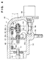
- Fig. 3 is a perspective view illustrating the rear-wheel steering mechanism 18 and Fig. 4 is a detail of the steering-angle-ratio adjusting mechanism 20 of the rear-wheel steering mechanism 18 in a direction of V-V of Fig. 3.
- the rear-wheel steering mechanism 18 comprises the steering-angle-ratio adjusting mechanism 20, hydraulic switch valve 32, rear-wheel steering rod 34, displacement transfer mechanism 36, and hydraulic power cylinder 38.
- the steering-angle-ratio adjusting mechanism 20 has an output rod 40, bevel gear 42, yaw shaft member 44, pendulum arm 46, and coupling rod 48. These are accommodated in a case 50 as shown in Fig. 4.
- the output rod 40 is supported by the case 50 and capable of oscillating in the direction of axis L3.
- the rear-wheel steering rod 34 is displaced in the direction of the axis L3 (to the vehicle width) through the displacement transfer mechanism 36 by stroke displacement to the axis L3. Accordingly, the rear wheels which connect to both ends of the rear-wheel steering rod 34 are steered.
- the bevel gear 42 is supported by the case 50 and capable of rotating around the axis L3 of the output rod 40 and axis L1. It is arranged so that as a pinion 52a of an end portion of the transfer shaft 52 which engages with the bevel gear 42 rotates around the axis L1 as the steering wheel 30 turns. That is, the front-wheel steering angle ⁇ F is inputted to the rear-wheel steering mechanism 18 through the transfer shaft 52 from the front-wheel steering mechanism 14.
- the yaw shaft member 44 has an axis L2 capable of locating on the same position as the axis L3 of the output rod 40 and is fixed to a yawing gear 54.
- the gear 54 is engaged with a worm gear 58 which rotates by a servomotor 56 controlled by the control unit 22, and is rotated around a vertical axis which intersects with the axis L2, thus making the yaw shaft member 44 rotate. That is, as apparent from the later description, the servomotor 56 can set the steering-angle-ratio variably in accordance with the position of rotated angle thereof.
- the pendulum arm 46 is connected to the yaw shaft member 44 capable of yawing around the axis L2 of the yaw shaft member 44 and a connecting position to the yaw shaft member 44 is determined so that the axis L4 of the pendulum arm 46 crosses an intersection of the rotating axis and axis L2 of the yaw shaft member 44.
- the coupling rod 48 has an axis L5 which is parallel to the axis L3 of the output rod 40, and is connected to the output rod 40, bevel gear 42, and pendulum arm 46.
- the coupling rod 48 is connected to the output rod 40 by screwing one of ends of the coupling rod 48 to a lever 40a fixed at the end of the output rod 40.
- the connection to the bevel gear 42 is performed by connecting the other end of the coupling rod 48 to a hole 42a formed in the bevel gear 42 at the point in a distance r from the axis L1 of the bevel gear 42.
- connection to the pendulum arm 46 is performed by connecting the pendulum arm 46 to a hole 60a of ball joint member 60, capable of rotating in all directions, which is provided at the end of the coupling rod 48.
- the coupling rod 48 is fixed with respect to the output rod 40, but it is capable of oscillating in the direction of axis L5 (that is, the direction of axis L3) with respect to the bevel gear 42, and it is also capable of oscillating in the direction of the axis L4 (that is, the direction which is perpendicular to the axis L3 in the figure) with respect to the pendulum arm 46.
- the axis L4 of the pendulum arm 46 inclines to the direction which is perpendicular to the axis L3 by revolution of the yaw shaft member 44 and the pendulum arm 46 oscillates in this inclined direction.
- an oscillating component in the direction which is perpendicular to the axis L3 is included and a change of included angle of the axes L4 and L5 is absorbed by the rotative operation of the ball joint member 60.
- the component in the direction which is perpendicular to the axis L3 in a force which is transferred to the coupling rod 48 from the pendulum arm 46 is absorbed in the above connecting point and a relative displacement in the above-described direction is enabled.
- connection between the pendulum arm 46 and coupling rod 48 in the steering-angle-ratio adjusting mechanism 20 can be arranged so as to be a relative displacement in the direction which is perpendicular to the axis L3, a locus of the connecting point of the pendulum arm 46 and coupling rod 48 when the pendulum 46 is rotated is a circular locus or elliptical locus on outer circumferencial surface of the cylinder in which a radius is r with the axis L3 as the center.
- Fig. 5 is a diagram illustrating a displacement of the output rod 40 when the axis L2 of the yaw shaft member 44 is inclined ⁇ degree to the axis L3 of the output rod 40 (that is, the axis L4 of the pendulum arm 46 is inclined ⁇ degree to the direction which is perpendicular to the axis L3).
- the pendulum arm 46 is oscillated either in the direction to the right or left, if the amount of oscillation is the same, displacement of the connecting point of the output rod 40 and coupling rod 48 is respectively “S" to the axis L3 and displacement of the output rod 40 is also "S" to the axis L3 since the output rod 40 and coupling rod 48 are fixedly connected.
- the displacement amounts of the output rod 40 to the left and right shown in Fig. 5 are respectively "S” if the oscillation amount of the pendulum arm 46 is equal to each other.
- the displacement "S” varies according to a degree of ⁇ even if the steering amount of the handle is the same in the oscillation toward the right and left and the amount of rotation of the bevel gear 42 is the same in the oscillation toward the right and left. Therefore, the steering-angle-ratio ⁇ S can be set and adjusted by setting and adjusting the inclination ⁇ of the yaw shaft member 44 by the control of the servomotor 56.
- the yaw shaft member 44 can be not only inclined in the counterclockwise direction, but also the clockwise direction. In such case, the oscillating direction of the output rod 40 with respect to the rotation of the bevel gear 42 is the opposite to the above case. Accordingly, the rear wheels can be steered to the in-phase or opposite phase with respect to the steering handle or front wheels.
- the steering-angle-ratio ⁇ S set and adjusted by the steering-angle-ratio adjusting mechanism 20 can be detected by the steering-angle-ratio sensor 28 provided in the yaw shaft member 44 based on the inclination ⁇ .
- the hydraulic switch valve 32 is comprised of a valve housing 62 and spool 64 which are adjustably accommodated in the housing 62 in the direction of the axis L6 which is parallel to the axis L3 of the output rod 40.
- the spool 64 is displaced by the output rod 40 and rear-wheel steering rod 34 through the displacement transfer mechanism 36.
- the displacement of the spool 64 controls to supply the oil pressure to the hydraulic power cylinder 38. That is, if the displacement is toward the right from the neutral position with respect to the valve housing 62, the oil pressure is supplied to a right oil chamber 66 of the hydraulic power cylinder 38, while if the displacement is toward the left, the oil pressure is supplied to the left oil chamber 68.
- the above rear-wheel steering rod 34 is extended to the direction of vehicle width which is parallel to the axis L3 of the rod 40, displaces to that direction, and steers the rear wheels connected to both ends of the rod 40 through a tie rod or knuckle arm which is not indicated in the figure.
- the above displacement is performed by the oil pressure in the hydraulic power cylinder 38.
- a centering spring 70 is provided with the rear-wheel steering rod 34.
- a fail-safe operation is performed by returning the rear-wheel steering rod 34 to the neutral position, by means of the centering spring 70 which positions the rod 34 to the position where the rear wheels are steered for straight drive.
- the hydraulic power cylinder 38 displaces the rear-wheel steering rod 34 to the vehicle width by the hydraulic compressive force and a piston 72 is directly fixed on the rear-wheel steering rod 34 and sealing members 74 and 76 which form the left oil chamber 68 and right oil chamber 66 are provided on the right and left of the piston 72.
- the sealing members 74 and 76 are fixed on the housing 78 of the hydraulic power cylinder 38, but these are capable of oscillating with respect to the rear-wheel steering rod 34.
- the displacement transfer mechanism 36 engages with the output rod 34, spool 64, and rear-wheel steering rod 34.
- the mechanism 36 is operated to the direction where the spool 64 is displaced to the predetermined direction by displacement amount of the output rod 40 and to the direction where the spool 64 is displaced to the opposite direction by displacement of the output rod 40.
- the displacement transfer mechanism 36 is comprised of a cross-shaped lever which has a vertical lever and lateral lever.
- the one end A of the vertical lever engages with the output rod 40 and the other end B engages with the rear-wheel steering rod 34.
- the one end C of the lateral lever engages with the case of the rear-wheel steering apparatus 10 fixed on the vehicle body and the other end D engages with the spool 64.
- the ends A, B, and D are respectively engaged with the output rod 40, rear-wheel steering rod 34, and spool 64 so that it is capable of oscillating in the direction of the axis, and that it is capable of oscillating and rotating in the other directions.
- the engaged end C is capable of rotating but incapable of moving by the ball joint.
- the rear-wheel steering apparatus 10 performs the phase inversion control by controlling the steering-angle-ratio adjusting mechanism 20 provided in the rear-wheel steering mechanism 18 which is mechanically connected to the front-wheel steering mechanism 14.
- the front wheels 12 are at steering angle 0 o
- the rear wheels can be mechanically and accurately maintained at the steering angle 0 o .
- Fig. 6 is a diagram illustrating the construction of the speed sensor 24.
- the speed sensor 24 is mounted with a member of the wheel or an output shaft of transmission so as to detect change of magnetic flux in a cut 100 placed in the member of the wheel or output shaft of the transmission.
- the characteristic is that the output of the magnetic flux change signal decreases when the number of evolution is small. Therefore, it is substantially impossible to detect the vehicle speed slower than 2 km/h. This causes inaccuracy in the calibration of the conventional yaw rate sensor.
- the flowchart of Fig. 7 shows an example of the control procedure in order to constitute the yaw rate sensor.
- the control procedure is a program driven when a switch 101 (Fig. 2) is pressed.
- step S2 the vehicle speed V from the sensor 24 is monitored.
- step S4 a steering angle ⁇ F from the sensor 26 is monitored.
- step S6 a state of the brake switch 80 is monitored.
- step S8 it is judged whether or not the brake switch is on under the condition where the vehicle speed is zero and the steering angle ⁇ F is less than ⁇ F0 .
- the present invention can be modified in various ways within the scope of the objects of this invention.
- the speed sensor and yaw rate sensor are used.
- this does not impose a limitation upon the present invention.
- the timing of calibration is set by an operator, however, this operation can be automated. That is, if the controller 22 automatically detects the timing which satisfies the condition of step S8 and performs calibration, the operator will not be bothered by the calibration operation.
- the present invention is a rear-wheel steering apparatus which controls to correct a steering angle of the rear wheels by inputting a yaw rate signal as a parameter, comprising: a yaw rate sensor for detecting a yaw rate signal; speed detection means for detecting a vehicle speed; steering-angle detection means for detecting a steering angle; and calibration means for calibrating the yaw rate sensor in a case where the vehicle speed detected by the vehicle speed detection means is substantially zero and the steering angle detected by the steering-angle detection means is less than a predetermined value.
Landscapes
- Engineering & Computer Science (AREA)
- Mechanical Engineering (AREA)
- Physics & Mathematics (AREA)
- Chemical & Material Sciences (AREA)
- Combustion & Propulsion (AREA)
- Transportation (AREA)
- General Physics & Mathematics (AREA)
- Mathematical Physics (AREA)
- Theoretical Computer Science (AREA)
- Automation & Control Theory (AREA)
- Steering Control In Accordance With Driving Conditions (AREA)
- Steering-Linkage Mechanisms And Four-Wheel Steering (AREA)
Applications Claiming Priority (3)
| Application Number | Priority Date | Filing Date | Title |
|---|---|---|---|
| JP7738392 | 1992-03-31 | ||
| JP4077383A JPH05278626A (ja) | 1992-03-31 | 1992-03-31 | 車両の後輪操舵装置 |
| JP77383/92 | 1992-03-31 |
Publications (3)
| Publication Number | Publication Date |
|---|---|
| EP0563885A2 true EP0563885A2 (fr) | 1993-10-06 |
| EP0563885A3 EP0563885A3 (en) | 1994-05-18 |
| EP0563885B1 EP0563885B1 (fr) | 1999-12-29 |
Family
ID=13632373
Family Applications (1)
| Application Number | Title | Priority Date | Filing Date |
|---|---|---|---|
| EP93105256A Expired - Lifetime EP0563885B1 (fr) | 1992-03-31 | 1993-03-30 | Appareil de direction de roues arrières pour véhicules avec indicateur de lacet et moyens de calibrage pour ce-ci, et procédé de calibrage d'un indicateur de lacet |
Country Status (4)
| Country | Link |
|---|---|
| EP (1) | EP0563885B1 (fr) |
| JP (1) | JPH05278626A (fr) |
| KR (1) | KR970011359B1 (fr) |
| DE (1) | DE69327418T2 (fr) |
Cited By (6)
| Publication number | Priority date | Publication date | Assignee | Title |
|---|---|---|---|---|
| FR2730064A1 (fr) * | 1995-01-30 | 1996-08-02 | Siemens Ag | Procede et montage pour compenser les erreurs de signal d'un capteur de vitesse d'embardee. |
| FR2749819A1 (fr) * | 1996-06-12 | 1997-12-19 | Lefranc Jacques | Dispositif d'assistance a la prise de virage en motocycle |
| EP0899543A3 (fr) * | 1997-08-25 | 2002-07-24 | Siemens Aktiengesellschaft | Procédé et dispositif pour la détermination de la vitesse de lacet d'un objet mobile |
| WO2010020844A1 (fr) * | 2008-08-21 | 2010-02-25 | Toyota Jidosha Kabushiki Kaisha | Appareil de direction de véhicule |
| US7684945B2 (en) | 2006-04-25 | 2010-03-23 | Adc Automotive Distance Control Systems Gmbh | Method for the calibration of a yaw rate measurement |
| EP2243686A3 (fr) * | 2009-04-23 | 2010-11-17 | Honda Motor Co., Ltd. | Direction assistée électrique |
Families Citing this family (4)
| Publication number | Priority date | Publication date | Assignee | Title |
|---|---|---|---|---|
| JP2010260430A (ja) * | 2009-05-01 | 2010-11-18 | Honda Motor Co Ltd | センサの基準点補正方法 |
| JP6233127B2 (ja) * | 2014-03-24 | 2017-11-22 | 株式会社デンソー | ジャイロセンサのオフセット補正装置、車両用ナビゲーション装置及びジャイロセンサのオフセット補正方法 |
| CN104960572B (zh) * | 2015-07-08 | 2017-08-25 | 武汉理工大学 | 具有四轮转向的商用车 |
| DE102024101453A1 (de) * | 2024-01-18 | 2025-07-24 | Schaeffler Technologies AG & Co. KG | Hinterachslenkungen und Verfahren zur Kalibrierung von Hinterachslenkungen |
Family Cites Families (6)
| Publication number | Priority date | Publication date | Assignee | Title |
|---|---|---|---|---|
| JPS62261575A (ja) * | 1986-05-07 | 1987-11-13 | Toyota Motor Corp | 検出ヨ−レ−ト補正装置 |
| GB8909074D0 (en) * | 1989-04-21 | 1989-06-07 | Lotus Group Plc | Vehicle control system |
| JPH03253471A (ja) * | 1990-03-02 | 1991-11-12 | Mazda Motor Corp | 車両用制御装置 |
| JPH03253470A (ja) * | 1990-03-02 | 1991-11-12 | Mazda Motor Corp | 車両用制御装置 |
| JPH03253469A (ja) * | 1990-03-02 | 1991-11-12 | Mazda Motor Corp | 車両用制御装置 |
| US5321616A (en) * | 1990-08-10 | 1994-06-14 | Matsushita Electric Industrial Co., Ltd. | Vehicle control apparatus |
-
1992
- 1992-03-31 JP JP4077383A patent/JPH05278626A/ja active Pending
-
1993
- 1993-03-06 KR KR1019930003362A patent/KR970011359B1/ko not_active Expired - Fee Related
- 1993-03-30 DE DE69327418T patent/DE69327418T2/de not_active Expired - Fee Related
- 1993-03-30 EP EP93105256A patent/EP0563885B1/fr not_active Expired - Lifetime
Cited By (10)
| Publication number | Priority date | Publication date | Assignee | Title |
|---|---|---|---|---|
| FR2730064A1 (fr) * | 1995-01-30 | 1996-08-02 | Siemens Ag | Procede et montage pour compenser les erreurs de signal d'un capteur de vitesse d'embardee. |
| GB2297621A (en) * | 1995-01-30 | 1996-08-07 | Siemens Ag | Method and circuit arrangement for compensating for the signal errors of a sensor |
| GB2297621B (en) * | 1995-01-30 | 1999-04-07 | Siemens Ag | Method and circuit arrangement for compensating for the signal errors of a sensor |
| FR2749819A1 (fr) * | 1996-06-12 | 1997-12-19 | Lefranc Jacques | Dispositif d'assistance a la prise de virage en motocycle |
| EP0899543A3 (fr) * | 1997-08-25 | 2002-07-24 | Siemens Aktiengesellschaft | Procédé et dispositif pour la détermination de la vitesse de lacet d'un objet mobile |
| US7684945B2 (en) | 2006-04-25 | 2010-03-23 | Adc Automotive Distance Control Systems Gmbh | Method for the calibration of a yaw rate measurement |
| WO2010020844A1 (fr) * | 2008-08-21 | 2010-02-25 | Toyota Jidosha Kabushiki Kaisha | Appareil de direction de véhicule |
| CN102131689A (zh) * | 2008-08-21 | 2011-07-20 | 丰田自动车株式会社 | 车辆转向设备 |
| US8731778B2 (en) | 2008-08-21 | 2014-05-20 | Toyota Jidosha Kabushiki Kaisha | Vehicle steering apparatus |
| EP2243686A3 (fr) * | 2009-04-23 | 2010-11-17 | Honda Motor Co., Ltd. | Direction assistée électrique |
Also Published As
| Publication number | Publication date |
|---|---|
| EP0563885A3 (en) | 1994-05-18 |
| JPH05278626A (ja) | 1993-10-26 |
| KR970011359B1 (ko) | 1997-07-10 |
| DE69327418D1 (de) | 2000-02-03 |
| EP0563885B1 (fr) | 1999-12-29 |
| KR930019500A (ko) | 1993-10-18 |
| DE69327418T2 (de) | 2000-07-06 |
Similar Documents
| Publication | Publication Date | Title |
|---|---|---|
| US6308123B1 (en) | Vehicle steering control system | |
| CN102105342B (zh) | 车辆转向设备及其控制方法 | |
| US6637543B2 (en) | Oversteer control for a motor vehicle | |
| WO2010128585A1 (fr) | Dispositif de commande d'angle de pincement de roue arrière et procédé d'étalonnage de la position de référence d'un actionneur électrique dans le dispositif de commande d'angle de pincement de roue arrière | |
| EP0563885A2 (fr) | Appareil de direction de roues arrières pour véhicules | |
| US5346030A (en) | Rear-wheel steering apparatus for vehicles | |
| EP0522554B1 (fr) | Dispositif de direction des roues arrière | |
| EP0472214B1 (fr) | Système de direction des quatre roues pour un véhicule | |
| EP0462553B1 (fr) | Méthode de détection de la position de référence d'un dispositif de direction de roue arrière de véhicule | |
| JPH06107206A (ja) | 車両の操舵装置 | |
| JPS59128053A (ja) | 車両の4輪操舵装置 | |
| JP3100780B2 (ja) | 車両用ヨーレートセンサの異常検出装置 | |
| JPH0431903B2 (fr) | ||
| JPH1159457A (ja) | 車両用操舵装置 | |
| JP2973615B2 (ja) | 四輪操舵装置 | |
| JPH05116640A (ja) | 四輪操舵装置 | |
| JPS62146775A (ja) | 車両の4輪操舵装置 | |
| JP3366685B2 (ja) | 後輪操舵装置の制御方法 | |
| JP2870893B2 (ja) | 移動農機 | |
| JP3320833B2 (ja) | 後輪操舵装置の制御方法 | |
| JPH05213221A (ja) | 車両の後輪操舵装置 | |
| JPH054274B2 (fr) | ||
| JPS63270283A (ja) | 車両の4輪操舵装置 | |
| JPH0597045A (ja) | 四輪操舵装置 | |
| JPH04303069A (ja) | 車両の後輪操舵装置 |
Legal Events
| Date | Code | Title | Description |
|---|---|---|---|
| PUAI | Public reference made under article 153(3) epc to a published international application that has entered the european phase |
Free format text: ORIGINAL CODE: 0009012 |
|
| AK | Designated contracting states |
Kind code of ref document: A2 Designated state(s): DE FR GB |
|
| PUAL | Search report despatched |
Free format text: ORIGINAL CODE: 0009013 |
|
| AK | Designated contracting states |
Kind code of ref document: A3 Designated state(s): DE FR GB |
|
| 17P | Request for examination filed |
Effective date: 19941018 |
|
| 17Q | First examination report despatched |
Effective date: 19951002 |
|
| GRAG | Despatch of communication of intention to grant |
Free format text: ORIGINAL CODE: EPIDOS AGRA |
|
| GRAG | Despatch of communication of intention to grant |
Free format text: ORIGINAL CODE: EPIDOS AGRA |
|
| GRAH | Despatch of communication of intention to grant a patent |
Free format text: ORIGINAL CODE: EPIDOS IGRA |
|
| GRAH | Despatch of communication of intention to grant a patent |
Free format text: ORIGINAL CODE: EPIDOS IGRA |
|
| GRAH | Despatch of communication of intention to grant a patent |
Free format text: ORIGINAL CODE: EPIDOS IGRA |
|
| GRAA | (expected) grant |
Free format text: ORIGINAL CODE: 0009210 |
|
| AK | Designated contracting states |
Kind code of ref document: B1 Designated state(s): DE FR GB |
|
| PG25 | Lapsed in a contracting state [announced via postgrant information from national office to epo] |
Ref country code: FR Free format text: LAPSE BECAUSE OF FAILURE TO SUBMIT A TRANSLATION OF THE DESCRIPTION OR TO PAY THE FEE WITHIN THE PRESCRIBED TIME-LIMIT Effective date: 19991229 |
|
| REF | Corresponds to: |
Ref document number: 69327418 Country of ref document: DE Date of ref document: 20000203 |
|
| PG25 | Lapsed in a contracting state [announced via postgrant information from national office to epo] |
Ref country code: GB Free format text: LAPSE BECAUSE OF NON-PAYMENT OF DUE FEES Effective date: 20000330 |
|
| EN | Fr: translation not filed | ||
| PLBE | No opposition filed within time limit |
Free format text: ORIGINAL CODE: 0009261 |
|
| GBPC | Gb: european patent ceased through non-payment of renewal fee |
Effective date: 20000330 |
|
| 26N | No opposition filed | ||
| PGFP | Annual fee paid to national office [announced via postgrant information from national office to epo] |
Ref country code: DE Payment date: 20020404 Year of fee payment: 10 |
|
| PG25 | Lapsed in a contracting state [announced via postgrant information from national office to epo] |
Ref country code: DE Free format text: LAPSE BECAUSE OF NON-PAYMENT OF DUE FEES Effective date: 20031001 |