EP0563992A2 - Méthode et appareil pour la fabrication d'éléments métalliques surfaces sur substrats - Google Patents
Méthode et appareil pour la fabrication d'éléments métalliques surfaces sur substrats Download PDFInfo
- Publication number
- EP0563992A2 EP0563992A2 EP93105519A EP93105519A EP0563992A2 EP 0563992 A2 EP0563992 A2 EP 0563992A2 EP 93105519 A EP93105519 A EP 93105519A EP 93105519 A EP93105519 A EP 93105519A EP 0563992 A2 EP0563992 A2 EP 0563992A2
- Authority
- EP
- European Patent Office
- Prior art keywords
- substrate
- layer
- intermediate carrier
- metal layers
- metal
- Prior art date
- Legal status (The legal status is an assumption and is not a legal conclusion. Google has not performed a legal analysis and makes no representation as to the accuracy of the status listed.)
- Granted
Links
Images




Classifications
-
- B—PERFORMING OPERATIONS; TRANSPORTING
- B41—PRINTING; LINING MACHINES; TYPEWRITERS; STAMPS
- B41M—PRINTING, DUPLICATING, MARKING, OR COPYING PROCESSES; COLOUR PRINTING
- B41M3/00—Printing processes to produce particular kinds of printed work, e.g. patterns
- B41M3/14—Security printing
-
- B—PERFORMING OPERATIONS; TRANSPORTING
- B42—BOOKBINDING; ALBUMS; FILES; SPECIAL PRINTED MATTER
- B42D—BOOKS; BOOK COVERS; LOOSE LEAVES; PRINTED MATTER CHARACTERISED BY IDENTIFICATION OR SECURITY FEATURES; PRINTED MATTER OF SPECIAL FORMAT OR STYLE NOT OTHERWISE PROVIDED FOR; DEVICES FOR USE THEREWITH AND NOT OTHERWISE PROVIDED FOR; MOVABLE-STRIP WRITING OR READING APPARATUS
- B42D25/00—Information-bearing cards or sheet-like structures characterised by identification or security features; Manufacture thereof
- B42D25/20—Information-bearing cards or sheet-like structures characterised by identification or security features; Manufacture thereof characterised by a particular use or purpose
- B42D25/29—Securities; Bank notes
-
- Y—GENERAL TAGGING OF NEW TECHNOLOGICAL DEVELOPMENTS; GENERAL TAGGING OF CROSS-SECTIONAL TECHNOLOGIES SPANNING OVER SEVERAL SECTIONS OF THE IPC; TECHNICAL SUBJECTS COVERED BY FORMER USPC CROSS-REFERENCE ART COLLECTIONS [XRACs] AND DIGESTS
- Y10—TECHNICAL SUBJECTS COVERED BY FORMER USPC
- Y10T—TECHNICAL SUBJECTS COVERED BY FORMER US CLASSIFICATION
- Y10T156/00—Adhesive bonding and miscellaneous chemical manufacture
- Y10T156/10—Methods of surface bonding and/or assembly therefor
- Y10T156/1002—Methods of surface bonding and/or assembly therefor with permanent bending or reshaping or surface deformation of self sustaining lamina
- Y10T156/1039—Surface deformation only of sandwich or lamina [e.g., embossed panels]
Definitions
- the invention relates to a method and a device for producing locally delimited metal layers on substrates with a possibly rough surface in the transfer process, in which the metal layers are prepared on a transfer surface and then transferred to the substrate.
- Metallic surface elements are of considerable importance in the area of anti-counterfeiting of valuable documents.
- metallic surfaces offer good copy protection due to their reflective properties, since the reflective surfaces cannot be reproduced using copying technology.
- metal printing inks are usually used to produce shiny metallic surface or printed images. Because of the granular fine structure, these processes can only be used for metallic surfaces, where the requirements for the reflection behavior of the surface are low and where no defined surface structures are required.
- holograms are a widely used type of counterfeit protection today. Because of the complex and costly production process, holograms can be imitated, if at all, only with relatively great effort and offer good copy protection because of their optical properties, which depend on the viewing angle. Apart from the security aspects, holograms are also often applied to value documents from an aesthetic point of view.
- Reflection holograms are usually generated either by means of specially prepared embossing matrices which have a surface relief corresponding to the interference pattern of the hologram, by embossing the surface relief into a hardened lacquer layer and then metallizing it and providing it with a protective lacquer layer.
- the relief of the embossing die can also be embossed directly into a thin metal layer and then provided with the protective lacquer layer. The metallization ensures sufficient brilliance of the hologram so that it can be recognized visually.
- the transfer belt is produced as a continuous belt, ie the metallization is carried out in a continuous process (e.g. in a vacuum evaporation system), only the desired areas are transferred to the document.
- the transfer of to Transferring surface areas can be accomplished in different ways.
- the adhesive layer can be printed in a certain pattern, so that the layer structure to be transferred (if necessary with large-scale heating) only adheres to the document in places or the printing stamp used in lamination has an outline shape that corresponds to the shape to be transferred, so that also the use of heat seal adhesive applied over a large area, only the areas of the adhesive layer to which the stamping die exerts pressure and heat are activated (DE-OS 33 08 831).
- EP-OS 0 338 378 describes a continuous process in which banknote paper in roll form is first printed on both sides and then provided with a holographic structure in certain areas.
- the lacquer is cured with UV radiation or electron beams.
- the varnish now adheres to the paper surface and has the holographic relief structure.
- this relief structure is metallized using masks in a vacuum evaporation system.
- the hologram area is provided with a protective layer in a further step.
- thermoplastic layer is transferred from a hot stamping foil to the document by means of a heated stamping die, the optical markings being simultaneously stamped into the thermoplastic layer.
- the carrier substrate is only removed after the embossing and the relief structure is then metallized.
- US Pat. No. 4,420,515 discloses a method in which an already metallized lacquer surface is provided with a relief structure.
- An endlessly circulating transfer belt is continuously metallized and brought into contact with a document that was selectively coated with a varnish.
- the varnish is hardened and binds the metal more strongly than the transfer ribbon and thus partially removes the metallization from this transfer ribbon when the transfer ribbon and document are separated.
- the metallized lacquer area on the substrate is embossed.
- the embossed relief has a low contour sharpness.
- the quality of the hologram is also impaired in this process.
- the embossing must be carried out with high pressure, so that the embossing dies are subject to high wear.
- the invention is therefore based on the object of providing a method and a device for applying locally limited metal layers to substrates, while avoiding the disadvantages mentioned above.
- a method and a device for flexible hologram production on difficult substrates and under difficult secondary conditions are to be specified.
- the invention is based on the basic idea that the production and transfer of a surface structure is only possible in an optimal form if the structures to be transferred are adopted as unadulterated as possible from the master structure and neither the structure nor the structure to be transferred to the final substrate of the master is changed or damaged.
- the structure to be transferred is not created by embossing an existing flat metal layer, but rather by “depositing” the metal layer on the master structure, the metal layer filling and capturing all structural elements of the master structure in a manner similar to a cast.
- the master and the metal layer thus have negative and positive structures that complement one another and are intimately connected.
- the two structures are only separated after the metal layer has been fixed on the end substrate and mechanically stabilized by the substrate and adhesive layer.
- structure is to be seen in general, i. H. Both an extremely smooth reflecting surface and any relief structure can be used as the structure. It is important according to the invention that the respectively selected or predetermined structure is implemented as unadulterated as possible as a positive or negative structure and is likewise transmitted unadulterated to the substrate.
- lacquer layer is intended to cover all materials and materials that are to be made so soft and sticky when the metal layer is transferred at the time of contact that the metal layer can be impressed into the layer with its back without damage, the metal layer being intimate with the lacquer layer connects and compensates for all unevenness between the substrate surface and the rear metal surface and on the other hand adheres the metal layer so firmly that, if necessary after an additional hardening phase, the metal layer can be removed completely from the master.
- Such measures can include further hardening of the lacquer layer, application of a protective lacquer layer, provision of blind embossing with different structures, overprinting with printing inks etc.
- a cylindrical pressure roller, an endless belt or a stamp etc. can be used as a carrier of the master structure z. B.
- the metal layer is produced using known metallization processes, such as vacuum evaporation, electrolysis or photolysis, and other special processes which are known in the art under special terms such as "gas jet deposition (GJD)", “spray deposition”, “laser deposition” etc.
- GJD gas jet deposition
- the varnish layer can be hardened in different ways. When using a liquid hot melt adhesive, this can be done, for example, simply by cooling, in the case of multicomponent paints by heating and, depending on the use of other substances, also by a different supply of energy, e.g. B. by UV radiation, microwave radiation, electron beam curing, etc.
- the method according to the invention is particularly suitable for the transfer of locally delimited metal layers, since both the metallization and the transfer process can be precisely defined and structured locally.
- the metallic surface elements are produced on an intermediate carrier with the master structure, from which they are transferred to the substrate.
- this procedure offers the advantage that any metallization method can be used, i. H. methods can also be used which would result in destruction or damage to the substrate if applied directly to the substrate.
- Particularly advantageous for metallization are photolytic processes, e.g. B. as described in DE-OS 38 40 199 or DE-OS 38 40 200, which offer the possibility the metallic surface elements in their outline shapes can be modified particularly easily, so that in this way, in a particularly economical form, series of different surface elements or also surface elements with varied additional information content can be produced.
- a varied variation of the continuously created metallizations can take place. This is possible, for example, by sensitizing the master in a locally limited form. All subsequent work steps can then be carried out over a large area, since metal is deposited only at the points where the catalyst is present. Alternatively, after extensive sensitization, the activation can also be carried out selectively. This variant is particularly advantageous because, for example, with the aid of a controlled UV laser, very fine and sharply delimited lines can also be displayed. These structures remain in their fine "line” even after subsequent full-surface wetting in wet chemical baths for electroless metallization. Ultimately, the local delimitation of the metal layers can also be produced by applying the wet chemical agents in a defined manner to a large-area sensitized and activated master surface.
- the intermediate carrier may not need to be conditioned again, i. H.
- the intermediate carrier is not completely cleaned in the last step, but only freed from metal residues.
- the embossing roller is coated with metal according to the invention.
- the method according to the invention makes it possible for the first time to carry out hologram production or embossing, metallization of the embossed hologram and transfer of the metallized hologram in a continuous workflow.
- the master structure is reproduced absolutely true to the original, since the metal layer completely molds the master structure. As already mentioned, this has an advantageous effect on the optical quality of the hologram diffraction structures, etc.
- Fig. 1 shows in schematic form the basic principle of the invention.
- the master 1 is provided with a metal layer in a first station.
- the master 1 has a surface structure 3 of some kind, in the case shown a surface relief.
- a metal layer 2 is applied to this relief 3 in such a way that the structure 3 is present in the metal layer 2 as an exact negative structure.
- the metal layer 2 is preferably delimited locally or has a defined outline contour.
- a substrate 4 is prepared, which can be almost any medium. In the present case, it is a security with a glued, naturally rough surface.
- a lacquer coating device is provided as a further work station, with which a locally delimited lacquer layer can be applied either on the metal layer 2 or on the substrate 4.
- the local delimitation of the lacquer layer preferably corresponds to that of the metal layer 2.
- the two contours differ from one another, whereby it should be noted that the metal layer is only subtracted from the master in the areas in which it coincides with the lacquer layer is.
- the lacquer layer 6 may have to be cured at least to the extent that additional adhesion to the metal layer 2 and the substrate 4 and an inherent strength is ensured, which allows peeling off the master while simultaneously stabilizing the metal layer 2.
- curing can take place in that the lacquer layer 6 is a heated hot-melt adhesive, which solidifies relatively quickly when the master 1 and the metal layer 2 are cooled after being brought together.
- substances can be used that harden under the influence of IR or UV rays, microwaves, electron beams, etc.
- the final hardening can, if desired, also take place at any later point in time.
- the metal layer transferred in this way to the substrate may, depending on the subsequent application, be subject to further work steps, such as, for. B. subject to equipment with a transparent protective lacquer layer.
- these further steps are familiar to the person skilled in the art and need not be explained in more detail here.
- FIG. 1 For reasons of clarity, a representation true to scale and detail has been omitted in FIG. 1 and the other figures. Rather, the figures show basic arrangements which allow the method according to the invention to be carried out. In the figures, functionally identical elements are provided with the same reference numbers.
- a cylindrical printing roller with a smooth surface is partially metalized electrolytically and brought into contact with an adhesive-coated substrate.
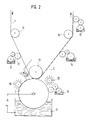
- the web-shaped substrate 4, in the present case paper, is conveyed by a transport system, which is indicated in FIG. 2 by the rollers 10. Before the web material 4 is fed to the printing roller 11, passes through There is a paint coating station 5. The web 4 is coated here with the aid of an engraving or stencil cylinder 12 in certain areas with a transparent adhesive.
- the substrate 4 passes through the transfer zone, which is formed by the cylindrical transfer roller 11 and a likewise cylindrical counter-pressure roller 13.
- the curing of the adhesive for. B. by polymerization with electron beams or UV radiation.
- the metal coating 2 is pulled off the intermediate carrier 11.
- the metallized area 2 can, if necessary, also be provided with a transparent protective lacquer layer over the entire or larger areas of the material web 4.
- the material web 4 provided with metallic surface elements 2 in this way can finally be fed to further printing stations 15 in order to print them with alphanumeric characters or patterns, which under certain circumstances can also cover parts of the metal coating 2.
- special printing inks mixed with feature substances instead of conventional printing inks, which can be transparent in the visual spectral range.
- fluorescent substances, magnetic or pearlescent pigments are suitable as characteristic substances.
- FIG. 3 shows the layer structure of the metallized substrate 4 after passing through the protective lacquer coating station 14.
- the adhesive layer 6 applied locally in station 5 is arranged directly on the substrate 4. Since this layer 6 is transparent and very thin and therefore does not impair the visual impression of the end product, its areal expansion does not have to correspond exactly to the dimensions of the metallization 2.
- the extent of the adhesive layer 6 must not be less than the intended metallization 2, because this would result in an incomplete metal transfer.
- a likewise transparent protective lacquer layer 16 In order to protect the metallization 2 from abrasion and destruction, it is covered by a likewise transparent protective lacquer layer 16.
- the intermediate carrier here the cylindrical roller 11
- the metallic surface elements 2 is provided with the metallic surface elements 2 to be transferred.
- the transfer roller 11 is metallized electrolytically.
- the parts of the cylinder that are not to be metallized are coated in the station 19 with electrically insulating material, e.g. B. with a layer of lacquer.
- electrically insulating material e.g. B. with a layer of lacquer.
- the roller 11 passes through a galvanic bath 17.
- the metal dissolved in the bath is deposited on the electrically conductive surface areas of the roller 11 due to the voltage applied to the transfer cylinder 11 and the bath that a metallic pattern is created on the roller surface.
- Chemical residues are removed in the following washing station 18.
- the metal coating 2 is now transferred to the substrate 4.
- the roller 11 in the station 20 is then cleaned of any metal residues. If the outline (or the shape) of the metal coating is to be changed, the electrically insulating coating of the roller 11 is also removed in the cleaning station 20. In the coating station 19, the roller 11 is finally prepared for the next metallization cycle.
- Fig. 4 shows a metallization station in which the The above-mentioned cylindrical transfer roller is partially metallized in a photolytic way and brought into contact with an adhesive-coated substrate.
- the pretreatment and aftertreatment of the substrate 4 and the transfer of the metallic areas is carried out analogously to example 1. For this reason, the corresponding additional processing stations have been omitted in FIG. 4.
- Photolysis is a modern metallization process that has been used successfully for some years in the metallic coating of semiconductor components (DE-OS 38 40 199) or in the production of metal fleece for shielding electrical fields (DE-OS 38 40 200) has been.
- the intermediate carrier 11 is wetted with a palladium acetate film.
- a palladium acetate film For this purpose, powdered palladium acetate in a solvent such as. As chloroform, dissolved and applied by dipping, spraying or spinning.
- Fig. 4 shows a representative immersion station 21. The solvent evaporates immediately and leaves a thin palladium acetate film, the thickness of which can be adjusted via the concentration of the solution and the application process.
- the parts of the printing roller to be metallized are exposed to UV radiation in order to produce a thin palladium layer by selective photo cleavage at the exposed locations.
- This palladium layer which is only a few nm thick, then serves as an activator for the subsequent chemical metallization, in which micrometer-thick copper, nickel and gold layers can be applied.
- 4 shows a metallization bath 23 in which the intermediate carrier roller 11 is immersed.
- the metallization can also be done by means of a suitable printing process, e.g. B. in screen printing, on the intermediate carrier 11 can be printed directly.
- the unexposed and thus non-metallized palladium acetate residues and liquid residues from the metallization bath 23, which have remained on the roller 11, are rinsed off.
- the intermediate carrier 11 is cleaned in station 25. Then the procedure described above is repeated cyclically.
- the finished substrate in this example has the same layer structure as in Example 1, which was described with reference to FIG. 3.
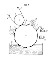
- a printing roller with a smooth surface it is also possible, for example, to use a cylindrical high-pressure roller (letterpress), as shown in FIG. 5.
- this roller is also metallized using the photolytic method.
- the pretreatment and aftertreatment of the substrate 4 proceeds analogously to Example 1.
- the process steps for the metallization of the high-pressure roller 26 proceed analogously to example 2.
- the raised areas 27 of the pressure roller 26 are wetted with palladium acetate 21 and irradiated with UV light 22 over a large area in accordance with the information to be transferred.
- the metal dissolved in the metallization bath 23 is deposited on the activated areas, while the unexposed areas are cleaned in the cleaning station 24.
- the adhesive previously applied to the substrate is hardened and thus binds the metal layer 2 to the substrate 4.
- the pressure areas 27 in station 25 are completely cleaned.
- an endless belt 28 with a smooth surface serves as an intermediate carrier, which is partially metallized by electrolytic means and brought into contact with the adhesive-coated substrate 4.
- the substrate is only locally coated with a component 29 of the lacquer which removes the metal coating 2 from the intermediate carrier 28.
- the substrate 4 is then transported through the transfer zone analogously to the preceding examples and possibly aftertreated in accordance with Example 1.
- the metallization station consists of an endless belt 28 which rotates over the rollers 30, 31 and is electrolytically metallized.
- the endless belt 28 is prepared in the stations 20 and 19 and then locally in the galvanic bath 17 metallized.
- the second component 32 of the releasing lacquer e.g. B. applied an adhesion promoter for the metal layer to be transferred and / or a hardener for the first component.
- the diffusion of the hardener together with the supply of energy which has to be matched to the materials used, accelerates the curing process and bonds the transferred metal layer very well to the substrate.
- This two-component adhesive can of course also be used in all the other examples described.
- FIG. 7 Another variant of a metallization station is shown in FIG. 7.
- the pretreatment or aftertreatment of the substrate 4 is carried out analogously to Example 1.
- FIG. 7 therefore only shows the devices necessary for the metallization of the endless belt 28 and the rollers 13 and 30 forming the transfer zone.
- the partial metallization of the intermediate carrier 28 takes place here analogously to Example 2 by the photolytic method.
- the endless belt 28 is wetted with the palladium acetate film 21, which is activated in places by UV radiation 22 for the metal accumulation in the metallization bath 23.
- the stations 24 and 25 ensure the cleaning of the belt 28 already described.
- 8 is likewise limited to the metallization station and the transfer zone.
- the endless belt 28 serving as an intermediate carrier is partially metallized by a vacuum coating over masks.
- the belt 28 is cleaned of any metal residues in station 33 before each metallization cycle.
- the areas to be coated are conditioned in the vacuum chamber 34 itself, if necessary with the aid of masks 35. Both the vacuum vapor deposition and the cathode ray sputtering method (sputtering) can be used as the vacuum coating method. As already explained, the transfer of the metallic areas takes place by curing or cooling the adhesive in the contact zone of substrate 4 and endless belt 28 between the rollers 13 and 30.
- the methods for local metallization of a substrate shown in FIGS. 2 to 8 and described in Examples 1-6 can also be used very advantageously for the reflective coating of a diffraction structure, preferably a hologram.
- the intermediate carrier is designed as an embossing mold, i. H. on its surface it bears the diffractive relief structure which is embossed into the lacquer on the substrate in accordance with the prior art.
- the lacquer can also be applied to the metallized areas of the intermediate carrier and simultaneously transferred to the substrate with the metal layer.
- the metallization according to the invention of the insensitive embossing die instead of the sensitive substrate allows chemical metallization with aggressive chemicals.
- metallization stations are described that use such a Have embossed intermediate carrier.
- a cylindrical printing roller with a relief-like surface structure is metallized partially or fully electrolytically and brought into contact with an adhesive-coated substrate.
- the device shown in FIG. 2 can in principle be adopted. Only the cylindrical pressure roller 11 must have a relief surface corresponding to the hologram.
- the substrate 4, e.g. B. a paper web, is preferably placed with an engraving or a stencil cylinder 12, locally coated with a varnish 5 at the locations where the hologram is to be embossed. Subsequently, the substrate 4 is transported into the embossing and metal transfer zone between the pressure roller 13 and the metallized embossing mold 36.
- the cylindrical embossing mold 36 has the hologram embossing structure placed in register with respect to the locally coated surfaces of the substrate 4.
- the surface relief of the embossing die 36 is metallized over the entire surface or partially according to the electrolytic method already described in Example 1.
- the metallization can also take place over the entire area, because the register-accurate transfer is determined by the coated locations on the substrate 4.
- a sharper contouring of the metal surfaces 2 is, however, partially Metallization of the die 36 reached.
- the relief structure is transferred to the lacquer true to the original.
- the lacquer is hardened e.g. B. by cooling, UV radiation or polymerization with electron beams.
- the hardened lacquer layer removes the metallization from the embossing mold 36.
- the cylindrical printing roller with smooth surface 11 is replaced by a likewise cylindrical embossing die 36 and metallized photolytically.
- the metallization devices described in Examples 4-6 which use an endless belt as an intermediate carrier, can also be used in the combined hologram embossing or metallization according to the invention.
- the endless belt 28 carries the hologram relief structure in these cases.
- FIG. 9 shows a detail from the embossing tape 37 metallized by photolytic means (FIG. 7) before it is brought into contact with the substrate 4.
- the endless belt 37 has a relief structure 38.
- the metal 2 has deposited on the palladium layer 39. It has exactly the outline shapes of the palladium layer 39 and reproduces the relief structure 38 true to the original.
- the simultaneous transfer of metallization and relief structure avoids losses in quality that result from the subsequent application of the mirroring, because the subsequently evaporated metal layer blurs the relief structures.
- the negative influence of the surface structure of the substrate is avoided because the lacquer layer compensates for the roughness of the substrate.
- the photolytic metallization of the embossing mold offers the possibility of producing finely structured metallic surfaces.
- This fact is also of great advantage when designing holograms in combination with other features.
- the hologram can be provided with a line or guilloche frame or rasterized so that a background print remains visible. It would also be conceivable to have cutouts in the form of characters or patterns to be provided in the metallization. Due to the variable exposure options of the palladium acetate film, a sequential numbering in the form of metallic numerals could also be provided on the hologram.
- Another basic variant is to do without the substrate.
- the paint cured directly on the metallic intermediate carrier and peeled off with the metal layer as a self-supporting film.
Landscapes
- Business, Economics & Management (AREA)
- Accounting & Taxation (AREA)
- Finance (AREA)
- Holo Graphy (AREA)
- Credit Cards Or The Like (AREA)
- Physical Vapour Deposition (AREA)
- Chemically Coating (AREA)
Applications Claiming Priority (2)
| Application Number | Priority Date | Filing Date | Title |
|---|---|---|---|
| DE4211235 | 1992-04-03 | ||
| DE4211235A DE4211235C2 (de) | 1992-04-03 | 1992-04-03 | Verfahren und Vorrichtung zur Herstellung metallischer Flächenelemente auf Substraten und deren Verwendung |
Publications (3)
| Publication Number | Publication Date |
|---|---|
| EP0563992A2 true EP0563992A2 (fr) | 1993-10-06 |
| EP0563992A3 EP0563992A3 (en) | 1995-01-18 |
| EP0563992B1 EP0563992B1 (fr) | 1998-07-15 |
Family
ID=6456002
Family Applications (1)
| Application Number | Title | Priority Date | Filing Date |
|---|---|---|---|
| EP93105519A Expired - Lifetime EP0563992B1 (fr) | 1992-04-03 | 1993-04-02 | Méthode et appareil pour la fabrication d'éléments métalliques surfaces sur substrats |
Country Status (5)
| Country | Link |
|---|---|
| US (1) | US5807456A (fr) |
| EP (1) | EP0563992B1 (fr) |
| JP (1) | JP3049646B2 (fr) |
| AT (1) | ATE168327T1 (fr) |
| DE (2) | DE4211235C2 (fr) |
Cited By (3)
| Publication number | Priority date | Publication date | Assignee | Title |
|---|---|---|---|---|
| WO2002037192A1 (fr) * | 2000-11-02 | 2002-05-10 | Tesa Scribos Gmbh | Procede pour produire des hologrammes |
| EP1509813B1 (fr) * | 2002-06-06 | 2015-09-23 | Constantia Teich GmbH | Feuille metallique infalsifiable |
| EP3150400A1 (fr) * | 2015-10-02 | 2017-04-05 | Hueck Folien Gesellschaft m.b.H. | Procede destine a la fabrication d'un element de securite |
Families Citing this family (21)
| Publication number | Priority date | Publication date | Assignee | Title |
|---|---|---|---|---|
| US6302989B1 (en) * | 1994-03-31 | 2001-10-16 | Giesecke & Devrient Gmbh | Method for producing a laminar compound for transferring optically variable single elements to objects to be protected |
| DE19746268A1 (de) * | 1997-10-20 | 1999-04-22 | Giesecke & Devrient Gmbh | Verfahren und Vorrichtung zur Herstellung eines Folienmaterials |
| DE19803755C2 (de) * | 1998-01-30 | 2001-03-15 | Ivoclar Ag Schaan | Lichthärtgerät |
| DE19819571A1 (de) | 1998-04-30 | 1999-11-04 | Giesecke & Devrient Gmbh | Wertdokument mit Sicherheitselement |
| DE19825836B4 (de) * | 1998-06-10 | 2006-10-05 | Stiebel Eltron Gmbh & Co. Kg | Verfahren zum Aufbringen wenigstens einer Dickschicht-Heizleiterbahn auf einen Wasserbehälter und Wasserbehälter |
| US6935230B1 (en) | 2000-05-12 | 2005-08-30 | Immersion Graphics Corporation | Liquid coating applicator and printing system with ink activator sprayer |
| ITMI20011914A1 (it) * | 2001-09-13 | 2003-03-13 | Elmiva S A S Di Walter Mantega | Procedimento per la realizzazione di documenti carte valori banconotee simili con elementi di sicurezza nonche' documento carta valori banc |
| US20040144479A1 (en) * | 2003-01-23 | 2004-07-29 | Peter Cueli | Preparation of novel physical transfer elements such as hot stamping foil and methods for using the same in producing chemically resistant bonds |
| US20040241404A1 (en) * | 2003-06-02 | 2004-12-02 | Klaser Technology Inc. | Paper with holographic pattern and manufacture of it |
| DE102004004713A1 (de) * | 2004-01-30 | 2005-09-01 | Leonhard Kurz Gmbh & Co. Kg | Sicherheitselement mit partieller Magnetschicht |
| US20060234067A1 (en) * | 2005-04-15 | 2006-10-19 | Klaser Technology Inc. | Laser gilding film containing curing coating and manufacture thereof |
| US20070102103A1 (en) * | 2005-11-07 | 2007-05-10 | Klaser Technology Inc. | Manufacturing method for printing circuit |
| CN101636235B (zh) * | 2007-02-20 | 2011-09-07 | 西门子公司 | 轧辊和/或辊子以及轧辊和/或辊子的制备方法 |
| US8242006B2 (en) | 2007-12-21 | 2012-08-14 | General Electric Company | Smooth electrode and method of fabricating same |
| US9005391B2 (en) * | 2009-06-12 | 2015-04-14 | Hazen Paper Company | Method and apparatus for transfer lamination |
| CN102667641A (zh) * | 2009-09-28 | 2012-09-12 | 宝洁公司 | 对聚合物膜基材赋予局部全息效应的方法 |
| DE102013005839A1 (de) | 2013-04-04 | 2014-10-09 | Giesecke & Devrient Gmbh | Sicherheitselement für Wertdokumente |
| KR101449272B1 (ko) * | 2013-04-22 | 2014-10-08 | 한국기계연구원 | 전사기반의 임프린팅 공정을 이용한 함몰패턴 제작방법 |
| EP3164684A4 (fr) * | 2014-07-02 | 2018-01-10 | Canon U.S. Life Sciences, Inc. | Procédé pour produire un canal microfluidique enfoui doté d'élément chauffant intégré |
| DE102015112909B3 (de) * | 2015-08-05 | 2017-02-09 | Leonhard Kurz Stiftung & Co. Kg | Verfahren und Vorrichtung zum Herstellen einer Mehrschichtfolie |
| FI127799B (en) * | 2017-06-02 | 2019-02-28 | Dispelix Oy | Process for producing a diffraction grating |
Family Cites Families (28)
| Publication number | Priority date | Publication date | Assignee | Title |
|---|---|---|---|---|
| US3009847A (en) * | 1956-09-20 | 1961-11-21 | Du Pont | Magnetic recording tape and process of making same |
| US3565978A (en) * | 1967-09-11 | 1971-02-23 | Xerox Corp | Replication of surface deformation images |
| US3922416A (en) * | 1972-08-18 | 1975-11-25 | Rca Corp | Medium for recording phase holograms |
| GB1477203A (en) * | 1974-02-11 | 1977-06-22 | Whiley Ltd G | Manufacture of image-bearing cards and other documents |
| US4339168A (en) * | 1978-02-06 | 1982-07-13 | Eidetic Images, Inc. | Holograms created from cylindrical hologram masters |
| NL8000967A (nl) * | 1980-02-15 | 1981-09-16 | Leer Koninklijke Emballage | Met metaal beklede samengestelde structuur alsmede werkwijze ter vervaardiging ervan. |
| DE3130032A1 (de) * | 1981-07-30 | 1983-02-17 | Agfa-Gevaert Ag, 5090 Leverkusen | Faelschungssicheres dokument |
| US4420515A (en) * | 1981-08-21 | 1983-12-13 | Sicpa Holding, S.A. | Metallization process for protecting documents of value |
| US4614367A (en) * | 1982-06-17 | 1986-09-30 | Rand Mcnally & Co. | Tamper-resisting multipart negotiable instruments |
| JPS5988780A (ja) * | 1982-11-08 | 1984-05-22 | アメリカン・バンク・ノ−ト・カムパニ− | 光回折記録体及び光回折パタ−ンを作る方法 |
| US4758296A (en) * | 1983-06-20 | 1988-07-19 | Mcgrew Stephen P | Method of fabricating surface relief holograms |
| US4893887A (en) * | 1983-12-12 | 1990-01-16 | E. I. Du Pont De Nemours And Company | Holographic image transfer process |
| DE3422911C1 (de) * | 1984-06-20 | 1985-09-05 | Leonhard Kurz GmbH & Co, 8510 Fürth | Praegefolie,insbesondere Heisspraegefolie,mit einer Magnetschicht |
| DE3422910C1 (de) * | 1984-06-20 | 1985-09-05 | Leonhard Kurz GmbH & Co, 8510 Fürth | Praegefolie,insbesondere Heisspraegefolie mit einer Magnetschicht |
| US4664734A (en) * | 1985-01-29 | 1987-05-12 | Fuji Photo Film Co., Ltd. | Process for producing a magnetic recording medium |
| EP0201323B1 (fr) * | 1985-05-07 | 1994-08-17 | Dai Nippon Insatsu Kabushiki Kaisha | Article comprenant un hologramme transparent |
| GB2181993A (en) * | 1985-10-31 | 1987-05-07 | Bpcc Holographic Security Syst | Method and means for preventing counterfeiting of documents |
| IT1226491B (it) * | 1986-07-01 | 1991-01-16 | Bruno Fabbiani | Documento di sicurezza provvisto di ologramma |
| US4725111A (en) * | 1986-07-29 | 1988-02-16 | American Bank Note Holographics, Inc. | Holograms embossed into metal surfaces |
| DE3638575A1 (de) * | 1986-11-12 | 1988-05-19 | Gao Ges Automation Org | Verfahren zur herstellung von identifikationskarten mit farblich abgedeckter magnetpiste |
| DE3765776D1 (de) * | 1987-04-22 | 1990-11-29 | Bloesch W Ag | Verfahren zur herstellung einer dekorativen oberflaechenstruktur mit einem hologramm oder einem beugungsmuster. |
| US4840757A (en) * | 1987-05-19 | 1989-06-20 | S. D. Warren Company | Replicating process for interference patterns |
| US4913858A (en) * | 1987-10-26 | 1990-04-03 | Dennison Manufacturing Company | Method of embossing a coated sheet with a diffraction or holographic pattern |
| DE69033853T2 (de) * | 1989-01-31 | 2002-06-13 | Dai Nippon Insatsu K.K., Tokio/Tokyo | Thermische Übertragungsaufzeichnungsverfahren und thermische Übertragungsbildempfangsblätter |
| DE59009271D1 (de) * | 1989-06-05 | 1995-07-27 | Landis & Gyr Betriebs Ag | Schichtverbund mit Beugungstrukturen. |
| NL8902949A (nl) * | 1989-11-29 | 1991-06-17 | Leer Koninklijke Emballage | Werkwijze voor het vervaardigen van een materiaal met interferentiepatroon, zoals holografische afbeeldingen. |
| GB9011457D0 (en) * | 1990-05-22 | 1990-07-11 | Amblehurst Ltd | Tamper indicating security tape |
| US5300169A (en) * | 1991-01-28 | 1994-04-05 | Dai Nippon Printing Co., Ltd. | Transfer foil having reflecting layer with fine dimple pattern recorded thereon |
-
1992
- 1992-04-03 DE DE4211235A patent/DE4211235C2/de not_active Expired - Fee Related
-
1993
- 1993-04-02 DE DE59308760T patent/DE59308760D1/de not_active Expired - Fee Related
- 1993-04-02 AT AT93105519T patent/ATE168327T1/de not_active IP Right Cessation
- 1993-04-02 EP EP93105519A patent/EP0563992B1/fr not_active Expired - Lifetime
- 1993-04-05 JP JP5078345A patent/JP3049646B2/ja not_active Expired - Fee Related
-
1996
- 1996-12-02 US US08/767,599 patent/US5807456A/en not_active Expired - Fee Related
Cited By (5)
| Publication number | Priority date | Publication date | Assignee | Title |
|---|---|---|---|---|
| WO2002037192A1 (fr) * | 2000-11-02 | 2002-05-10 | Tesa Scribos Gmbh | Procede pour produire des hologrammes |
| EP1509813B1 (fr) * | 2002-06-06 | 2015-09-23 | Constantia Teich GmbH | Feuille metallique infalsifiable |
| EP3150400A1 (fr) * | 2015-10-02 | 2017-04-05 | Hueck Folien Gesellschaft m.b.H. | Procede destine a la fabrication d'un element de securite |
| WO2017055634A1 (fr) * | 2015-10-02 | 2017-04-06 | Hueck Folien Gesellschaft M.B.H. | Procédé pour la production d'un élément de sécurité |
| US10618339B2 (en) | 2015-10-02 | 2020-04-14 | Hueck Folien Gesellschaft M.B.H. | Method for producing a security element |
Also Published As
| Publication number | Publication date |
|---|---|
| US5807456A (en) | 1998-09-15 |
| ATE168327T1 (de) | 1998-08-15 |
| EP0563992B1 (fr) | 1998-07-15 |
| JP3049646B2 (ja) | 2000-06-05 |
| DE4211235A1 (de) | 1993-12-02 |
| JPH0679987A (ja) | 1994-03-22 |
| EP0563992A3 (en) | 1995-01-18 |
| DE59308760D1 (de) | 1998-08-20 |
| DE4211235C2 (de) | 2003-04-17 |
Similar Documents
| Publication | Publication Date | Title |
|---|---|---|
| EP0563992B1 (fr) | Méthode et appareil pour la fabrication d'éléments métalliques surfaces sur substrats | |
| EP0810925B1 (fr) | Document infalsifiable pourvu d'un element de securite, et son procede de production | |
| EP1458577B1 (fr) | Element de securite et procede de fabrication associe | |
| EP0684908B1 (fr) | Document de securite et son procede de production | |
| EP3331699B1 (fr) | Procédé et dispositif de fabrication d'une feuille multicouche | |
| EP1087872B1 (fr) | Document de securite muni d'un element de securite | |
| WO1994018609A1 (fr) | Procede, support d'impression et dispositif permettant de reproduire des structures fines holographiques et d'autres reseaux de diffraction sur des produits d'impression | |
| DE69702321T2 (de) | Verbesserungen in bezug auf sicherheitsdokumente | |
| DE60100362T2 (de) | Dokument und Verfahren gegen dessen Verfälschung | |
| DE69012344T2 (de) | Holographisches prägeverfahren. | |
| EP0477535B1 (fr) | Support de données multicouche et méthode de sa fabrication | |
| DE69315985T2 (de) | Übertragungsverfahren und vorrichtung dafür | |
| EP3828002B1 (fr) | Document de valeurs | |
| DE3248990T (de) | Herstellung von geprägten Transferfolien und dergleichen | |
| DE4411404B4 (de) | Schichtverbund zum Übertragen von optisch variablen Einzelelementen auf zu sichernde Gegenstände, Sicherheitsdokument und ein Verfahren zur Herstellung eines Schichtverbunds | |
| DE68927899T2 (de) | Bebilderte Prägefolie für Wärmeübertragung, Artikel und Verfahren | |
| DE102017011917A1 (de) | Verfahren zum Herstellen eines mehrschichtigen Foliensicherheitselements | |
| EP0683903A1 (fr) | Procede, support d'impression et dispositif permettant de reproduire des structures fines holographiques et d'autres reseaux de diffraction sur des produits d'impression | |
| EP1390214A2 (fr) | Feuille d'estampage, procede pour sa production et pour le transfert d'une etiquette de la feuille d'estampage sur un substrat | |
| DE19780654B4 (de) | Prägezylinder für die Herstellung von Prägefolien | |
| DE2334039A1 (de) | Verbesserung der bindefaehigkeit von materialien mit glatter oberflaeche | |
| EP3486092B1 (fr) | Procédé de fabrication d'un élément de sécurité | |
| DE10201351B4 (de) | Druckverfahren und zugehörige Druckvorrichtung | |
| WO1999012748A1 (fr) | Dispositif pour la production d'un substrat a structure optiquement variable | |
| EP4067103A1 (fr) | Procédé de fabrication pour un élément de sécurité optiquement variable |
Legal Events
| Date | Code | Title | Description |
|---|---|---|---|
| PUAI | Public reference made under article 153(3) epc to a published international application that has entered the european phase |
Free format text: ORIGINAL CODE: 0009012 |
|
| AK | Designated contracting states |
Kind code of ref document: A2 Designated state(s): AT BE CH DE DK ES FR GB GR IE IT LI LU MC NL PT SE |
|
| PUAL | Search report despatched |
Free format text: ORIGINAL CODE: 0009013 |
|
| AK | Designated contracting states |
Kind code of ref document: A3 Designated state(s): AT BE CH DE DK ES FR GB GR IE IT LI LU MC NL PT SE |
|
| 17P | Request for examination filed |
Effective date: 19950717 |
|
| 17Q | First examination report despatched |
Effective date: 19950816 |
|
| GRAG | Despatch of communication of intention to grant |
Free format text: ORIGINAL CODE: EPIDOS AGRA |
|
| GRAG | Despatch of communication of intention to grant |
Free format text: ORIGINAL CODE: EPIDOS AGRA |
|
| GRAH | Despatch of communication of intention to grant a patent |
Free format text: ORIGINAL CODE: EPIDOS IGRA |
|
| GRAH | Despatch of communication of intention to grant a patent |
Free format text: ORIGINAL CODE: EPIDOS IGRA |
|
| GRAA | (expected) grant |
Free format text: ORIGINAL CODE: 0009210 |
|
| AK | Designated contracting states |
Kind code of ref document: B1 Designated state(s): AT BE CH DE DK ES FR GB GR IE IT LI LU MC NL PT SE |
|
| PG25 | Lapsed in a contracting state [announced via postgrant information from national office to epo] |
Ref country code: NL Free format text: LAPSE BECAUSE OF FAILURE TO SUBMIT A TRANSLATION OF THE DESCRIPTION OR TO PAY THE FEE WITHIN THE PRESCRIBED TIME-LIMIT Effective date: 19980715 Ref country code: IT Free format text: LAPSE BECAUSE OF FAILURE TO SUBMIT A TRANSLATION OF THE DESCRIPTION OR TO PAY THE FEE WITHIN THE PRESCRIBED TIME-LIMIT;WARNING: LAPSES OF ITALIAN PATENTS WITH EFFECTIVE DATE BEFORE 2007 MAY HAVE OCCURRED AT ANY TIME BEFORE 2007. THE CORRECT EFFECTIVE DATE MAY BE DIFFERENT FROM THE ONE RECORDED. Effective date: 19980715 Ref country code: GR Free format text: LAPSE BECAUSE OF NON-PAYMENT OF DUE FEES Effective date: 19980715 Ref country code: ES Free format text: THE PATENT HAS BEEN ANNULLED BY A DECISION OF A NATIONAL AUTHORITY Effective date: 19980715 |
|
| REF | Corresponds to: |
Ref document number: 168327 Country of ref document: AT Date of ref document: 19980815 Kind code of ref document: T |
|
| REG | Reference to a national code |
Ref country code: CH Ref legal event code: NV Representative=s name: PATENTANWAELTE SCHAAD, BALASS, MENZL & PARTNER AG Ref country code: CH Ref legal event code: EP |
|
| GBT | Gb: translation of ep patent filed (gb section 77(6)(a)/1977) |
Effective date: 19980716 |
|
| REF | Corresponds to: |
Ref document number: 59308760 Country of ref document: DE Date of ref document: 19980820 |
|
| REG | Reference to a national code |
Ref country code: IE Ref legal event code: FG4D Free format text: GERMAN |
|
| PG25 | Lapsed in a contracting state [announced via postgrant information from national office to epo] |
Ref country code: SE Free format text: LAPSE BECAUSE OF FAILURE TO SUBMIT A TRANSLATION OF THE DESCRIPTION OR TO PAY THE FEE WITHIN THE PRESCRIBED TIME-LIMIT Effective date: 19981015 Ref country code: PT Free format text: LAPSE BECAUSE OF FAILURE TO SUBMIT A TRANSLATION OF THE DESCRIPTION OR TO PAY THE FEE WITHIN THE PRESCRIBED TIME-LIMIT Effective date: 19981015 Ref country code: DK Free format text: LAPSE BECAUSE OF FAILURE TO SUBMIT A TRANSLATION OF THE DESCRIPTION OR TO PAY THE FEE WITHIN THE PRESCRIBED TIME-LIMIT Effective date: 19981015 |
|
| ET | Fr: translation filed | ||
| NLV1 | Nl: lapsed or annulled due to failure to fulfill the requirements of art. 29p and 29m of the patents act | ||
| PG25 | Lapsed in a contracting state [announced via postgrant information from national office to epo] |
Ref country code: IE Free format text: LAPSE BECAUSE OF NON-PAYMENT OF DUE FEES Effective date: 19990219 |
|
| REG | Reference to a national code |
Ref country code: IE Ref legal event code: FD4D |
|
| PG25 | Lapsed in a contracting state [announced via postgrant information from national office to epo] |
Ref country code: LU Free format text: LAPSE BECAUSE OF NON-PAYMENT OF DUE FEES Effective date: 19990402 |
|
| PLBQ | Unpublished change to opponent data |
Free format text: ORIGINAL CODE: EPIDOS OPPO |
|
| PLBI | Opposition filed |
Free format text: ORIGINAL CODE: 0009260 |
|
| PG25 | Lapsed in a contracting state [announced via postgrant information from national office to epo] |
Ref country code: BE Free format text: LAPSE BECAUSE OF NON-PAYMENT OF DUE FEES Effective date: 19990430 |
|
| PLAB | Opposition data, opponent's data or that of the opponent's representative modified |
Free format text: ORIGINAL CODE: 0009299OPPO |
|
| PLBF | Reply of patent proprietor to notice(s) of opposition |
Free format text: ORIGINAL CODE: EPIDOS OBSO |
|
| 26 | Opposition filed |
Opponent name: DE LA RUE INTERNATIONAL LIMITED Effective date: 19990414 |
|
| R26 | Opposition filed (corrected) |
Opponent name: DE LA RUE INTERNATIONAL LIMITED Effective date: 19990412 |
|
| PLBF | Reply of patent proprietor to notice(s) of opposition |
Free format text: ORIGINAL CODE: EPIDOS OBSO |
|
| BERE | Be: lapsed |
Owner name: G.- FUR AUTOMATION UND ORGANISATION M.B.H. GAO Effective date: 19990430 |
|
| PG25 | Lapsed in a contracting state [announced via postgrant information from national office to epo] |
Ref country code: MC Free format text: LAPSE BECAUSE OF NON-PAYMENT OF DUE FEES Effective date: 19991031 |
|
| PLBF | Reply of patent proprietor to notice(s) of opposition |
Free format text: ORIGINAL CODE: EPIDOS OBSO |
|
| PLBL | Opposition procedure terminated |
Free format text: ORIGINAL CODE: EPIDOS OPPC |
|
| PLBM | Termination of opposition procedure: date of legal effect published |
Free format text: ORIGINAL CODE: 0009276 |
|
| 27C | Opposition proceedings terminated |
Effective date: 20010705 |
|
| REG | Reference to a national code |
Ref country code: GB Ref legal event code: IF02 |
|
| PGFP | Annual fee paid to national office [announced via postgrant information from national office to epo] |
Ref country code: AT Payment date: 20030424 Year of fee payment: 11 |
|
| PGFP | Annual fee paid to national office [announced via postgrant information from national office to epo] |
Ref country code: CH Payment date: 20030425 Year of fee payment: 11 |
|
| PG25 | Lapsed in a contracting state [announced via postgrant information from national office to epo] |
Ref country code: AT Free format text: LAPSE BECAUSE OF NON-PAYMENT OF DUE FEES Effective date: 20040402 |
|
| PG25 | Lapsed in a contracting state [announced via postgrant information from national office to epo] |
Ref country code: LI Free format text: LAPSE BECAUSE OF NON-PAYMENT OF DUE FEES Effective date: 20040430 Ref country code: CH Free format text: LAPSE BECAUSE OF NON-PAYMENT OF DUE FEES Effective date: 20040430 |
|
| REG | Reference to a national code |
Ref country code: CH Ref legal event code: PL |
|
| PGFP | Annual fee paid to national office [announced via postgrant information from national office to epo] |
Ref country code: DE Payment date: 20070625 Year of fee payment: 15 |
|
| PGFP | Annual fee paid to national office [announced via postgrant information from national office to epo] |
Ref country code: GB Payment date: 20070425 Year of fee payment: 15 |
|
| PGFP | Annual fee paid to national office [announced via postgrant information from national office to epo] |
Ref country code: FR Payment date: 20070418 Year of fee payment: 15 |
|
| GBPC | Gb: european patent ceased through non-payment of renewal fee |
Effective date: 20080402 |
|
| PG25 | Lapsed in a contracting state [announced via postgrant information from national office to epo] |
Ref country code: DE Free format text: LAPSE BECAUSE OF NON-PAYMENT OF DUE FEES Effective date: 20081101 |
|
| REG | Reference to a national code |
Ref country code: FR Ref legal event code: ST Effective date: 20081231 |
|
| PG25 | Lapsed in a contracting state [announced via postgrant information from national office to epo] |
Ref country code: FR Free format text: LAPSE BECAUSE OF NON-PAYMENT OF DUE FEES Effective date: 20080430 |
|
| PG25 | Lapsed in a contracting state [announced via postgrant information from national office to epo] |
Ref country code: GB Free format text: LAPSE BECAUSE OF NON-PAYMENT OF DUE FEES Effective date: 20080402 |