EP0564113B1 - Druckentlastungsventil für einen Reifen - Google Patents
Druckentlastungsventil für einen Reifen Download PDFInfo
- Publication number
- EP0564113B1 EP0564113B1 EP93301892A EP93301892A EP0564113B1 EP 0564113 B1 EP0564113 B1 EP 0564113B1 EP 93301892 A EP93301892 A EP 93301892A EP 93301892 A EP93301892 A EP 93301892A EP 0564113 B1 EP0564113 B1 EP 0564113B1
- Authority
- EP
- European Patent Office
- Prior art keywords
- port
- spool
- valve
- air
- opening
- Prior art date
- Legal status (The legal status is an assumption and is not a legal conclusion. Google has not performed a legal analysis and makes no representation as to the accuracy of the status listed.)
- Expired - Lifetime
Links
Images

Classifications
-
- F—MECHANICAL ENGINEERING; LIGHTING; HEATING; WEAPONS; BLASTING
- F16—ENGINEERING ELEMENTS AND UNITS; GENERAL MEASURES FOR PRODUCING AND MAINTAINING EFFECTIVE FUNCTIONING OF MACHINES OR INSTALLATIONS; THERMAL INSULATION IN GENERAL
- F16K—VALVES; TAPS; COCKS; ACTUATING-FLOATS; DEVICES FOR VENTING OR AERATING
- F16K17/00—Safety valves; Equalising valves, e.g. pressure relief valves
-
- B—PERFORMING OPERATIONS; TRANSPORTING
- B60—VEHICLES IN GENERAL
- B60C—VEHICLE TYRES; TYRE INFLATION; TYRE CHANGING; CONNECTING VALVES TO INFLATABLE ELASTIC BODIES IN GENERAL; DEVICES OR ARRANGEMENTS RELATED TO TYRES
- B60C23/00—Devices for measuring, signalling, controlling, or distributing tyre pressure or temperature, specially adapted for mounting on vehicles; Arrangement of tyre inflating devices on vehicles, e.g. of pumps or of tanks; Tyre cooling arrangements
- B60C23/02—Signalling devices actuated by tyre pressure
- B60C23/04—Signalling devices actuated by tyre pressure mounted on the wheel or tyre
- B60C23/0491—Constructional details of means for attaching the control device
- B60C23/0496—Valve stem attachments positioned outside of the tyre chamber
-
- B—PERFORMING OPERATIONS; TRANSPORTING
- B60—VEHICLES IN GENERAL
- B60C—VEHICLE TYRES; TYRE INFLATION; TYRE CHANGING; CONNECTING VALVES TO INFLATABLE ELASTIC BODIES IN GENERAL; DEVICES OR ARRANGEMENTS RELATED TO TYRES
- B60C23/00—Devices for measuring, signalling, controlling, or distributing tyre pressure or temperature, specially adapted for mounting on vehicles; Arrangement of tyre inflating devices on vehicles, e.g. of pumps or of tanks; Tyre cooling arrangements
- B60C23/001—Devices for manually or automatically controlling or distributing tyre pressure whilst the vehicle is moving
- B60C23/003—Devices for manually or automatically controlling or distributing tyre pressure whilst the vehicle is moving comprising rotational joints between vehicle-mounted pressure sources and the tyres
- B60C23/00354—Details of valves
-
- B—PERFORMING OPERATIONS; TRANSPORTING
- B60—VEHICLES IN GENERAL
- B60C—VEHICLE TYRES; TYRE INFLATION; TYRE CHANGING; CONNECTING VALVES TO INFLATABLE ELASTIC BODIES IN GENERAL; DEVICES OR ARRANGEMENTS RELATED TO TYRES
- B60C23/00—Devices for measuring, signalling, controlling, or distributing tyre pressure or temperature, specially adapted for mounting on vehicles; Arrangement of tyre inflating devices on vehicles, e.g. of pumps or of tanks; Tyre cooling arrangements
- B60C23/001—Devices for manually or automatically controlling or distributing tyre pressure whilst the vehicle is moving
- B60C23/003—Devices for manually or automatically controlling or distributing tyre pressure whilst the vehicle is moving comprising rotational joints between vehicle-mounted pressure sources and the tyres
- B60C23/00363—Details of sealings
-
- B—PERFORMING OPERATIONS; TRANSPORTING
- B60—VEHICLES IN GENERAL
- B60C—VEHICLE TYRES; TYRE INFLATION; TYRE CHANGING; CONNECTING VALVES TO INFLATABLE ELASTIC BODIES IN GENERAL; DEVICES OR ARRANGEMENTS RELATED TO TYRES
- B60C23/00—Devices for measuring, signalling, controlling, or distributing tyre pressure or temperature, specially adapted for mounting on vehicles; Arrangement of tyre inflating devices on vehicles, e.g. of pumps or of tanks; Tyre cooling arrangements
- B60C23/001—Devices for manually or automatically controlling or distributing tyre pressure whilst the vehicle is moving
- B60C23/003—Devices for manually or automatically controlling or distributing tyre pressure whilst the vehicle is moving comprising rotational joints between vehicle-mounted pressure sources and the tyres
- B60C23/00372—Devices for manually or automatically controlling or distributing tyre pressure whilst the vehicle is moving comprising rotational joints between vehicle-mounted pressure sources and the tyres characterised by fluid diagrams
Definitions
- This invention relates to a selectively operative relief valve having application to vehicle tires and adapted for use with central tire inflation systems (CTI Systems or CTIS) also known as on-board inflation systems or traction systems.
- CTI Systems central tire inflation systems
- Such systems monitor and vary tire pressure from a remote location on the vehicle while the vehicle is at rest and/or in motion.
- air pressure in vehicle tires can be varied to change tractive ability of the tires depending on the condition of the tire's operating surface, e.g., pavement, snow, off-road, etc.
- the tire pressure can be manually varied at each tire, or automatically or semi-automatically varied via CTI systems such as disclosed in the above mentioned patents and applications.
- vehicle height can be reduced by decreasing tire pressure. The amount of height reduction, of course, depends on tire profile. Hence, the greater the tire profile the more the vehicle height may be reduced.
- the selectively operative relief valve disclosed hereinafter may be employed to reduce tire pressure to a predetermined amount in vehicles with or without CTI systems.
- a valve can be provided which is selectively operative to reduce a fluid pressure to a predetermined amount.
- such a valve can be provided for reducing the pressure of tires on a vehicle and thereby reduce the vehicle height.
- a vehicle comprises at least one valve assembly, at least one rotatably mounted wheel including a tire supported thereon and having an inflatable volume, and air supply means for providing the volume with normal operating pressure greater than a first predetermined amount and less than a greater second predetermined amount.
- the valve assembly includes a valve housing affixed to the wheel and having a first port fluidly communicating with air pressure in the volume and having a vent port and a first valving means disposed in the housing and biased toward a closed position by a closing force of a spring means and toward an open position by an opening force of the air pressure at the first port.
- the first valving means is operative in the closed and open positions respectively to prevent and allow air flow from the first port to the vent port.
- Blocker means is provided for preventing the opening of the first valving means in response to the air pressure at the first port being between the first and second predetermined amounts in response to selective movement of an actuation means from a vent position to a nonvent position.
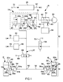
- the schematic of Figure 1 illustrates a CTIS 10 for a vehicle having system components mounted on a body/chassis represented by a bracket 12 and components mounted on an axle assembly represented by a bracket 14.
- the axle assembly includes left and right wheel assemblies 16,18.
- the vehicle is preferably, but not necessarily, of the heavy duty truck type or special duty type.
- the axle assembly may be a steer or nonsteer axle, a drive or nondrive axle, and/or a tandem axle.
- the wheel assembly may be of the single or dual wheel type.
- the CTIS measures and controls the inflation pressure of interior volumes 20a,22a of tires 20,22 mounted on wheels 24,26 of the wheel assemblies.
- the CTIS herein controls tire pressure of groups of tires, e.g., the tires on a steer axle, single or tandem drive axles, and in some installations tires on trailer axles.
- the chassis mounted components include a microcontroller 28, a vehicle operator control panel 29 shown in Figure 2, a source of pressurized air including a compressor 30 normally driven by the vehicle engine and an air tank 32 connected to a pneumatic control assembly 34 via a conduit 36 and to a vehicle brake system 38 via a conduit 40, an air manifold 42, a manifold air pressure sensor 44, a vehicle speed sensor 46, an axle valve 48 fluidly connected between manifold 42 and a T-connector 50 in a conduit 52 extending between the left and right tires of axle assembly 14. Any additional number of axle valves 53 may be provided for other axle assemblies. Alternatively, the axle valves may be configured to separately communicate the left and right tire volumes with manifold 42.
- Conduit 52 fluidly communicates with each tire volume 20a,22a via rotary seal assemblies 54,56, each having a non-rotatable port 54a,56a and a rotatable port 54b,56b, wheel valves 58,60, and selectively operative pressure relief valves 59,61 explained further hereinafter.
- rotary seals may be seen by reference to U.S. Patents 4,640,331; 4,804,027; 4,883,106 and 5,174,839.
- Each valve 58,60 includes an inlet 58a,60a communicating with conduit 52 via the associated rotary seal and an outlet 58b,60b communicating with the associated tire volume via relief valves 59,61.
- each valve includes valve means (58d,60d) for venting the associated tire volume to a vent or atmospheric opening 58c,60c in response to some form of command from microcontroller 28.
- the atmospheric opening may be at the wheel valve, as disclosed in U.S. Patents 4,678,017; 4,782,879; 4,922,946 and 5,253,687.
- the atmospheric opening may be remote from the wheel valve as disclosed in U.S. Patent 4,640,331, therein the atmospheric opening is provided by a quick release valve positioned in lieu of T-connector 50.
- Wheel valves 58,60 block air communication between the tire volumes 20a,22a and the associated valve inlets 58a,60a and atmospheric openings 58c,60c when air pressure at the inlet is substantially at atmospheric pressure.
- valve means 58d,60d of the valves allow fluid communication of the tire volumes with conduit 52.
- the valve means allow fluid communication of the tire volumes with the associated atmospheric openings 58c,60c.
- the CTIS may be provided with wheel valves which are closed when air pressure at the inlets is substantially equal to atmospheric pressure, open for inflating the tires when the inlet air pressure is above a first predetermined minimum, and in a vent position when the inlet pressure is a predetermined pressure above atmospheric pressure and below tire pressure.
- Microcontroller 28 includes a programmed microprocessor device/devices for processing and issuing command output signals via an output wiring harness 62. Harness 62 is connected to control panel 29 via a wiring harness 64, to pneumatic controller assembly 34 via conductors 66a,66b,66c and to axle valves 48,53 via conductors 68,70. The output signals are generated in accordance with known logic rules and in response to input signals received via an input wiring harness 72. Details of programming such microprocessor devices are known and rather straightforward given a flow diagram for the program.
- Input harness 72 receives signals from control panel 29 via a wiring harness 74, manifold pressure signals for pressure sensor 44 via a conductor 76, vehicle speed signals from speed sensor 46 via a conductor 78, and an air source pressure signal from a conductor 80 connected to a pressure sensor 82 on air tank 32.
- Microcontroller 28 renders the CTIS inoperative whenever the air source pressure signal indicates that the air source pressure is less than needed for safe operation of the vehicle brakes.
- CTIS microcontroller 28 is programmed to issue a tire pressure check command at vehicle start-up and periodically during vehicle operation. If the pressure check indicates that current tire pressure P C is greater than or less than a demand pressure P D , the controller issues either a deflate or inflate command.
- Operator control panel 29 includes light emitting push switches 29a,29b,29c,29d,29e respectively labeled “Highway”, “Cross-Country”, “Sand-Mud”, “Emergency”, and "Run Flat". Of course more or fewer switches may be provided. Additional detail concerning panel 29 may be seen by reference to U.S. Patent 4,754,792 and European Patent 0,297,837. Switches 29a through 29d instruct the microcontroller to maintain the vehicle tires at a demand pressure P D corresponding to the labeled type operation of switches 29a-29d.
- activation of switch 29a may correspond to a tire pressure of 3.02 bar (45 psi)
- switch 29b corresponds to a pressure of 2.35 bar (35 psi)
- switch 29c corresponds to a pressure of 1.68 bar (25 psi)
- switch 29d corresponds to a pressure of 0.8 bar (12 psi).
- the microcontroller may be programmed to override the reduced pressure setting of switches 29b,29c,29d when the vehicle exceeds a predetermined speed, e.g., 65 Km/hr (40 MPH).
- Activation of Run-Flat switch 29e instructs the microcontroller to increase the pressure check frequency and to maintain tire pressure corresponding to which switch 29a-29d is activated.
- Pneumatic control assembly 34 includes a pressure check and inflate valve 84, a vacuum and manifold vent valve 86, and a vacuum generator 88 including a solenoid valve 90 connected to the air source 32 and a venturi 92.
- Valve 84 has an inlet connected to the positive pressure of the air source via conduit 36 and an outlet connected to manifold 42.
- Valve 86 has an inlet connected to manifold 42 and an outlet connected via a conduit 94 to a small orifce 96 opening into the throat of the venturi.
- the venturi produces a vacuum or negative air pressure in conduit 94 relative to ambient atmospheric air pressure in response to a deflate signal from the microcontroller opening solenoid valve 90 to allow a stream of air from the air source to flow through the venturi.
- Conduit 94 is also connected to a one-way vent valve 98 for effecting rapid venting of positive air pressure in conduit 94.
- Vent valve 98 includes a valving member 100 drawn to a closed position in response to a negative air pressure in conduit 94 and moved to the open position against a biasing force in response to positive pressure air in conduit 94.
- CTIS 10 is designed to automatically maintain tire pressure at or near demand pressure P D selected by control panel 29 in accordance with microcontroller programming.
- the vehicle operator has the capability of commanding the system to decrease or increase tire pressure for improving tire traction or increasing load carrying capacity of the vehicle by merely activating the appropriate control panel switch.
- the system automatically increases tire pressure if the vehicle speed, as monitored by speed sensor 46, exceeds a predetermined speed for the selected tire pressure.
- controller 28 When the vehicle ignition is energized and pressure switch 82 is closed, controller 28 initiates a pressure check sequence of the tires on each of the axle assemblies. If tire pressure of any of the axles is found to be a predetermined amount less than demand pressure, an inflation sequence is initiated for the axle or axles effected. During vehicle operation, the microcontroller automatically initiates periodic pressure check sequences. When enhanced or maximum traction is required, the vehicle operator may command reduced tire pressure by pushing the appropriate switches on control panel 29; if the vehicle speed is greater than a predetermined amount for the selected reduced pressure, the microcontroller will not initiate the appropriate pressure deflation sequence.
- a pressure check sequence is initiated for axle assembly 14 by energizing valves 86,53 to the closed positions and momentarily energizing valve 84 to the open position to provide positive air pressure sufficient to move valving means of wheel valves 58,60 to positions intercommunicating the inlets and outlets thereof.
- De-energization of valve 84 returns the valving member therein to the closed position. With valve 84 closed and valves 48,58,60 open, the pressure in manifold 42 and conduit 52 soon equalizes to tire pressure.
- the microcontroller reads this pressure via electrical signals from sensor 44 and initiates inflate/deflate sequences as required. If no further sequence is required, vacuum valve 86 is de-energized to effect its open position, thereby connecting the wheel valve assembly inlet ports to the vent through vacuum generator 88 and vent valve 98.
- a tire deflation sequence is initiated for axle assembly 14 by energizing valves 48,53 to the closed position and energizing vacuum source solenoid 90 to the open position to provide a negative air pressure in manifold 42.
- Adequate vacuum sensed at pressure sensor 44 causes microcontroller 28 to de-activate valves 48 and/or 53, creating negative pressures in conduit 52 and at inlets 58a,60a, moving the wheel valve valving means to positions connecting outlets 58b,60b to vents 58c,60c illustrated in Figure 1.
- the deflation sequence is terminated by de-energizing vacuum source solenoid valve 90 to the closed position.
- Valve assembly 61 includes a housing body 110 having a cylindrical walled bore 110a containing a valving mechanism 112 retained in the bore by a cap 114 having an open center and secured to the housing body in known manner.
- the housing includes a first port 110b connected to tire inflatable volume 22a via a passage 116 and communicating with bore 110a via a central opening in a valve seat 110c at one end of the bore, and a second port 110d defining a transverse passage opening at one end into the cylindrical wall of bore 110a and connected at the other end to wheel valve outlet port 60b via a passage 118.
- second port 110d may have a manual file valve affixed therein or the port deleted if the tire is provided with a conventional manual fill valve.
- Valving mechanism 112 includes a poppet type relief valve 120, a spool valve 122, and an actuation mechanism including a cam slot 122a and a pin 124 for effecting axial movement of the spool in response to rotation of the spool by members 126, 128.
- Spool 122 includes an outer cylindrical surface 122b, an o-ring seal 130 disposed in an annular groove in the cylindrical surface and in sliding sealing cooperation with the cylindrical wall of bore 110a, a first end 122c having an annular seal 132 affixed thereto, a second end defining a valve seat 122d and a castellated skirt portion extending upward therefrom with two recesses 122e therein and circumferentially separated by two fingers 122f, and a stepped central through opening 122g extending from the first end to the second end of the spool.
- Poppet valve 120 includes a stem portion 120a slidably disposed in spool opening 122g with sufficient clearance to allow relatively free flow of air therealong, a head portion 120b carrying an o-ring seal 134 operative when engaged with spool valve seat 122d to prevent air flow along the stem, and a helical compression spring 136 reacting between a shoulder 122h defined by the step in opening 122g and a retainer 138 threadably attached to the stem.
- Spool 122 is shown in its up or open position in Figure 3 for allowing air flow between ports 110b, 110d and is shown in its down or closed position in Figure 5 for preventing air flow between the ports.
- Spring 136 is preloaded to provide a closing force insufficient to maintain poppet valve 120 closed when an open force acting thereon by air pressure at port 110b (i.e., tire pressure) is greater than a first predetermined tire pressure corresponding to a minimum tire pressure for tractive effort purposes.
- Actuation member 126 includes a disk portion 126a having a pair of fingers 126b extending downward from the outer periphery thereof and slidably received in spool recess 122e, a stop or blocker 126c extending downward from the center thereof and having an elastic tip 140 affixed thereto, two pie like shaped raised portions 126d in the upper surface thereof, and two vent holes 126e opening into pie shaped valleys 126f between the raised portions.
- Actuation member 128 includes a disk portion 128a, a downwardly extending rail-like portion 128b, two vent holes 128c, one of which is shown in phantom lines in Figure 3 and the other likewise shown in Figure 5, and a slot 128d in the upper surface for a tool such as a screwdriver blade for rotating members 128,126 and spool 122 to effect the vent and nonvent positions of valving mechanism 112.
- member 128 may be rotated by an electrical or hydraulic device, etc. and controlled from a remote location.
- member 128 is rotated one-hundred and eighty degrees counterclockwise from the nonvent position.
- the first ninety degrees aligns vent holes 128c, 126e without rotation of member 126 and spool 122.
- Valve 61 is contemplated for use in vehicle CTI systems having wheel valves, such as valves 58,60 or the like, which isolate the tire volumes from the on-board source of air pressure, in continuous pressure CTI systems not having wheel valves and continuously communicating the on-board source of air pressure with the tire volumes, and in vehicles not having CTI systems.
- the air flow shutoff feature provided by valve seat 110c and seal 132 allows valve 61 to be incorporated in CTI systems not having means to lower tire pressure to amounts less than amounts for only improving the tractive ability of the tires.
Landscapes
- Engineering & Computer Science (AREA)
- Mechanical Engineering (AREA)
- General Engineering & Computer Science (AREA)
- Safety Valves (AREA)
- Vehicle Body Suspensions (AREA)
- Check Valves (AREA)
- Fluid-Pressure Circuits (AREA)
- Self-Closing Valves And Venting Or Aerating Valves (AREA)
- Control Of Fluid Pressure (AREA)
- Pens And Brushes (AREA)
- Multiple-Way Valves (AREA)
- Valves And Accessory Devices For Braking Systems (AREA)
- Tires In General (AREA)
Claims (11)
- Ventilanordnung (61) mit einem Gehäuse (110), mit einem ersten Anschluß (110b) zur Verbindung mit einem Luftdruck in einem Volumen, mit einem zweiten Anschluß (110d) zur Verbindung mit einer Druckluft-Quelle (30) zur Erhöhung des Luftdruckes in dem Volumen, mit einem Auslaßanschluß (126e, 128c) und mit einem ersten Ventilmittel (120), das in dem Gehäuse (110) angeordnet und mittels einer schließenden Kraft eines Federmittels (136) auf eine geschlossene Position und mittels einer öffnenden Kraft von Luftdruck an dem ersten Anschluß (110b) auf eine Offenstellung zu vorgespannt ist, wobei das erste Ventilmittel (120) in der geschlossenen bzw. der offenen Position dazu dient, den Luftfluß von dem ersten Anschluß (110b) zu dem Auslaßanschluß (126e, 128c) zu sperren bzw. freizugeben, gekennzeichnet durch:
ein zweites Ventilmittel (122), das in dem Gehäuse (110) angeordnet und zwischen einer Offen- und einer Schließstellung bewegbar ist, um Luftströmung zwischen dem ersten und dem zweiten Anschluß (110b, 110d) unabhängig von dem Luftdruckwert an dem ersten und an dem zweiten Anschluß (110b, 110d) freizugeben bzw. zu sperren;
Sperrmittel (126, 140), die in Reaktion auf die Offenstellung des zweiten Ventilmittels (122) dazu dienen, die Offenstellung des ersten Ventilmittels (120) in Reaktion darauf, daß die öffnende Kraft des Luftdruckes die schließende Kraft des Federmittels (136) übersteigt, zu verhindern, und
Betätigungsmittel (126, 128) zum wahlweisen Bewegen des zweiten Ventilmittels (122) zwischen seiner Offenstellung und seiner Schließstellung. - Ventilanordnung nach Anspruch 1, bei der:
das Gehäuse (110) eine zylindrische Bohrung (110a) enthält, die einen ringförmigen Ventilsitz (110c) an einem ersten Ende derselben mit einer zentralen Öffnung zur Verbindung mit dem ersten Anschluß (110b) aufweist, die ein zweites Ende zur Verbindung mit dem Auslaßanschluß (126e, 128c) aufweist und die einen Querkanal (110d) aufweist, der sich in die Bohrung (110a) zwischen deren ersten und zweiten Ende erstreckt, so daß die Bohrung (110a) mit dem zweiten Anschluß (110d) kommuniziert;
das zweite Ventilmittel (122) eine Spindel (122) mit einer äußeren Zylinderfläche (122b) enthält, die so angeordnet ist, daß sie mit einer inneren Zylinderfläche der Bohrung (110a) zwischen der Querkanalbohrung (110d) und dem zweiten Bohrungsende in gleitender abdichtender Beziehung steht, wobei ein erstes in Axialrichtung weisendes Ende (122c) der Spindel (122) in die und aus der abdichtenden Anlage mit dem ringförmigen Ventilsitz (110c) bringbar ist, um den Luftfluß zwischen dem ersten und dem zweiten Anschluß (110b, 110d) in Abhängigkeit von der Axialbewegung der Spindel (122) zu sperren bzw. freizugeben, und wobei sich eine Zentralöffnung (122g) von ihrem ersten Ende zu ihrem zweiten Ende (122d) durch die Spindel (122) erstreckt, und bei der
die Ventilmittel (120) ein Tellerventil (120) mit einem in der Spindelzentralöffnung (122a) angeordneten Schaft (120a) und mit einem Kopf (120b) aufweisen, der durch die Federmittel (136) in dichtende Anlage mit dem zweiten Spindelende (122d) vorgespannt ist, um eine Luftströmung von dem ersten Spindelende (122d) entlang der Spindelzentralöffnung (122g) über den Kopf (120b) und zu dem Auslaßanschluß (126e, 128c) zu verhindern, und wobei der Tellerventilkopf (120b) mit den Sperrmitteln (126c, 140) in Berührung gebracht wird, um das Öffnen des Tellerventiles (120) in Abhängigkeit davon zu verhindern, daß die Betätigungsmittel (126, 128) das erste Spindelende (122c) aus der dichtenden Anlage mit dem ringförmigen Ventilsitz (110c) heraus bewegen. - Ventilanordnung nach Anspruch 1, bei der:
das Betätigungsmittel (126, 128) eine schraubenförmige Nut (122a) in der äußeren Zylinderfläche der Spindel (122), Zapfenmittel (124), die mit dem Gehäuse (110) verbunden sind und sich in die Nut (122a) erstrecken, und Mittel (126, 128) aufweist, die dazu dienen, die Spindel (122) zur Bewirkung einer axial hin und her gehenden Bewegung in der Bohrung in Abhängigkeit von dem Zusammenspiel der Zapfenmittel (124) mit den Seitenwänden der Nut (122a) zu bewirken. - Ventilanordnung nach Anspruch 1, mit einem Fahrzeug mit wenigstens einem drehbar gelagerten Rad (26), das einen daran gehaltenen Reifen (22) mit einem füllbaren Volumen (22a) aufweist, wobei die Ventilanordnung (61) an dem Rad (26) befestigt, der erste Anschluß (110) der Ventilanordnung mit dem füllbaren Volumen (22a) verbunden und der zweite Anschluß (110d) mit der Druckluft-Quelle (30) verbunden ist.
- Ventilanordnung nach Anspruch 4, wobei das Fahrzeug ein Reifenfüll-Bordsystem (10) mit Druckluftversorgungsmitteln aufweist, die enthalten:
die Druckluftquelle (30), die Druckluft zum Füllen des füllbaren Volumens (22a) über Kanalmittel (42, 52) liefert;
eine drehbare Dichtungsanordnung (56) mit einem nichtdrehbaren Anschluß (56a) und einem drehbaren Anschluß (56b), wobei der nichtdrehbare Anschluß (56a) mit den Kanalmitteln (42, 52) verbunden ist, um Druckluft der Kanalmittel (42, 52) über den drehbaren Anschluß (56b) zu dem zweiten Anschluß (110d) der Ventilanordnung zu leiten. - Ventilanordnung nach Anspruch 5, bei der das Reifenfüll-Bordsystem außerdem aufweist:
ein an dem Rad (26) befestigtes Radventil (60), das einen mit dem zweiten Anschluß (110d) der Ventilanordnung verbundenen Auslaßanschluß (60b), einen mit dem drehbaren Anschluß (56a) verbundenen Einlaßanschluß (60a) und Ventilmittel (60d) aufweist, die zwischen einer geöffneten und einer geschlossenen Position bewegbar sind, um Luftaustausch zwischen dem Einlaß- und dem Auslaßanschluß (60a, 60b) entsprechend zu gestatten bzw. zu verhindern;
Steuermittel (28), die dazu dienen, Druckluft der Druckluftquelle (30) auf die Kanalmittel (42, 52) zu übertragen, um das Radventil-Ventilmittel (60d) in die Offenstellung zu überführen und das füllbare Volumen (22a) zwischen dem ersten und zweiten vorbestimmten Wert zu füllen. - Fahrzeug mit wenigstens einer Ventilanordnung (61), wenigstens einem drehbar befestigten Rad (26), das einen daran gehaltenen Reifen (22) enthält und ein füllbares Volumen (22a) aufweist, mit einem Luftversorgungsmittel (30) zum Beliefern des Volumens (22a) mit normalen Betriebsdrücken, die größer sind als ein erster vorbestimmter Wert (29d) und geringer sind als ein zweiter vorbestimmter Wert (29a), wobei die Ventilanordnung (61) ein Ventilgehäuse (110) aufweist, das an dem Rad (26) befestigt ist und einen ersten Anschluß (110b) hat, der mit dem Luftdruck in dem Volumen (22a) in Fluidverbindung steht, und das einen Auslaßanschluß (126e, 128c) hat, wobei das erste Ventilmittel (120) in dem Gehäuse (110) angeordnet und mittels einer schließenden Kraft eines Federmittels (136) auf eine geschlossene Position zu vorgespannt und mittels der öffnenden Kraft des Luftdruckes an dem ersten Anschluß (110b) auf eine Offenstellung zu vorgespannt ist; wobei das Ventilmittel (120) dazu dient, in der geschlossenen bzw. der offenen Position eine Luftströmung von dem ersten Anschluß (110b) zu dem Auslaßanschluß (126e, 128c) zu sperren bzw. freizugeben; dadurch gekennzeichnet:
daß die öffnende Luftdruckkraft die Schließkraft des Federmittels (136) in Abhängigkeit davon übersteigt, daß der Luftdruck an dem ersten Anschluß (110b) größer ist als der erste vorbestimmte Wert (29d); und
daß Blockermittel (126c, 140) zum Verhindern des Öffnens des Ventilmittels (120) vorgesehen sind, wenn der Luftdruck an dem ersten Anschluß (110b) zwischen dem ersten und zweiten vorbestimmten Wert (29d, 29a) liegt, wobei die Blockermittel (126c, 140) dazu dienen, das Öffnen des ersten Ventilmittels (120) in Abhängigkeit von einer wahlweisen Bewegung eines Betätigungsmittels (126, 128) aus einer Entlüftungsposition in eine Nichtentlüftungsposition zu verhindern. - Fahrzeug nach Anspruch 7, bei dem das Ventilgehäuse (110) einen zweiten Anschluß (110d) und das Druckluftversorgungsmittel ein Reifenfüllbordsystem (10) aufweist, mit:
einer Luftquelle (30), die über Leitungsmittel (42, 52) Druckluft zum Füllen des Reifenvolumens (22a) liefert;
einer drehbaren Dichtungsanordnung (56) mit einem nichtdrehbaren Anschluß (56a) und einem drehbaren Anschluß (56b), wobei der nichtdrehbare Anschluß (56a) mit dem Leitungsmittel (52) verbunden ist, um die Druckluft in dem Kanalmittel über den drehbaren Anschluß (56b) zu dem zweiten Anschluß (110d) der Ventilanordnung zu leiten. - Fahrzeug nach Anspruch 8, bei dem das Reifenfüll-Bordsystem (10) außerdem aufweist:
ein Radventil (60), das an dem Rad (26) befestigt ist und einen Auslaßanschluß (60b) aufweist, der mit dem zweiten Anschluß (110d) der Ventilanordnung verbunden ist, wobei ein Einlaßanschluß (60a) mit dem drehbaren Anschluß (56a) verbunden ist und wobei Ventilmittel (60d) zwischen einer Offenstellung und einer Schließstellung bewegbar sind, um die Druckluftverbindung zwischen dem Einlaß- und dem Auslaßanschluß (60a, 60b) entsprechend freizugeben und zu sperren;
Steuermittel (28), die dazu dienen, Druckluft der Druckluftquelle (30) zu den Leitungsmitteln (42, 52) zu leiten, um die Radventil-Ventilmittel (60d) in die Offenstellung zu bewegen und das füllbare Volumen (22a) mit einem Druck zwischen dem ersten und dem zweiten vorbestimmten Wert (29d, 29a) zu füllen, wobei;
die Ventilanordnung (61) ein zweites Ventilmittel (122) enthält, das in dem Gehäuse (110) angeordnet und zwischen einer Offen- und einer Schließstellung bewegbar ist, um die Druckluftverbindung zwischen dem ersten und dem zweiten Anschluß (110b, 110d) in Abhängigkeit von der Bewegung des Betätigungsmittels (126, 128) aus der Nichtentlüftungsposition in die Entlüftungsposition freizugeben bzw. zu sperren. - Fahrzeug nach Anspruch 9, bei dem:
das Gehäuse (10) eine zylindrische Bohrung (110a) enthält, die einen ringförmigen Ventilsitz (110c) mit einer zentralen Öffnung an ihrem ersten Ende zur Verbindung mit dem ersten Anschluß (110b) aufweist, die ein zweites Ende zur Verbindung mit dem Auslaßanschluß (126e, 128c) aufweist und die einen Querkanal (110d) aufweist, der sich in die Öffnung (110a) zwischen ihrem ersten und ihrem zweiten Ende öffnet, um die Bohrung mit dem zweiten Anschluß (110d) zu verbinden;
die zweiten Ventilmittel (122) eine Spindel (122) mit einer zylindrischen Außenfläche (122b) aufweisen, die zur gleitenden dichtenden Abdichtung an einer inneren Zylinderfläche der Bohrung (110a) zwischen der Öffnung des Querkanales (110d) und dem zweiten Bohrungsende angeordnet ist, wobei ein erstes in Axialrichtung weisendes Ende (122d) der Spindel (122) in dichtende Anlage mit dem ringförmigen Ventilsitz (110c) und aus dieser heraus bewegbar ist, um den Luftstrom zwischen dem ersten und dem zweiten Anschluß (110b, 110d) in Abhängigkeit von axialer Bewegung der Spindel (122) entsprechend freizugeben bzw. zu sperren, wobei sich eine zentrale Öffnung (122g) durch die Spindel (122) von ihrem ersten Ende (122c) zu ihrem zweiten Ende (122d) erstreckt; und
das erste Ventilmittel (120) ein Tellerventil mit einem in der Spindelzentralöffnung (122a) angeordneten Schaft (120) und einen durch das Federmittel (136) in abdichtende Anlage mit dem zweiten Ende (122d) der Spindel vorgespannten Kopf (120b) aufweist, um eine Luftströmung durch die Spindelzentralöffnung (122g) von dem ersten Spindelende (122c) über den Ventilkopf (120b) und zu dem Auslaßanschluß (126e, 128c) zu verhindern, wobei der Tellerventilkopf (120b) in Berührung mit den Blockermitteln (126c, 140) gebracht wird, um das Öffnen des Tellerventiles (120) zu verhindern, wenn die Betätigungsmittel (126, 128) das erste Spindelende (122c) aus der dichtenden Anlage mit dem ringförmigen Ventilsitz (110c) herausbewegen. - Fahrzeug nach Anspruch 10, bei dem
das Betätigungsmittel (126, 128) in der äußeren Zylinderfläche (122b) der Spindel (122) eine Nockennut (122a), mit dem Gehäuse (110) verbundene und sich in die Nut (122a) erstreckende Zapfenmittel (124) und Mittel (126, 128) aufweist, die dazu dienen, die Spindel hin und her zu bewegen um eine hin und hergehende Bewegung der Spindel (122) in der Bohrung (110a) in Abhängigkeit von dem Zusammenwirken von den Zapfenmitteln (124) und den Seitenwänden der Nut (122a) zu bewirken.
Applications Claiming Priority (2)
| Application Number | Priority Date | Filing Date | Title |
|---|---|---|---|
| US07/860,486 US5261471A (en) | 1992-03-30 | 1992-03-30 | Pressure relief valve |
| US860486 | 1992-03-30 |
Publications (2)
| Publication Number | Publication Date |
|---|---|
| EP0564113A1 EP0564113A1 (de) | 1993-10-06 |
| EP0564113B1 true EP0564113B1 (de) | 1996-05-08 |
Family
ID=25333332
Family Applications (1)
| Application Number | Title | Priority Date | Filing Date |
|---|---|---|---|
| EP93301892A Expired - Lifetime EP0564113B1 (de) | 1992-03-30 | 1993-03-12 | Druckentlastungsventil für einen Reifen |
Country Status (14)
| Country | Link |
|---|---|
| US (1) | US5261471A (de) |
| EP (1) | EP0564113B1 (de) |
| JP (1) | JPH0672113A (de) |
| KR (1) | KR100214359B1 (de) |
| CN (1) | CN1039297C (de) |
| AT (1) | ATE137706T1 (de) |
| AU (1) | AU654794B2 (de) |
| BR (1) | BR9300879A (de) |
| CA (1) | CA2091382C (de) |
| DE (1) | DE69302516T2 (de) |
| ES (1) | ES2086880T3 (de) |
| IL (1) | IL104897A (de) |
| MX (1) | MX9301795A (de) |
| ZA (1) | ZA932180B (de) |
Families Citing this family (26)
| Publication number | Priority date | Publication date | Assignee | Title |
|---|---|---|---|---|
| US5544688A (en) * | 1994-12-23 | 1996-08-13 | Eaton Corporation | Two stage kneeling valve |
| AT3054U1 (de) * | 1998-09-11 | 1999-09-27 | Steyr Daimler Puch Ag | Radeinheit für ein kraftfahrzeug mit reifenfüllanlage |
| DE10103172A1 (de) * | 2001-01-25 | 2002-08-22 | Hydac Technology Gmbh | Hydrospeicher, insbesondere Blasenspeicher |
| US6619325B2 (en) * | 2001-12-04 | 2003-09-16 | The United States Of America As Represented By The Administrator Of The U.S. Environmental Protection Agency | Hydraulic hybrid accumulator shut-off valve |
| US6880598B2 (en) * | 2002-09-06 | 2005-04-19 | Eaton Corporation | Check valve for tire inflation system |
| US20060180256A1 (en) * | 2005-02-14 | 2006-08-17 | Mittal Chander P | Tire pressurization system |
| US8844596B2 (en) * | 2008-09-29 | 2014-09-30 | Global Engineering Marketing Llc | Central tire inflation wheel assembly, valve and central tire inflation system |
| US8307868B2 (en) * | 2008-09-29 | 2012-11-13 | Global Engineering Marketing Llc | Central tire inflation wheel assembly and valve |
| US20130276902A1 (en) * | 2009-09-29 | 2013-10-24 | Martin A. Medley | Central Tire Inflation Wheel Assembly and Valve |
| US20130282232A1 (en) * | 2009-09-29 | 2013-10-24 | Martin A. Medley | Central Tire Inflation Wheel Assembly, Valve and Central Tire Inflation System |
| CN101994858B (zh) * | 2010-11-10 | 2012-09-26 | 哈尔滨工业大学 | 实现大量进气和限量排气的防止断流弥合水锤空气阀 |
| CA2879072C (en) | 2012-07-13 | 2018-05-15 | Dana Heavy Vehicle Systems Group, Llc | Valve assemblies and methods of inflating or deflating a tyre |
| EP3089882A1 (de) | 2014-01-03 | 2016-11-09 | Dana Heavy Vehicle Systems Group, LLC | Ventilanordnung für eine zentrale reifenaufpumpanlage |
| US10030781B2 (en) | 2014-06-30 | 2018-07-24 | Dana Heavy Vehicle Systems Group, Llc | Valve assembly for a tire pressure management system |
| CN104697533A (zh) | 2015-03-30 | 2015-06-10 | 小米科技有限责任公司 | 导航方法和装置 |
| WO2017024222A1 (en) | 2015-08-06 | 2017-02-09 | Dana Heavy Vehicle Systems Group, Llc | Control and supply valve assembly for a tire pressure management system |
| US10843511B2 (en) | 2015-08-06 | 2020-11-24 | Dana Heavy Vehicle Systems Group, Llc | Channel valve assembly for a tire pressure management system |
| US10214059B2 (en) | 2015-10-16 | 2019-02-26 | Dana Heavy Vehicle Systems Group, Llc | Tire pressure management system and method of decreasing tire pressure |
| BR112018014195A2 (pt) | 2016-01-13 | 2018-12-11 | Dana Heavy Vehicle Sys Group | conjunto de válvula para um sistema de gestão de pressão de pneus |
| BR112018015329A2 (pt) | 2016-01-29 | 2018-12-18 | Dana Heavy Vehicle Sys Group | conjunto para sistema de inflação de pneu |
| US10493808B1 (en) * | 2017-07-26 | 2019-12-03 | Scott McCauley | Central tire inflation system |
| US11207930B2 (en) * | 2017-11-08 | 2021-12-28 | Lucius James Jones, III | Tire pressure control system |
| CN107878124B (zh) * | 2017-11-28 | 2024-02-13 | 瑞安市瀚德车辆部件有限公司 | 汽车轮胎充放气系统的正压中控阀 |
| GB201720747D0 (en) * | 2017-12-13 | 2018-01-24 | Agco Int Gmbh | Tyre inflation pressure control system |
| GB201720751D0 (en) * | 2017-12-13 | 2018-01-24 | Agco Int Gmbh | Dual wheel tyre inflation pressure control system |
| US10625546B2 (en) * | 2018-01-30 | 2020-04-21 | Cnh Industrial America Llc | Air supply system for a work vehicle |
Family Cites Families (14)
| Publication number | Priority date | Publication date | Assignee | Title |
|---|---|---|---|---|
| US529588A (en) * | 1894-11-20 | Valve for pneumatic tires | ||
| US1415407A (en) * | 1915-01-06 | 1922-05-09 | Schweinert Maximilian Charles | Tire valve and the like |
| US1368512A (en) * | 1919-10-17 | 1921-02-15 | Kenneth F Lees | Tire test-gage and valve |
| US1429047A (en) * | 1921-09-30 | 1922-09-12 | Payne Valve Corp | Tire valve |
| FR675513A (fr) * | 1929-05-22 | 1930-02-11 | Michelin & Cie | Pistolet de gonflement |
| FR683406A (fr) * | 1929-10-14 | 1930-06-12 | Graduateur-régulateur de pression, pour le gonflage des pneus d'automobiles | |
| DE674267C (de) * | 1935-03-23 | 1939-04-11 | Paul Michael | Verfahren zur Veraenderung der Beruehrungsflaeche im Fahrzeughohlreifen |
| US3537469A (en) * | 1968-07-24 | 1970-11-03 | American Air Filter Co | Inflation pressure controller |
| US4015623A (en) * | 1973-11-05 | 1977-04-05 | The B.F. Goodrich Company | Tire valve with pressure release means |
| DE2627529A1 (de) * | 1976-06-18 | 1977-12-29 | Helmut Schmidt | Druckanzeigende staubkappe fuer pneumatische bereifungen |
| US4640331A (en) * | 1984-06-04 | 1987-02-03 | Eaton Corporation | Central tire inflation system |
| WO1987001991A1 (fr) * | 1985-10-04 | 1987-04-09 | Precision Mecanique Labinal | Dispositif de commande de pression hydraulique ou pneumatique et application aux dispositifs de reglage de la pression de pneumatiques de vehicules en marche |
| FR2616194B1 (fr) * | 1987-06-04 | 1989-10-27 | France Etat Armement | Valve pneumatique pilotee perfectionnee pour la commande a distance du gonflage ou du degonflage d'une capacite |
| AU7811891A (en) * | 1990-06-01 | 1991-12-05 | Cash Engineering Research Pty Ltd | Pneumatic tyre inflation system |
-
1992
- 1992-03-30 US US07/860,486 patent/US5261471A/en not_active Expired - Lifetime
-
1993
- 1993-03-01 IL IL10489793A patent/IL104897A/en not_active IP Right Cessation
- 1993-03-03 AU AU33979/93A patent/AU654794B2/en not_active Ceased
- 1993-03-10 CA CA002091382A patent/CA2091382C/en not_active Expired - Fee Related
- 1993-03-12 ES ES93301892T patent/ES2086880T3/es not_active Expired - Lifetime
- 1993-03-12 AT AT93301892T patent/ATE137706T1/de not_active IP Right Cessation
- 1993-03-12 EP EP93301892A patent/EP0564113B1/de not_active Expired - Lifetime
- 1993-03-12 DE DE69302516T patent/DE69302516T2/de not_active Expired - Fee Related
- 1993-03-16 KR KR1019930003992A patent/KR100214359B1/ko not_active Expired - Fee Related
- 1993-03-26 BR BR9300879A patent/BR9300879A/pt not_active IP Right Cessation
- 1993-03-26 ZA ZA932180A patent/ZA932180B/xx unknown
- 1993-03-29 JP JP5093570A patent/JPH0672113A/ja active Pending
- 1993-03-30 CN CN93103698A patent/CN1039297C/zh not_active Expired - Fee Related
- 1993-03-30 MX MX9301795A patent/MX9301795A/es unknown
Also Published As
| Publication number | Publication date |
|---|---|
| ES2086880T3 (es) | 1996-07-01 |
| CA2091382A1 (en) | 1993-10-01 |
| CN1082493A (zh) | 1994-02-23 |
| CA2091382C (en) | 1999-05-25 |
| US5261471A (en) | 1993-11-16 |
| IL104897A0 (en) | 1993-07-08 |
| KR930020059A (ko) | 1993-10-19 |
| ATE137706T1 (de) | 1996-05-15 |
| BR9300879A (pt) | 1993-10-05 |
| DE69302516T2 (de) | 1996-09-12 |
| AU3397993A (en) | 1993-10-07 |
| JPH0672113A (ja) | 1994-03-15 |
| KR100214359B1 (ko) | 1999-08-02 |
| IL104897A (en) | 1995-11-27 |
| ZA932180B (en) | 1993-10-28 |
| AU654794B2 (en) | 1994-11-17 |
| DE69302516D1 (de) | 1996-06-13 |
| EP0564113A1 (de) | 1993-10-06 |
| MX9301795A (es) | 1993-12-01 |
| CN1039297C (zh) | 1998-07-29 |
Similar Documents
| Publication | Publication Date | Title |
|---|---|---|
| EP0564113B1 (de) | Druckentlastungsventil für einen Reifen | |
| AU692000B2 (en) | Two-stage kneeling valve | |
| US5180456A (en) | Adaptive inflation control for vehicle central tire inflation system | |
| AU687628B2 (en) | CTI program pressure setting override | |
| AU664682B2 (en) | Trailer detection control for vehicle central tire inflation system | |
| EP0531070B1 (de) | Zentrale Reifenfülleinrichtung für Fahrzeuge | |
| EP0531069B1 (de) | Entlüfter für eine Reifenfülleinrichtung in Fahrzeugen | |
| CN103025546B (zh) | 具有分立放气回路的轮胎充气系统 | |
| KR100309120B1 (ko) | 중앙타이어 팽창장치 제어방법 | |
| JP2619284B2 (ja) | 緊急タイヤデフレーション装置 | |
| US5273064A (en) | Vehicle central tire inflation system | |
| US5524481A (en) | Measure wet tank routine comparing its pressure to that of associated tire(s) | |
| KR100290172B1 (ko) | 차량 중량에 따른 타이어 공기압 자동조절장치 |
Legal Events
| Date | Code | Title | Description |
|---|---|---|---|
| PUAI | Public reference made under article 153(3) epc to a published international application that has entered the european phase |
Free format text: ORIGINAL CODE: 0009012 |
|
| AK | Designated contracting states |
Kind code of ref document: A1 Designated state(s): AT CH DE ES FR GB IT LI NL SE |
|
| 17P | Request for examination filed |
Effective date: 19940405 |
|
| 17Q | First examination report despatched |
Effective date: 19950526 |
|
| GRAH | Despatch of communication of intention to grant a patent |
Free format text: ORIGINAL CODE: EPIDOS IGRA |
|
| GRAA | (expected) grant |
Free format text: ORIGINAL CODE: 0009210 |
|
| AK | Designated contracting states |
Kind code of ref document: B1 Designated state(s): AT CH DE ES FR GB IT LI NL SE |
|
| REF | Corresponds to: |
Ref document number: 137706 Country of ref document: AT Date of ref document: 19960515 Kind code of ref document: T |
|
| REG | Reference to a national code |
Ref country code: CH Ref legal event code: NV Representative=s name: E. BLUM & CO. PATENTANWAELTE |
|
| REF | Corresponds to: |
Ref document number: 69302516 Country of ref document: DE Date of ref document: 19960613 |
|
| REG | Reference to a national code |
Ref country code: ES Ref legal event code: FG2A Ref document number: 2086880 Country of ref document: ES Kind code of ref document: T3 |
|
| ET | Fr: translation filed | ||
| ITF | It: translation for a ep patent filed | ||
| PLBE | No opposition filed within time limit |
Free format text: ORIGINAL CODE: 0009261 |
|
| STAA | Information on the status of an ep patent application or granted ep patent |
Free format text: STATUS: NO OPPOSITION FILED WITHIN TIME LIMIT |
|
| 26N | No opposition filed | ||
| REG | Reference to a national code |
Ref country code: GB Ref legal event code: IF02 |
|
| PGFP | Annual fee paid to national office [announced via postgrant information from national office to epo] |
Ref country code: NL Payment date: 20050216 Year of fee payment: 13 |
|
| PGFP | Annual fee paid to national office [announced via postgrant information from national office to epo] |
Ref country code: AT Payment date: 20050222 Year of fee payment: 13 |
|
| PGFP | Annual fee paid to national office [announced via postgrant information from national office to epo] |
Ref country code: SE Payment date: 20050321 Year of fee payment: 13 Ref country code: FR Payment date: 20050321 Year of fee payment: 13 Ref country code: CH Payment date: 20050321 Year of fee payment: 13 |
|
| PGFP | Annual fee paid to national office [announced via postgrant information from national office to epo] |
Ref country code: ES Payment date: 20050407 Year of fee payment: 13 |
|
| PG25 | Lapsed in a contracting state [announced via postgrant information from national office to epo] |
Ref country code: AT Free format text: LAPSE BECAUSE OF NON-PAYMENT OF DUE FEES Effective date: 20060312 |
|
| PG25 | Lapsed in a contracting state [announced via postgrant information from national office to epo] |
Ref country code: SE Free format text: LAPSE BECAUSE OF NON-PAYMENT OF DUE FEES Effective date: 20060313 Ref country code: ES Free format text: LAPSE BECAUSE OF NON-PAYMENT OF DUE FEES Effective date: 20060313 |
|
| PG25 | Lapsed in a contracting state [announced via postgrant information from national office to epo] |
Ref country code: LI Free format text: LAPSE BECAUSE OF NON-PAYMENT OF DUE FEES Effective date: 20060331 Ref country code: CH Free format text: LAPSE BECAUSE OF NON-PAYMENT OF DUE FEES Effective date: 20060331 |
|
| PGFP | Annual fee paid to national office [announced via postgrant information from national office to epo] |
Ref country code: IT Payment date: 20060331 Year of fee payment: 14 |
|
| PG25 | Lapsed in a contracting state [announced via postgrant information from national office to epo] |
Ref country code: NL Free format text: LAPSE BECAUSE OF NON-PAYMENT OF DUE FEES Effective date: 20061001 |
|
| REG | Reference to a national code |
Ref country code: CH Ref legal event code: PL |
|
| EUG | Se: european patent has lapsed | ||
| NLV4 | Nl: lapsed or anulled due to non-payment of the annual fee |
Effective date: 20061001 |
|
| REG | Reference to a national code |
Ref country code: FR Ref legal event code: ST Effective date: 20061130 |
|
| REG | Reference to a national code |
Ref country code: ES Ref legal event code: FD2A Effective date: 20060313 |
|
| PG25 | Lapsed in a contracting state [announced via postgrant information from national office to epo] |
Ref country code: FR Free format text: LAPSE BECAUSE OF NON-PAYMENT OF DUE FEES Effective date: 20060331 |
|
| REG | Reference to a national code |
Ref country code: GB Ref legal event code: 732E Free format text: REGISTERED BETWEEN 20090212 AND 20090218 |
|
| PGFP | Annual fee paid to national office [announced via postgrant information from national office to epo] |
Ref country code: DE Payment date: 20090327 Year of fee payment: 17 |
|
| PG25 | Lapsed in a contracting state [announced via postgrant information from national office to epo] |
Ref country code: IT Free format text: LAPSE BECAUSE OF NON-PAYMENT OF DUE FEES Effective date: 20070312 |
|
| PGFP | Annual fee paid to national office [announced via postgrant information from national office to epo] |
Ref country code: GB Payment date: 20090403 Year of fee payment: 17 |
|
| GBPC | Gb: european patent ceased through non-payment of renewal fee |
Effective date: 20100312 |
|
| PG25 | Lapsed in a contracting state [announced via postgrant information from national office to epo] |
Ref country code: DE Free format text: LAPSE BECAUSE OF NON-PAYMENT OF DUE FEES Effective date: 20101001 |
|
| PG25 | Lapsed in a contracting state [announced via postgrant information from national office to epo] |
Ref country code: GB Free format text: LAPSE BECAUSE OF NON-PAYMENT OF DUE FEES Effective date: 20100312 |