EP0564200B1 - Elektronisches Schreibsystem - Google Patents
Elektronisches Schreibsystem Download PDFInfo
- Publication number
- EP0564200B1 EP0564200B1 EP93302409A EP93302409A EP0564200B1 EP 0564200 B1 EP0564200 B1 EP 0564200B1 EP 93302409 A EP93302409 A EP 93302409A EP 93302409 A EP93302409 A EP 93302409A EP 0564200 B1 EP0564200 B1 EP 0564200B1
- Authority
- EP
- European Patent Office
- Prior art keywords
- light
- screen
- imaging surface
- writing system
- pen
- Prior art date
- Legal status (The legal status is an assumption and is not a legal conclusion. Google has not performed a legal analysis and makes no representation as to the accuracy of the status listed.)
- Expired - Lifetime
Links
Images




Classifications
-
- G—PHYSICS
- G06—COMPUTING OR CALCULATING; COUNTING
- G06F—ELECTRIC DIGITAL DATA PROCESSING
- G06F3/00—Input arrangements for transferring data to be processed into a form capable of being handled by the computer; Output arrangements for transferring data from processing unit to output unit, e.g. interface arrangements
- G06F3/01—Input arrangements or combined input and output arrangements for interaction between user and computer
- G06F3/03—Arrangements for converting the position or the displacement of a member into a coded form
- G06F3/033—Pointing devices displaced or positioned by the user, e.g. mice, trackballs, pens or joysticks; Accessories therefor
- G06F3/038—Control and interface arrangements therefor, e.g. drivers or device-embedded control circuitry
- G06F3/0386—Control and interface arrangements therefor, e.g. drivers or device-embedded control circuitry for light pen
-
- G—PHYSICS
- G06—COMPUTING OR CALCULATING; COUNTING
- G06F—ELECTRIC DIGITAL DATA PROCESSING
- G06F3/00—Input arrangements for transferring data to be processed into a form capable of being handled by the computer; Output arrangements for transferring data from processing unit to output unit, e.g. interface arrangements
- G06F3/01—Input arrangements or combined input and output arrangements for interaction between user and computer
- G06F3/03—Arrangements for converting the position or the displacement of a member into a coded form
- G06F3/041—Digitisers, e.g. for touch screens or touch pads, characterised by the transducing means
- G06F3/042—Digitisers, e.g. for touch screens or touch pads, characterised by the transducing means by opto-electronic means
- G06F3/0425—Digitisers, e.g. for touch screens or touch pads, characterised by the transducing means by opto-electronic means using a single imaging device like a video camera for tracking the absolute position of a single or a plurality of objects with respect to an imaged reference surface, e.g. video camera imaging a display or a projection screen, a table or a wall surface, on which a computer generated image is displayed or projected
Definitions
- the present invention relates generally to electronic writing systems. More specifically, the invention relates to techniques for accurately capturing and displaying information on an interactive system, wherein multiple persons may work together for supplying and receiving information with a single large area display.
- Computer systems generally incorporate a display unit for providing a visual indication to the user of selected data.
- a specific location marker such as a pointer
- a functional command such as paint or erase
- the location of the pointer must be known, and in many applications the desired control function should be known as well.
- Pointer positioning as a computer input device, has been commonly effected in a variety of ways. For example, by designated keys on a keyboard, by a freely movable “mouse” having one or more function selection buttons thereon, by a "joystick,” by means of a stylus upon a graphics input tablet, or by a light pen.
- Keyboard input allows the user to designate a location without removing hands from the keyboard; a mouse is easily and rapidly movable over a pad in correspondence to the display area and its function selection buttons allow various common functions to be invoked; the joystick is also a rapid positioning device; the stylus enables freehand input, and the light pen gives the user additional remote operation in proximity to the display surface.
- An imaging system for such a large area writing system may be either projection or non-projection type.
- a projection-type imaging system desirably should comprise a projection subsystem for projecting the computer display image upon one side of an imaging surface, and a retrieval subsystem for detecting location or function information from the user input device.
- the image retrieval subsystem should be equally capable of retrieving information from the user's input device when remote from the screen, or when "writing" directly on the screen.
- An imaging surface for such a large area writing system should desirably comprise a screen with an imaging surface at or near the front of the screen.
- the screen should be capable of dispersing light from either a user's light emitting input device or from the projector projecting the computer display image.
- the screen should be mechanically rigid and durable, and should have a naturally fluid writing "feel," much like a conventional chalkboard or whiteboard, when the user "writes" on it.
- a direct input device for such a large area writing system should desirably comprise a wireless light pen emitting optical radiation which could be detected behind the display screen It should be equally usable, relative to the display screen, as a remote pointer by users comfortably seated several feet from the screen, as well as in "writing" contact with the screen. Being wireless, the pen would have enhanced usability as a collaborative tool since it could be used as a light spot projection device at optimum distances between the screen surface and several feet from it. With wired pens and multiple users, the wires would probably get tangled in this collaborative mode of usage. When the user is writing upon the screen it is preferable to maintain the light pen in contact with the surface being written upon. However, it would be quite practical to project the light spot from several feet away from the screen.
- the wireless light pen should be capable of pixel location accuracy and should be carefully designed for environmental safety so that, at normal distances of use, its optical beam would be incapable of focusing a light spot on the eye and causing eye damage.
- EP-A-484,160 describes an electronic writing system comprising a light pen, a sensor receptive thereto and means for projecting an image on a screen.
- WO 91/01543 describes a light pen system for use in connection with a video display installation.
- the present invention provides an electronic writing system, including a parallax reducing display screen with a light dispersive imaging surface; projecting means for projecting a modifiable light spot representing input location information upon one side of said imaging surface; sensing means for sensing said light spot and for generating output signals representative of said input location information, said sensing means being located on a second side of said imaging surface and including a large aperture imaging lens, and a position sensing integrating detector, the system also including rear-projection means for displaying information upon said second side of said imaging surface, whereby said displayed information indicates an accurate pixel location corresponding to said light spot input location information.
- a display screen for use in viewing by a user in an electronic system, including a substrate layer of a rigid, transparent material; a light dispersive imaging surface; and a protective layer, significantly thinner than said substrate layer; said imaging surface being juxtaposed between said substrate and one side of said protective layer, and said display screen being positioned with a second side of said protective layer being set toward the user.
- one or more input devices for simultaneously and independently entering information into a large area electronic writing system comprising a large area viewing surface upon which is displayed information generated by the electronic system.
- the output illumination of each input device uniquely identifies the source and the function to be performed and is projected as a light spot upon the display surface. Projected illumination from all of the input devices falls upon a receiving subsystem which generates output signals representative of the total optical input of the light spots.
- the writing system includes a display screen with good light dispersion which ensures that for any location on the screen, the signal reaching the detector is sufficiently large.
- the display screen also has properties that reduce parallax errors.
- a means for projecting a light spot is included, which may be modified to input additional information.
- the receiving subsystem includes means for sensing the light spot and displaying an indicator indicative of the location of the light spot.
- the input subsystem includes an imaging lens with a large aperture and a position sensing integrating detector.
- the display screen of the invention is made up of a substrate having an imaging surface that is toward the user instead of the more typical configuration of behind the substrate.
- a very thin protective layer such as a transparent abrasion resistant material, covers the imaging surface and protects it from being damaged by the pen.
- the protective layer is tightly stretched over the substrate and secured with dowel pins which are pressed through the layers.
- the large screen is mounted to be mechanically rigid without internal supports, as supports would interfere with the rear projection display.
- One object of the invention is to provide a large area electronic writing system which may be used in a substantially similar manner as a conventional whiteboard-type writing system.
- One preferred embodiment of the invention is based on recognition that using the input system of the large area electronic writing system should give the user the same "feel" as using a conventional whiteboard-type system, and should require little or no special training or skills to use.
- the system In response to a user input from a light pen, the system should accurately determine the location of the input and display a cursor or other appropriate display feature which corresponds to the pixel location of the input.
- the screen should be mechanically rigid as well as durable.
- Another aspect of the invention is based on the recognition that the writing system must disperse light from the display projection to allow for viewing the screen from varied angles, and also must disperse light significantly from the input devices to allow detection of the light energy.
- Fig. 1 shows a large area display terminal 10 in the form of a rear projection system comprising projection subsystem 12 and receiving subsystem 14 controlled by computer 16.
- the image is projected onto screen 18.
- One or more light pens 20 (two shown) project a signal towards screen 18.
- the light beam from each pen 20 is received by receiving subsystem 14 which conveys information concerning the location of each pen to computer 16.
- a rear projection screen such as for a rear projection television
- the plastic material of the screen is frequently etched with vertical lines which disperse projected light horizontally to encompass a relatively narrow range of viewing angles in the direction of the audience.
- viewers are expected to be at some distance and primarily directly in front of the screen, and not looking at the screen from the top, bottom, or from the extreme sides. By directing the light towards the front, light is not wasted on areas where there are no expected viewers.
- the users may walk around and change position relative to the screen in order to write upon the screen or open the screen up to viewing by others. Users may be at some distance in front of the screen, but may also be close to the screen, or at one side looking across the screen. In this case the screen should appear more like a conventional writing surface, such as a whiteboard.
- the screen should not display noticeable lines, and should diffuse the light at fairly wide angles so that users can see the display image from a wide variety of angles.
- the receiving subsystem also depends on the light dispersion properties of the system.
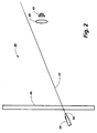
- Fig. 2 illustrates a problem with systems that do not exhibit sufficient light dispersing properties
- Fig. 3 shows a similar system that does have good light dispersing properties.
- a receiving subsystem 40 has an essentially non-diffusing screen 46, and a lens 44 and detector 42 for receiving pen location information.
- Pen 48 has a non-dispersive tip 50 which produces an effectively straight beam of light 52.
- the light tip of 50 may be, for example, a laser or an LED with an appropriate collimating lens.
- Light beam 52 goes through screen 46 in an effectively straight path from the pen tip. It can be seen in Fig. 2 that light from pen 48 never reaches lens 44 or detector 42 unless pen 48 happens to be aimed directly at lens 44.
- receiving subsystem 60 has a lens 44 and detector 42 for determining pen location information.
- screen 66 has a light diffusing surface on the front side.
- the tip 70 of pen 68 disperses light as well.
- Pen 68 is positioned towards screen 66 in the same orientation that pen 48 had to screen 46.
- Light 72 diverges as it leaves pen 70, and additionally as it passes through screen 66. Some energy from the diverged beam of light hits lens 44, which focuses a portion of the light 74 on detector 42, and enables the computer to locate the centroid of light from pen 68.
- Some LED lenses are designed to disperse light fairly widely, or the tip of the LED may be modified to diffuse the light more widely than the natural lens so that a more uniform amount of light from the pen will be scattered towards the detector at all locations on the screen and for all angles of the pen on the screen. Roughening the lens with sandpaper, for example, will cause the LED tip to disperse light more widely.
- detector 62 is a position sensing photodiode. Since, by its nature, it integrates light to produce output signals proportional to the centroid of the light spot, it is not important whether the light which reaches the detector is a very sharp image or is distributed over a large area and is relatively fuzzy. It is only the total power of the light which reaches the detector that matters, because the detector will determine the centroid of even a blurry spot.
- the subsystem of the invention is able to use a lens for gathering light that has a low imaging quality, but that has a very large aperture corresponding to about ⁇ 1 or less.
- Figs. 4 and 5 illustrate a problem with parallax that will occur with many large screen display systems unless adequate precautions are taken in the design of the light source and screen.
- Parallax describes a condition in which an apparent change in position occurs in relation to a change in line of sight. In the case of large screen displays, parallax may result in an observable difference between the location where a user observes that a light pen is positioned on the screen, and the location where the computer positions a cursor in response to where the computer detects the light pen on the screen.
- a light pen 80 is shown in writing position against a conventional screen 82.
- the conventional screen has a diffuse imaging surface 83 on one side, where the image is formed.
- the imaging surface is quite delicate, so the screen is placed with the imaging surface on the side away from the pen, with the substrate in front protecting the imaging surface from contact with the pen tip.
- the light disperses evenly and the centroid 84 of the light from pen 80 is detected by detector 86 as being located directly at the location that the user is pointing to. If the computer were producing a cursor responsive to the pen, it would be located at the centroid of the light spot and would appear to be directly at location 84, where the user is pointing.
- pen 80 is shown with the tip at the same location 85 on screen 82. However, pen 80 is in a writing position that is at a significant angle to screen 82. In normal use, it would not be unusual for a pen to be at some angle to the screen. In this case, although the user is pointing to the same physical location 84, the centroid 88 of the light spot from pen 80 is offset from location 84 by a distance d 1 . As the angle of pen 80 to the screen 82 increases, so does the offset d 1 between the physical location pointed to by the user and the centroid of the light spot 88. As a result of the long path through the substrate between location 85, where the pen touches screen 82, and the imaging surface 83, the computer system may place the cursor at a location a significant distance from the location pointed to by the user.
- Fig. 6 shows a method of reducing the parallax between the location pointed to by the user and the location recognized by the computer.
- screen 90 in accordance with an embodiment of the current invention.
- the conventional screen surface has been positioned so that the supportive substrate is located away from the user, and the imaging surface is on the forward side of the screen.
- a layer of Lucite-SAR very thin compared to the substrate material of the screen, is placed over the imaging surface 93.
- the substrate material is about 1/4 inch (0.635 cm) thick, and the Lucite-SAR layer is about 1/16 inch (0.159 cm) thick.
- the path length between the tip of the pen 80 and the imaging surface 93 is significantly reduced.
- the location of the centroid 94 where the computer will place the cursor, is offset by only a small distance d 2 .
- Fig. 7 shows a preferred embodiment of a screen 120 made according to an embodiment of the invention.
- Fig. 7(a) shows approximately a front view of the screen
- Fig. 7(b) shows a cross sectional view of the screen with an imaging layer 152 juxtaposed between a substrate 150 and a smooth, durable protective layer 154.
- Layer 150 is a backing substrate of about 1/4 inch (0.635 cm) thick acrylic plastic or Plexiglas.
- Layer 152 is an imaging surface layer made of a thin sheet of Duralene, a graphic arts drawing material manufactured by Seth Cole of Los Angeles, California.
- Duralene is an inexpensive transparent material which has good light dispersive qualities, but is quite fragile and could be easily damaged if exposed to the tip of the pen.
- Imaging layer 152 is affixed to backing layer 150 with ReMount adhesive, a product of 3M Corporation of St. Paul, Minnesota. ReMount adhesive is sprayed in a very thin layer onto the substrate, and Duralene is placed on top of it and rolled smooth and even with a rubber roller.
- Front protective layer 154 is a 1/16 inch (0.159 cm) layer of Lucite-SAR, an abrasion resistant lucite, attached to the substrate and Duralene composite by one or more (five shown) dowel pins 140. In the current embodiment, five dowel pins each 1/16 inch (0.159 cm) in diameter are pressed through the layers.
- the screen is mounted in a convex curve (as viewed) so that center front 144 is slightly forward of the two side edges 146.
- each side edge of the screen is mounted about 11 ⁇ 2 inches (3.81 cm) back of the center front.
- This stretches the front lucite layer 154 over the substrate and Duralene composite, holding the layers together tightly with a great deal of pressure. Movement between the layers of the screen, which may affect the calibration of the screen, is restricted by the pressure of the layers.
- the curved screen also provides more mechanical rigidity against flexure during writing, giving the user a firm "feel" when writing on the screen, with no additional supports that might interfere with the rear projection display image.
- the screen is constructed of DA-Glass with a DA-WA surface, coated with Protek glaze, manufactured by DaLite of Warsaw, Indiana.
- the imaging surface etched into the substrate is quite fragile and could be easily damaged if exposed to the tip of the pen.
- the substrate is positioned with the imaging surface to the front.
- a protective layer of Lucite-SAR is applied over the substrate imaging surface.
- the Lucite-SAR is secured over the DA-WA by dowel pins pressed through the two materials.
- the screen is then mounted in a convex curve (as viewed) in which the side edges of the screen are about 11 ⁇ 2 inches (3.81 cms) back of the front center of the screen.
- the screen of this embodiment may be somewhat more expensive than the previously described embodiment, but may be easier to manufacture in quantity. It also provides mechanical rigidity without additional supports which might block the rear projection display image.
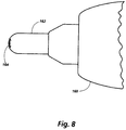
- the light pen may additionally be modified as shown in Fig. 8.
- a portion of pen 160 is shown with an LED 162 at one end.
- LEDs typically have a lens which is made of plastic which refracts the light through a restricted range.
- the tip 164 of the LED may be roughened with a fine grain sandpaper to produce a more diffused light output pattern, thus scattering a more uniform amount of light from the pen to the detector.
- Another option to protect the screen from scratches by the pen may be to spray a thin layer of a silicone lubricant, such as SLIC Silicone Lubricant, a product of Tech Spray of Amarillo, Texas, or other light spray-on lubricant, over the protective layer of the screen to reduce the friction of the pen with the screen and provide a more fluid, natural feeling writing system.
- a silicone lubricant such as SLIC Silicone Lubricant, a product of Tech Spray of Amarillo, Texas, or other light spray-on lubricant
- the lubricant is sprayed on the screen and rubbed in so that only a very light residue of lubricant is present on the screen. If the lubricant layer is too thick, the writing system will feel too "slippery" to the user.
- Fig. 9 shows a more accurate and economical large area electronic writing system according to an embodiment of the present invention.
- a large area display terminal 180 is shown in the form of a rear projection system comprising a one million pixel liquid crystal light valve panel 182, controlled by a computer (not shown) such as a SPARCStation-2 from Sun Microsystems, of Mountain View, California.
- the panel 182 is interposed between a high intensity projection lamp 184, such as a 650 watt Xenon arc lamp, focused by Fresnel lens 186, and a 270mm projection lens 188.
- the image is magnified about fivefold to illuminate, at about twenty spots per inch, a slightly convex curved (as viewed) display screen 190 having an area of about three feet (0.9144 metres) by five feet (1.524 metres).
- One or more wireless light pens 200 project a beam of light from a light source 202, such as a Siemens SFH485 5mm diameter, 8mm long LED, onto the front surface of the screen 190 at a location where the user desires to indicate input, such as locating a pointer.
- a light source 202 such as a Siemens SFH485 5mm diameter, 8mm long LED
- the tip of the LED is roughened with fine grain sandpaper, as described in relation to Fig. 8, to increase the scattering of light by the light source. It would be practical to maintain the light pen in contact with the surface being written upon, or to project the light spot from several feet away from the screen. It should be noted that as a remote pen projects a larger light spot, the effective zone of accurate usage gets closer to the center of the screen because too much light falls off the screen.
- the tip of the light pen should not disperse light so broadly that the position of the light spot does not change in relation to a change in the angle of a remote pen.
- the roughened surface as described in relation to Fig. 8, produces enough light dispersion to reduce intensity variations with the position and angle of the pen when the pen is touching the screen, without significantly degrading the ability of the system to detect changes in the position of the pen when held remotely.
- the user's feedback is generated by the electronic system and presented on the display in response to the information obtained by the receiving subsystem.
- the feedback may take the form of an indicator or cursor located at the pixel location corresponding to the location pointed to by the light pen.
- a large curvature demagnification lens 194 such as a Melles-Griot aspheric condenser lens #01-LAG-115, aperture 32.5, focal length 23.5 and ⁇ 0.72, directs the light spot from the user's light pen through a filter 196 which blocks out spurious light and then focuses the spot upon a position sensing photodiode 198.
- Position sensing photodiode 198 such as UDT SC25D quadrant detector, from United Detector Technology of Hawthorne, California, is a continuous dual axis position sensor that provides both x and y axis position information. It senses the centroid of a light spot and provides continuous analog outputs as the spot traverses the active area.
- An input device for such a large area writing system may alternatively include a light pen in which bundled optic fibers, of either glass or plastic, are coupled to the light source and provided at the tip. Such a fiber optic tip may provide a "feel" more similar to the feel of a felt tip pen against a conventional whiteboard.
- Such a fiber optic pen may have a laser light source coupled to the optic fibers which would be able to efficiently convert electrical energy from the battery source into light energy.
- the optic fibers may naturally diverge the light at the pen tip, or may be appropriately formed to diverge the light at the pen tip.
Landscapes
- Engineering & Computer Science (AREA)
- General Engineering & Computer Science (AREA)
- Theoretical Computer Science (AREA)
- Human Computer Interaction (AREA)
- Physics & Mathematics (AREA)
- General Physics & Mathematics (AREA)
- Multimedia (AREA)
- Position Input By Displaying (AREA)
- Drawing Aids And Blackboards (AREA)
Claims (8)
- Elektronisches Schreibsystem, mit:einem parallaxenreduzierenden Anzeigeschirm (190) mit einer lichtstreuenden Bildoberfläche,einer Projektionseinrichtung (200, 202) zum Projizieren eines modifizierbaren Lichtpunktes, der eine Eingabelokations-lnformation auf der Seite der Bildoberfläche wiedergibt,einer Sensoreinrichtung (194, 198) zum Abfühlen des Lichtpunkts und zum Erzeugen von Ausgabesignalen, die die Eingabelokations-lnformation wiedergeben, wobei die Sensoreinrichtung (194, 198) auf einer zweiten Seite der Bildoberfläche angeordnet ist, undeiner Rückprojektionseinrichtung (188) zum Anzeigen von Information auf der zweiten Seite des Bildoberfläche, wobei die angezeigte Information eine genaue Pixellokation angibt, die der durch den Lichtpunkt eingegebenen Lokations-Information entspricht, dadurch gekennzeichnet, daß die Sensoreinrichtung (194, 198) eine Bildlinse (194) mit einer großen Öffnung und einen integrierten Positionsdetektor (198) umfaßt.
- Elektronisches Schreibsystem nach Anspruch 1, wobei der parallaxenreduzierende Anzeigeschirm (190) weiterhin umfaßt:eine Schicht aus einem steifen, transparenten Substrat (150),und eine Schutzschicht (154), die wesentlich dünner ist als die Substratschicht (150), wobei die Parallaxe reduziert wird, wenn die Lichtpunktquelle in Kontakt mit der Schutzschicht ist,wobei die Bildoberfläche zwischen dem Substrat (150) und der Schutzschicht (154) angeordnet ist, wobei der Anzeigeschirm (190) derart angeordnet ist, daß eine Seite der Schutzschicht (154) unmittelbar neben der einen Seite des Bildoberfläche angeordnet ist.
- Elektronisches Schreibsystem nach Anspruch 2, wobei der Anzeigeschirm (190) weiterhin auf der zweiten Seite der Schutzschicht (154) eine dünne Schicht aus Schmiermittel umfaßt:
- Elektronisches Schreibsystem nach wenigstens einem der Ansprüche 1 bis 3, wobei die Projektionseinrichtung (100, 202) eine lichtemittierende Diode mit einer gerauhten Oberfläche an der Spitze umfaßt.
- Elektronisches Schreibsystem nach wenigstens einem der Ansprüche 1 bis 4, wobei die Bildlinse eine Öffnung von f1,0 oder weniger aufweist.
- Elektronisches Schreibsystem nach wenigstens einem der Ansprüche 1 bis 5, wobei die Bildlinse (194) mit der großen Öffnung derart angeordnet ist, daß sie Energie von im wesentlichen der gesamten Bildoberfläche auf den integrierten Positionsdetektor (198) fokussiert.
- Elektronisches Schreibsystem nach wenigstens einem der Ansprüche 1 bis 6, wobei die Bildoberfläche aus einer Schicht aus einem transparenten lichtstreuenden Material besteht.
- Elektronisches Schreibsystem nach wenigstens einem der Ansprüche 2 bis 6, wobei die Bildoberfläche eine geätzte Oberfläche auf der Substratschicht (150) auf der Seite der Schutzschicht (154) ist.
Applications Claiming Priority (2)
| Application Number | Priority Date | Filing Date | Title |
|---|---|---|---|
| US863650 | 1992-04-03 | ||
| US07/863,650 US5495269A (en) | 1992-04-03 | 1992-04-03 | Large area electronic writing system |
Publications (3)
| Publication Number | Publication Date |
|---|---|
| EP0564200A2 EP0564200A2 (de) | 1993-10-06 |
| EP0564200A3 EP0564200A3 (de) | 1993-10-27 |
| EP0564200B1 true EP0564200B1 (de) | 1998-07-01 |
Family
ID=25341493
Family Applications (1)
| Application Number | Title | Priority Date | Filing Date |
|---|---|---|---|
| EP93302409A Expired - Lifetime EP0564200B1 (de) | 1992-04-03 | 1993-03-26 | Elektronisches Schreibsystem |
Country Status (4)
| Country | Link |
|---|---|
| US (1) | US5495269A (de) |
| EP (1) | EP0564200B1 (de) |
| JP (1) | JP3067452B2 (de) |
| DE (1) | DE69319364T2 (de) |
Families Citing this family (58)
| Publication number | Priority date | Publication date | Assignee | Title |
|---|---|---|---|---|
| US7098891B1 (en) * | 1992-09-18 | 2006-08-29 | Pryor Timothy R | Method for providing human input to a computer |
| US9513744B2 (en) * | 1994-08-15 | 2016-12-06 | Apple Inc. | Control systems employing novel physical controls and touch screens |
| JP3006448B2 (ja) * | 1995-02-09 | 2000-02-07 | 富士ゼロックス株式会社 | 情報入出力システム |
| US20090273574A1 (en) * | 1995-06-29 | 2009-11-05 | Pryor Timothy R | Programmable tactile touch screen displays and man-machine interfaces for improved vehicle instrumentation and telematics |
| US7973773B2 (en) * | 1995-06-29 | 2011-07-05 | Pryor Timothy R | Multipoint, virtual control, and force based touch screen applications |
| US8228305B2 (en) * | 1995-06-29 | 2012-07-24 | Apple Inc. | Method for providing human input to a computer |
| IL119259A (en) * | 1996-09-17 | 2000-12-06 | Comview Graphics Ltd | Electro-optical display apparatus and method of using same |
| US5764224A (en) * | 1997-03-25 | 1998-06-09 | Ericsson Inc. | Cordless mouse-stylus-pointer |
| JP3876942B2 (ja) * | 1997-06-13 | 2007-02-07 | 株式会社ワコム | 光デジタイザ |
| JP2002503892A (ja) * | 1997-09-17 | 2002-02-05 | コムヴュー グラフィックス リミテッド | 電気光学表示装置 |
| GB9722766D0 (en) | 1997-10-28 | 1997-12-24 | British Telecomm | Portable computers |
| US8479122B2 (en) * | 2004-07-30 | 2013-07-02 | Apple Inc. | Gestures for touch sensitive input devices |
| US7614008B2 (en) * | 2004-07-30 | 2009-11-03 | Apple Inc. | Operation of a computer with touch screen interface |
| US9292111B2 (en) | 1998-01-26 | 2016-03-22 | Apple Inc. | Gesturing with a multipoint sensing device |
| US9239673B2 (en) | 1998-01-26 | 2016-01-19 | Apple Inc. | Gesturing with a multipoint sensing device |
| US6396005B2 (en) | 1998-06-15 | 2002-05-28 | Rodgers Technology Center, Inc. | Method and apparatus for diminishing grid complexity in a tablet |
| US6664954B1 (en) * | 1998-11-05 | 2003-12-16 | Canon Kabushiki Kaisha | Coordinate input indicator |
| EP1141815B1 (de) * | 1999-01-13 | 2003-03-12 | TDS CAD Graphics Limited | Interaktives anzeigesystem |
| US6545670B1 (en) * | 1999-05-11 | 2003-04-08 | Timothy R. Pryor | Methods and apparatus for man machine interfaces and related activity |
| US8482535B2 (en) * | 1999-11-08 | 2013-07-09 | Apple Inc. | Programmable tactile touch screen displays and man-machine interfaces for improved vehicle instrumentation and telematics |
| US20010032057A1 (en) * | 1999-12-23 | 2001-10-18 | Smith Randall G. | Initial calibration of a location sensing whiteboard to a projected display |
| US6828956B2 (en) * | 2000-01-26 | 2004-12-07 | Canon Kabushiki Kaisha | Coordinate input apparatus, coordinate input system, coordinate input method, and pointer |
| US20080122799A1 (en) * | 2001-02-22 | 2008-05-29 | Pryor Timothy R | Human interfaces for vehicles, homes, and other applications |
| US8576199B1 (en) | 2000-02-22 | 2013-11-05 | Apple Inc. | Computer control systems |
| US20080088587A1 (en) * | 2001-02-22 | 2008-04-17 | Timothy Pryor | Compact rtd instrument panels and computer interfaces |
| US20080024463A1 (en) * | 2001-02-22 | 2008-01-31 | Timothy Pryor | Reconfigurable tactile control display applications |
| JP2003108305A (ja) * | 2001-09-28 | 2003-04-11 | Fuji Photo Optical Co Ltd | プレゼンテーションシステム |
| US6803907B2 (en) * | 2001-10-04 | 2004-10-12 | Inventec Corporation | Wireless beam-pen pointing device |
| US7224347B2 (en) * | 2002-05-09 | 2007-05-29 | Hewlett-Packard Development Company, L.P. | Writeboard method and apparatus |
| US7358963B2 (en) | 2002-09-09 | 2008-04-15 | Apple Inc. | Mouse having an optically-based scrolling feature |
| JP4555777B2 (ja) * | 2003-07-03 | 2010-10-06 | 株式会社きもと | 透過型スクリーン |
| US7496626B2 (en) * | 2003-12-10 | 2009-02-24 | International Business Machines Corporation | System and method for role pen based messaging in a synchronous collaborative environment |
| RU2247406C1 (ru) * | 2004-02-10 | 2005-02-27 | Закрытое акционерное общество "НПО Космического Приборостроения" | Способ повышения радиуса действия кинематического режима реального времени определения относительных координат объекта |
| US20050203999A1 (en) * | 2004-03-11 | 2005-09-15 | International Business Machines Corporation | System and method for rule-pen based conversations in synchronous collaborative environment |
| US20080129707A1 (en) * | 2004-07-27 | 2008-06-05 | Pryor Timothy R | Method and apparatus employing multi-functional controls and displays |
| US8381135B2 (en) | 2004-07-30 | 2013-02-19 | Apple Inc. | Proximity detector in handheld device |
| US20100231506A1 (en) * | 2004-09-07 | 2010-09-16 | Timothy Pryor | Control of appliances, kitchen and home |
| US7898505B2 (en) * | 2004-12-02 | 2011-03-01 | Hewlett-Packard Development Company, L.P. | Display system |
| US8077147B2 (en) * | 2005-12-30 | 2011-12-13 | Apple Inc. | Mouse with optical sensing surface |
| JP2008146463A (ja) * | 2006-12-12 | 2008-06-26 | Mitsubishi Electric Corp | 位置検出装置 |
| US7844915B2 (en) | 2007-01-07 | 2010-11-30 | Apple Inc. | Application programming interfaces for scrolling operations |
| EP2144189A3 (de) * | 2008-07-10 | 2014-03-05 | Samsung Electronics Co., Ltd. | Verfahren zum Erkennen und Umwandeln von Buchstaben in kamerabasierten Bildern |
| US20100031152A1 (en) * | 2008-07-31 | 2010-02-04 | Microsoft Corporation | Creation and Navigation of Infinite Canvas Presentation |
| US8108777B2 (en) | 2008-08-11 | 2012-01-31 | Microsoft Corporation | Sections of a presentation having user-definable properties |
| EP2194447A1 (de) * | 2008-12-08 | 2010-06-09 | IBBT vzw | Elektronisches Streichsystem und Gerät zur Eingabe in diesem System |
| US10127524B2 (en) * | 2009-05-26 | 2018-11-13 | Microsoft Technology Licensing, Llc | Shared collaboration canvas |
| US20110242005A1 (en) * | 2010-03-31 | 2011-10-06 | Smart Technologies Ulc | Interactive input device with palm reject capabilities |
| US20110246875A1 (en) * | 2010-04-02 | 2011-10-06 | Symantec Corporation | Digital whiteboard implementation |
| US9118612B2 (en) | 2010-12-15 | 2015-08-25 | Microsoft Technology Licensing, Llc | Meeting-specific state indicators |
| US9383888B2 (en) | 2010-12-15 | 2016-07-05 | Microsoft Technology Licensing, Llc | Optimized joint document review |
| US9864612B2 (en) | 2010-12-23 | 2018-01-09 | Microsoft Technology Licensing, Llc | Techniques to customize a user interface for different displays |
| DE102011101451A1 (de) * | 2011-04-20 | 2012-10-25 | Conen Produkte Gmbh & Co. Kg | Verfahren zum Umbau einer mit Kreide beschreibbaren Tafel in ein interaktives Tafelsystem |
| US8682973B2 (en) | 2011-10-05 | 2014-03-25 | Microsoft Corporation | Multi-user and multi-device collaboration |
| US9544158B2 (en) * | 2011-10-05 | 2017-01-10 | Microsoft Technology Licensing, Llc | Workspace collaboration via a wall-type computing device |
| US9996241B2 (en) | 2011-10-11 | 2018-06-12 | Microsoft Technology Licensing, Llc | Interactive visualization of multiple software functionality content items |
| US10198485B2 (en) | 2011-10-13 | 2019-02-05 | Microsoft Technology Licensing, Llc | Authoring of data visualizations and maps |
| US9707491B2 (en) | 2011-10-19 | 2017-07-18 | Randy Wayne Clark | Light activated glow-in-the-dark doodler |
| WO2013106801A1 (en) | 2012-01-13 | 2013-07-18 | Clark Randy Wayne | Light emitting toys and light activated targets |
Family Cites Families (12)
| Publication number | Priority date | Publication date | Assignee | Title |
|---|---|---|---|---|
| US3539717A (en) * | 1967-09-25 | 1970-11-10 | Texas Instruments Inc | Touch control display system |
| JPS5726369B2 (de) * | 1973-09-06 | 1982-06-04 | ||
| US4089587A (en) * | 1974-11-29 | 1978-05-16 | Schudel Conrad R | Projection screen surface and method of forming said surface |
| US4164081A (en) * | 1977-11-10 | 1979-08-14 | The United States Of America As Represented By The Secretary Of The Navy | Remote target hit monitoring system |
| US4565999A (en) * | 1983-04-01 | 1986-01-21 | Prime Computer, Inc. | Light pencil |
| JPS60230228A (ja) * | 1984-04-28 | 1985-11-15 | Mitsubishi Electric Corp | 投射型画像再生装置の画面位置指定方式 |
| EP0281436A1 (de) * | 1987-02-12 | 1988-09-07 | Martine Harraca-Roehl | Zusammengesetzte Schicht und aus dieser Schicht hergestellte Bildschirme |
| US4873398A (en) * | 1988-06-30 | 1989-10-10 | Hewlett-Packard Company | Flat panel display with integrated digitizing tablet |
| ES2067032T3 (es) * | 1989-07-19 | 1995-03-16 | Bell Communications Res | Sistema de lapiz luminoso para imagenes proyectadas. |
| FR2657701B1 (fr) * | 1990-01-31 | 1993-07-02 | Saksik Claude | Methode de projection et visualisation des images des deux cotes d'un ecran special. |
| US5025314A (en) * | 1990-07-30 | 1991-06-18 | Xerox Corporation | Apparatus allowing remote interactive use of a plurality of writing surfaces |
| CA2051204C (en) * | 1990-11-02 | 1999-04-20 | Scott A. Elrod | Position and function input system for a large area display |
-
1992
- 1992-04-03 US US07/863,650 patent/US5495269A/en not_active Expired - Lifetime
-
1993
- 1993-03-26 EP EP93302409A patent/EP0564200B1/de not_active Expired - Lifetime
- 1993-03-26 DE DE69319364T patent/DE69319364T2/de not_active Expired - Lifetime
- 1993-03-29 JP JP7047093A patent/JP3067452B2/ja not_active Expired - Lifetime
Also Published As
| Publication number | Publication date |
|---|---|
| US5495269A (en) | 1996-02-27 |
| DE69319364T2 (de) | 1998-12-17 |
| JPH0612182A (ja) | 1994-01-21 |
| EP0564200A3 (de) | 1993-10-27 |
| DE69319364D1 (de) | 1998-08-06 |
| JP3067452B2 (ja) | 2000-07-17 |
| EP0564200A2 (de) | 1993-10-06 |
Similar Documents
| Publication | Publication Date | Title |
|---|---|---|
| EP0564200B1 (de) | Elektronisches Schreibsystem | |
| CN102144208B (zh) | 结合笔跟踪的多点触摸触摸屏 | |
| EP0786107B1 (de) | Lichtstifteingabesysteme | |
| US8842076B2 (en) | Multi-touch touchscreen incorporating pen tracking | |
| AU2010218345B2 (en) | Dynamic rear-projected user interface | |
| US5317140A (en) | Diffusion-assisted position location particularly for visual pen detection | |
| KR100349031B1 (ko) | 펜형 광 마우스 장치 | |
| US20060290684A1 (en) | Coordinate detection system for a display monitor | |
| JP3530758B2 (ja) | 座標入力用指示具 | |
| US20100103103A1 (en) | Method And Device for Input Of Information Using Visible Touch Sensors | |
| US20080192017A1 (en) | Automatic Projection Calibration | |
| US20150015545A1 (en) | Pointing input system having sheet-like light beam layer | |
| KR20030036979A (ko) | 펜형 광 마우스 장치 및 펜형 광 마우스 장치의 제어방법 | |
| KR20230043663A (ko) | 멀티 id 터치펜 속성 입력 ui를 적용한 인터랙티브 화이트 보드 | |
| KR20010016506A (ko) | 광 마우스 장치 | |
| KR102544258B1 (ko) | 터치감을 향상시킨 인터랙티브 화이트 보드 | |
| EP3455707B1 (de) | Berührungstafel | |
| KR20080031159A (ko) | 자동 프로젝션 조정 | |
| US8786544B1 (en) | Low RSI absolute coordinate mouse using optical three-dimensional sensing with mouse click functions |
Legal Events
| Date | Code | Title | Description |
|---|---|---|---|
| PUAI | Public reference made under article 153(3) epc to a published international application that has entered the european phase |
Free format text: ORIGINAL CODE: 0009012 |
|
| PUAL | Search report despatched |
Free format text: ORIGINAL CODE: 0009013 |
|
| AK | Designated contracting states |
Kind code of ref document: A2 Designated state(s): DE FR GB |
|
| AK | Designated contracting states |
Kind code of ref document: A3 Designated state(s): DE FR GB |
|
| 17P | Request for examination filed |
Effective date: 19940412 |
|
| 17Q | First examination report despatched |
Effective date: 19970226 |
|
| GRAG | Despatch of communication of intention to grant |
Free format text: ORIGINAL CODE: EPIDOS AGRA |
|
| GRAG | Despatch of communication of intention to grant |
Free format text: ORIGINAL CODE: EPIDOS AGRA |
|
| GRAH | Despatch of communication of intention to grant a patent |
Free format text: ORIGINAL CODE: EPIDOS IGRA |
|
| GRAH | Despatch of communication of intention to grant a patent |
Free format text: ORIGINAL CODE: EPIDOS IGRA |
|
| GRAA | (expected) grant |
Free format text: ORIGINAL CODE: 0009210 |
|
| AK | Designated contracting states |
Kind code of ref document: B1 Designated state(s): DE FR GB |
|
| REF | Corresponds to: |
Ref document number: 69319364 Country of ref document: DE Date of ref document: 19980806 |
|
| ET | Fr: translation filed | ||
| PLBE | No opposition filed within time limit |
Free format text: ORIGINAL CODE: 0009261 |
|
| STAA | Information on the status of an ep patent application or granted ep patent |
Free format text: STATUS: NO OPPOSITION FILED WITHIN TIME LIMIT |
|
| 26N | No opposition filed | ||
| REG | Reference to a national code |
Ref country code: GB Ref legal event code: IF02 |
|
| PGFP | Annual fee paid to national office [announced via postgrant information from national office to epo] |
Ref country code: FR Payment date: 20120319 Year of fee payment: 20 |
|
| PGFP | Annual fee paid to national office [announced via postgrant information from national office to epo] |
Ref country code: GB Payment date: 20120321 Year of fee payment: 20 |
|
| PGFP | Annual fee paid to national office [announced via postgrant information from national office to epo] |
Ref country code: DE Payment date: 20120411 Year of fee payment: 20 |
|
| REG | Reference to a national code |
Ref country code: DE Ref legal event code: R071 Ref document number: 69319364 Country of ref document: DE |
|
| REG | Reference to a national code |
Ref country code: GB Ref legal event code: PE20 Expiry date: 20130325 |
|
| PG25 | Lapsed in a contracting state [announced via postgrant information from national office to epo] |
Ref country code: GB Free format text: LAPSE BECAUSE OF EXPIRATION OF PROTECTION Effective date: 20130325 Ref country code: DE Free format text: LAPSE BECAUSE OF EXPIRATION OF PROTECTION Effective date: 20130327 |