EP0564221B1 - Transmission de puissance rotative - Google Patents
Transmission de puissance rotative Download PDFInfo
- Publication number
- EP0564221B1 EP0564221B1 EP93302452A EP93302452A EP0564221B1 EP 0564221 B1 EP0564221 B1 EP 0564221B1 EP 93302452 A EP93302452 A EP 93302452A EP 93302452 A EP93302452 A EP 93302452A EP 0564221 B1 EP0564221 B1 EP 0564221B1
- Authority
- EP
- European Patent Office
- Prior art keywords
- source
- rotary
- load
- rotary power
- wheel
- Prior art date
- Legal status (The legal status is an assumption and is not a legal conclusion. Google has not performed a legal analysis and makes no representation as to the accuracy of the status listed.)
- Expired - Lifetime
Links
- 230000005540 biological transmission Effects 0.000 claims description 68
- 230000007935 neutral effect Effects 0.000 claims description 18
- 238000000034 method Methods 0.000 claims description 15
- 230000033001 locomotion Effects 0.000 claims description 6
- 230000000694 effects Effects 0.000 claims description 5
- 238000009434 installation Methods 0.000 claims description 5
- 238000002485 combustion reaction Methods 0.000 description 9
- NJPPVKZQTLUDBO-UHFFFAOYSA-N novaluron Chemical compound C1=C(Cl)C(OC(F)(F)C(OC(F)(F)F)F)=CC=C1NC(=O)NC(=O)C1=C(F)C=CC=C1F NJPPVKZQTLUDBO-UHFFFAOYSA-N 0.000 description 6
- 238000010276 construction Methods 0.000 description 2
- 238000007747 plating Methods 0.000 description 1
Images


Classifications
-
- F—MECHANICAL ENGINEERING; LIGHTING; HEATING; WEAPONS; BLASTING
- F16—ENGINEERING ELEMENTS AND UNITS; GENERAL MEASURES FOR PRODUCING AND MAINTAINING EFFECTIVE FUNCTIONING OF MACHINES OR INSTALLATIONS; THERMAL INSULATION IN GENERAL
- F16H—GEARING
- F16H7/00—Gearings for conveying rotary motion by endless flexible members
- F16H7/08—Means for varying tension of belts, ropes or chains
- F16H7/0827—Means for varying tension of belts, ropes or chains for disconnecting the drive
-
- F—MECHANICAL ENGINEERING; LIGHTING; HEATING; WEAPONS; BLASTING
- F16—ENGINEERING ELEMENTS AND UNITS; GENERAL MEASURES FOR PRODUCING AND MAINTAINING EFFECTIVE FUNCTIONING OF MACHINES OR INSTALLATIONS; THERMAL INSULATION IN GENERAL
- F16H—GEARING
- F16H7/00—Gearings for conveying rotary motion by endless flexible members
- F16H7/02—Gearings for conveying rotary motion by endless flexible members with belts; with V-belts
-
- F—MECHANICAL ENGINEERING; LIGHTING; HEATING; WEAPONS; BLASTING
- F16—ENGINEERING ELEMENTS AND UNITS; GENERAL MEASURES FOR PRODUCING AND MAINTAINING EFFECTIVE FUNCTIONING OF MACHINES OR INSTALLATIONS; THERMAL INSULATION IN GENERAL
- F16H—GEARING
- F16H7/00—Gearings for conveying rotary motion by endless flexible members
- F16H7/08—Means for varying tension of belts, ropes or chains
- F16H7/10—Means for varying tension of belts, ropes or chains by adjusting the axis of a pulley
- F16H7/12—Means for varying tension of belts, ropes or chains by adjusting the axis of a pulley of an idle pulley
Definitions
- THIS INVENTION relates to transmitting rotary power. It relates more specifically to a method of transmitting rotary power, to a rotary power transmission device and to an installation in which rotary power is transmitted from a source of rotary power to a rotary load.
- This invention will find particular application in the field of power transmission in low speed, low power, motorized vehicles and also stationary applications. " The invention is, however, not limited to those fields.
- a method of transmitting rotary power, from a source of rotary power to a rotary load, selectively in at least two drive modes including the steps as defined in claim 1 whereby the measures outlined in the preamble thereof are known from US-A-4 696 661.
- the method may include interrupting transmission of power from the source of rotary power to the rotary load in a neutral mode by moving the casing into a neutral condition.
- Moving the transmission device may preferably be by pivoting, the transmission device being pivotally mounted.
- the first and second operative conditions will then correspond to different angular orientations of the transmission device.
- the neutral condition may be intermediate the first and second operative conditions.
- connecting of the rotary load by means of the load connection means to the transmission device may be fixed, connecting of the source of rotary power by means of the source connection means to the transmission device then being adapted appropriately to effect driving connection and to disconnect drive in response to the condition of the transmission device.
- Connecting the rotary load to the transmission device may then include connecting the rotary load in accordance with the first drive mode to the first intermediate wheel, and connecting the rotary load in accordance with the second drive mode to the second intermediate wheel.
- the method may further include transmitting the rotary power frictionally via the source connection means by means of flexible, endless drive members.
- Said one class of methods may further include transmitting the rotary power from the respective intermediate wheels to the rotary load by means of auxiliary first and second intermediate wheels fixed to the first and second intermediate wheels and via an output wheel drivingly connected to the auxiliary first and second wheels and to the rotary load.
- the invention extends also to a rotary power transmission device, suitable for transmitting rotary power, from a source of rotary power to a rotary load, selectively in at least two drive modes, the transmission device including the features as defined in claim 8 whereby the features of the preamble thereof are known from US-A-4 696 661.
- the mounting means may allow moving of the casing as a whole into a neutral position corresponding to a neutral condition of the transmission device in which transmission of power is interrupted.
- the neutral position may be a position of the casing as a whole intermediate positions of the casing as a whole corresponding respectively to the first and second operative conditions.
- the mounting means may be pivotal mounting means such that the casing as a whole is pivotal between its first and second operative positions.
- the mounting means may be adapted to mount the casing for movement as a whole relative to the source of rotary power, the load connection means being adapted fixedly to connect the rotary load to the first and second intermediate wheels, and the source connection means being adapted appropriately to effect driving connection and to disconnect drive in response to the position of the casing as a whole.
- the pivotal mounting of the casing as a whole may be about an axis co-axial with an axis of an output shaft driving into the rotary load in use.
- the line or distance from said axis of the output shaft to any point on the casing - specifically to the first and second intermediate wheels - then remains constant regardless of the angular orientation of the casing.
- the first and second intermediate wheels may be in the form of pulleys, driving connection between the source of rotary power and the respective intermediate wheels being frictional to transmit full power by means of belts.
- the load connection means may include an auxiliary first intermediate and an auxiliary second intermediate wheel which are respectively drivingly connected such as to receive full power from the first and second intermediate wheels, an output wheel, and output connection means drivingly connecting the output wheel to the auxiliary first and auxiliary second intermediate wheels such as to transmit full power.
- the first intermediate wheel and first auxiliary intermediate wheel may fixedly drivingly be connected about a common axis and the second intermediate wheel and second auxiliary intermediate wheel may fixedly drivingly be connected about a common axis.
- the auxiliary intermediate wheels and the output wheel may be in the form of pulleys, the output connection means being in the form of complemental V-belts adapted to transmit full power.
- auxiliary intermediate wheels and the output wheel may be in the form of sprockets, the output connection means being in the form of a complemental chain adapted to transmit full power.
- the auxiliary intermediate wheels and the output wheel may be in the form of cogged wheels, the output connection means being provided by an arrangement causing the cogged wheels to mesh such as to transmit full power.
- a suitable combination of, say, chain drive and cogged wheel or gear drive may be used instead.
- the auxiliary intermediate wheels and output wheel are in the form of pulleys and the output connection means is in the form of complemental V-belts
- the auxiliary intermediate wheels may be in the form of adjustable pulleys to allow the relative diameters of the pulleys to be adjusted to effect speed adjustment.
- the auxiliary intermediate wheels may be in the form of stepped pulleys to allow different speed ratios to be selected.
- the intermediate wheels, rather than the auxiliary intermediate wheels may be in the form of adjustable pulleys or stepped pulleys. Then, it may be possible to accommodate the length discrepancy in the belt length by appropriately changing the working angle or attitude of the pivoting mechanism.
- the invention extends yet further to an installation including a source of rotary power, a rotary load and a transmission device as herein described, the components being operatively connected to transmit rotary power from the source of rotary power to the rotary load.
- the installation may be in the form of a motorized vehicle, a drive wheel of the vehicle forming the rotary load.
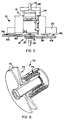
- a motor/transmission unit in accordance with the invention is generally indicated by reference numeral 10. It comprises an internal combustion engine generally indicated by reference numeral 12, a transmission device in accordance with the invention and indicated by reference numeral 14 and an output shaft 16 representing a rotary load. In practice, a rotary load will drivingly be connected to the output shaft 16.
- the transmission device 14 is arranged to transmit rotary power selectively in two modes to the output shaft 16.
- the internal combustion engine 12 has an output shaft 18 on which are mounted two drive pulleys respectively indicated by reference numerals 20 and 22.
- the internal combustion engine 12 is supported at an elevated position on a pedestal 24 which is mounted on a bed plate 26.
- the pedestal 24 is in the form of appropriately bent plating.
- the output shaft 16 is mounted for rotation in bearings 17 in the pedestal 24.
- the output shaft 16 is parallel to, and in this case vertically underneath, the output shaft 18 of the internal combustion engine 12.
- the output shaft 16 extends rearwardly beyond the pedestal 24 to allow a rotary load to be connected thereto from the rear. It also extends forwardly well beyond the front of the pedestal 24 to mount the transmission device 14 as will be described hereinafter and also to provide a fore extension to which a rotary load can be connected.
- the transmission device 14 comprises a hollow pivotal casing 30 which is mounted by means of bearings 32, such as to allow pivoting, on the output shaft 16 immediately in front of the pedestal 24.
- a pivot member 38 fast with the pivotal casing 30 mounts a pivot shaft 40 by means of which the pivotal casing 30 can be pivoted pendulum fashion generally as indicated by reference numeral 36 in Figure 1.
- an output wheel 42 such as to be drivingly connected to the output 16. It is of significance that the pivotal casing 30 is pivotal about the axis of the output wheel 42.
- a first intermediate wheel 44 is mounted for rotation on the pivotal casing 30 to be aligned with the first drive pulley 20.
- the first intermediate wheel 44 is mounted via a stub shaft in bearings mounted on the pivotal casing generally as indicated by reference numeral 46.
- the stub shaft has an axis which is parallel to the output shaft 16 and transversely spaced therefrom toward one side of the transmission device 14.
- a second intermediate wheel 54 toward an opposed side of the pivotal casing 30 there is provided a second intermediate wheel 54 toward an opposed side of the pivotal casing 30. Also the second intermediate wheel 54 is mounted by way of a stub shaft and bearings generally as indicated by reference numeral 56 to the pivotal casing 30. A second auxiliary intermediate wheel 58 is provided fast with the stub shaft internal of the pivotal casing 30 and in line with the output wheel 42.
- the first intermediate wheel 44 is aligned with the first drive pulley 20 and is drivingly connected by means of a V-belt 50 with the first drive pulley 20.
- the first intermediate wheel 44 is also in the form of a pulley.
- the second intermediate wheel 54 is aligned with the second drive pulley 22 and is connected thereby by means of a V-belt 60.
- the second intermediate wheel 54 is in the form of a pulley.
- the first and second auxiliary intermediate wheels 48 and 58 are aligned with each other and with the output wheel 42.
- a drive element 51 drivingly connects both of the auxiliary intermediate wheels 48 and 58 to the output wheel 42.
- Driving interconnection is such that, when the first intermediate wheel 44 rotates counter-clockwise as seen in Figure 1, the output wheel 42 will rotate clockwise. In contrast, if the second intermediate wheel 54 is rotated counter-clockwise, the output wheel 42 will also be rotated counter-clockwise.
- separate output wheels which may or may not be mounted on a common shaft, may be provided. Separate driving connections to the auxiliary intermediate wheels will then be provided.
- the pivotal casing 30 is pivoted in a desired direction 36 such that a desired one of the V-belts 50 and 60 is drivingly connected via its drive pulley 20 or 22 to the output shaft 18 of the internal combustion engine 12.
- the other of the intermediate wheels is drivingly disconnected from its output pulley as its V-belt is slack.
- neither of the V-belts 50, 60 is connected, and no drive is transmitted, as both V-belts are slack.
- guides 45/55 are provided spaced around lower portions of the first and second intermediate wheels 44, 54 to cover the V-belts 50, 60 and furthermore, when any of the V-belts 50, 60 is slackened, to lift such V-belt with lost motion such that it unseats from its drive pulley 20, 22.
- the V-belt which is not tensioned and which is thus not operative is lifted off its pulleys or at least partially off its pulleys such that it is not connected.
- guides 21/23 are provided around the upper portions of the drive pulleys 20, 22 to receive the respective V-belts with lost motion when lifted from the pulleys 20, 22.
- the guides 21/23 are mounted on a side plate 25 behind the pulleys 20/22.
- the guides 45/55 are mounted on a side plate 57 behind the pulleys 44/54.
- the guides and side plates are shown in Figure 1 only. For clarity of drawing, they have been omitted from the other figures.
- V-belt 50/60 is then transmitted from the internal combustion engine 12 via the tensioned V-belt 50/60 to the appropriate intermediate wheel 44/54 and thence from the corresponding auxiliary intermediate wheel 48/58 via the drive element 51 to the output wheel 42 and the output shaft 16.
- Tensioner wheels 52 keep the drive element 51 under tension.
- the transmission device 114 makes use of a chain drive between its auxiliary intermediate wheels 148, 158 and the output wheel 142.
- the first and second auxiliary intermediate wheels 148, 158 and output wheel 142 are in the form of cogged wheels.
- the drive element 151 is in the form of a chain.
- the arrangement of the chain 151 is such that the direction of drive remains the same regardless of whether drive takes place via the first intermediate wheel 54 or the second intermediate wheel 44.
- the second auxiliary intermediate wheel 158 is smaller than the corresponding first auxiliary intermediate wheel 148.
- the two modes at which drive can be transmitted differ in respect of speed ratio.
- the transmission device 214 is similar to the transmission device 114 in that a chain drive is used. However, it is similar to the device of Figure 1 in that drive is transmitted at equal speed ratios but in opposite directions of rotation.
- auxiliary intermediate wheels and the output wheel in each case, are in the form of gears which are drivingly interconnected by meshing with one another.
- the direction of rotation is the same regardless of whether drive takes place via the first intermediate wheel 44 or the second intermediate wheel 54.
- the second auxiliary intermediate wheel 358 is larger than the first auxiliary intermediate wheel 348 and the speed ratio at which power is transmitted via the second intermediate wheel 54 is higher than via the first intermediate wheel 44.
- meshing between the first auxiliary intermediate wheel 448 and the output wheel 442 is via an idler gear 452 and thus the direction of transmission is reversed depending on whether it takes place via the first intermediate wheel 44 or the second intermediate wheel 54.
- the diameter ratio of the first auxiliary intermediate wheel 448 and the second auxiliary intermediate wheel 458 is about 1:2 or 1:3 and there is thus a substantial difference in the speed ratios.
- an adjustable pulley assembly used preferably in pairs, may be utilized.
- a pulley assembly is generally indicated by reference numeral 70 in Figure 8.
- the assembly 70 comprises an adjustable pulley 72 having flanges 74 the spacing of which is varied to adjust the effective diameter at which a V-belt engages the pulley and thus effectively varying the speed of transmission. It has adjustment means generally indicated by reference numeral 76 by means of which the spacing of the flanges 74 can be adjusted.
- the adjustable pulley 70 can be any suitable standardly available pulley assembly or can be specifically made for a specific application.
- adjustable pulleys are used on the intermediate wheels, it may be feasible, instead of using them in pairs to keep the V-belt length constant, to use them singly and to accommodate the effective discrepancy in V-belt length by means of changing the working angle or attitude of the pivoting mechanism.
- the Applicant regards it as an advantage that the invention provides a simple and inexpensive but nevertheless effective way of transmitting rotary power selectively in two modes.
- the two modes can differ in at least one of direction of rotation or speed ratio.
- a neutral mode is also provided. The motor is thus allowed to idle.
- an independently operable drive mode may be provided for use when the transmission device is in neutral mode.
- the independently operable drive mode may be adapted to provide drive in reverse direction.
- the independently operable drive mode may use, e.g. a separate pulley on the output shaft 18 of the motor or engine 12, a separate pulley on the output shaft 16, an endless flexible drive element over said separate pulleys, and an independently operable tensioner selectively to effect and interrupt engagement.
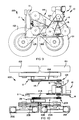
- a low power low speed motorized vehicle in accordance with the invention is generally indicated by reference numeral 100.
- the vehicle 100 has fixed axles mounting, respectively, left fore and rear wheels 101 and 102 and right fore and rear wheels 201 and 202. It is powered by means of the motor/transmission unit 10 as described above and comprising the internal combustion engine 12 and the transmission device generally indicated by reference numeral 14.
- the unit 10 is similar to the unit described with reference to Figures 1 to 7 and the same reference numerals denote the same components.
- the transmission device 14 is adapted to transmit power in the same direction but respectively in low and high ratio in the respective drive modes. It is also capable of interrupting transmission of power in its neutral mode.
- the unit 10 has a common output shaft 16. At one end of the output shaft, as indicated by reference numeral 103, it has two pulleys which are drivingly connected by means of endless flexible drive members 104 to a transmission device in accordance with the invention and generally indicated by reference numeral 111.
- the transmission device 111 is arranged to drive the left fore and rear wheels 101 and 102 in accordance with the invention.
- the output shaft 16 has a pair of pulleys 203 which are drivingly connected by means of flexible drive elements 204 to a further transmission device in accordance with the invention generally indicated by reference numeral 211.
- the device 211 is arranged to drive the right fore and rear wheels 201 and 202.
- the transmission device 214 is arranged in upright orientation (as can best be perceived for the transmission device 114 shown in Figure 9).
- the transmission device 214 is adapted to transmit drive, at the same speed, but respectively in forward and reverse, in its two drive modes. It is also capable of an intermediate neutral mode in which drive is not transmitted.
- Control means generally indicated by reference numeral 11 is provided to control operation of the transmission device 14. Similarly, separate control means 111 and 211 are provided to control respectively the control device 114 and the control device 214.
- rotary power from the internal combustion engine 12 can be transmitted to the respective transmission devices 114 and 214 in a selected one direction either at a high speed ratio or a low speed ratio. It is also capable of being in neutral mode in which drive is not transmitted and the internal combustion engine 12 is allowed merely to idle. It is to be appreciated, as explained above, that a separate friction clutch is not provided.
- Each of the transmission devices 114 and 214 can, selectively, transmit drive to the wheels either in forward or reverse direction. If desired, both the transmission devices can independently be adjusted into neutral mode in which power is not transmitted.
- an operator can propel the vehicle 100 at high speed, at low speed, or can select idling mode. Furthermore, by means of the transmission devices 114 and 214, the operator can propel the vehicle 100 forward or rearward. In addition, because the transmission devices 114 and 214 can be controlled independently, one side of the vehicle can be propelled forward while the other side is propelled rearward or is held stationary in idle mode and by utilizing brakes if desired. In that fashion, pivot steering can be achieved.
- transmission devices in accordance with the invention can be used to transmit drive to a vehicle in a manner in which the vehicle is controllable in a number of ways. It is important to appreciate that the transmission devices are provided relatively inexpensively, and that no separate friction clutch is required.
Landscapes
- Engineering & Computer Science (AREA)
- General Engineering & Computer Science (AREA)
- Mechanical Engineering (AREA)
- Transmission Devices (AREA)
- Arrangement And Driving Of Transmission Devices (AREA)
- Transmissions By Endless Flexible Members (AREA)
- Arrangement Of Transmissions (AREA)
Claims (23)
- Procédé de transmission d'énergie rotative d'une source d'énergie rotative (12) à une charge rotative (16), de manière sélective, dans au moins un premier et un second modes d'entraînement correspondant à une première et une seconde positions fonctionnelles, le procédé comprenant les étapes suivantes :- prévoir un dispositif de transmission (14) qui comporte :. un boîtier (30),. un premier et un second pignons intermédiaires (44 et 54), qui sont montés rotatifs de manière indépendante sur des axes de rotation correspondants (46 et 56),. des moyens de liaison de source (20, 22, 50, 60) fonctionnellement adaptés pour relier respectivement les premier et second pignons intermédiaires à la source d'énergie rotative,. des moyens de liaison de charge (48, 58, 51, 42 ; 148, 158, 151, 142 ; 248, 252, 258, 251, 242 ; 348, 358, 342 ; 448, 452, 458, 442) fonctionnellement aptes à relier la charge rotative respectivement au premier et au second pignons intermédiaires ;- monter le dispositif de transmission par rapport à la source d'énergie rotative et à la charge rotative pour qu'il puisse être déplacé sélectivement entre ladite première position et ladite seconde position fonctionnelles ;- relier la source d'énergie rotative (12) à la charge rotative (16) grâce au moyen de liaison de source et au moyen de liaison de charge, de manière quela liaison d'entraînement dans ledit premier mode d'entraînement soit effective entre la source d'énergie rotative par l'intermédiaire du premier pignon intermédiaire (44) et la charge rotative, et que l'entraînement entre la source d'énergie rotative et la charge rotative par le second pignon intermédiaire (54) soit interrompue, quela liaison d'entraînement dans ledit second mode d'entraînement est effective de la source d'énergie rotative au moyen du second pignon intermédiaire (54) à la charge rotative, et que l'entraînement entre la source d'énergie rotative et la charge rotative par le premier pignon intermédiaire (44) est interrompue, de sorte que le premier mode d'entraînement et le second mode d'entraînement diffèrent l'un de l'autre au moins par le sens de rotation et par le rapport de vitesses ; et- déplacer de manière appropriée le dispositif de transmission pour l'amener dans une position choisie parmi les première et seconde positions fonctionnelles correspondant auxdits premier et second modes d'entraînement,caractérisé en ce qu'il consiste :- à monter lesdits axes de rotation (46 et 56) desdits premier et second pignons intermédiaires (44 et 54) en relation fixe par rapport audit boîtier (30) ; et- à déplacer l'ensemble dudit boîtier (30) par rapport à la source d'énergie rotative pour l'amener dans un état choisi parmi lesdits états fonctionnels afin d'établir ledit premier ou second mode d'entraînement.
- Procédé selon la revendication 1, dans lequel l'ensemble du boîtier (30) est amené à l'état neutre du dispositif de transmission correspondant à un mode neutre pour interrompre la transmission d'énergie entre la source d'énergie rotative et la charge rotative.
- Procédé selon la revendication 2, dans lequel ledit boîtier (30) est monté pivotant, dans lequel les premier et second états fonctionnels correspondent à différentes orientations angulaires dudit boîtier, et dans lequel ledit boîtier est déplacé en pivotement.
- Procédé selon la revendication 3, dans lequel ledit état neutre est intermédiaire entre lesdites première et seconde positions fonctionnelles.
- Procédé selon l'une quelconque des revendications précédentes, dans lequel la charge rotative est reliée en permanence audit premier et second pignons intermédiaires (44 et 54) par ledit moyen de liaison de charge, et dans lequel la source d'énergie rotative est reliée à l'un desdits premier et second pignons intermédiaires (44 et 54), et déconnectée de l'autre par ledit moyen de liaison de source en réponse au mouvement de l'ensemble dudit boîtier.
- Procédé selon la revendication 5, dans lequel l'énergie rotative est transmise par friction auxdits pignons intermédiaires (44, 54), au moyen d'éléments d'entraînement flexibles sans fin (50, 60).
- Procédé selon l'une des revendications 5 ou 6, dans lequel l'énergie rotative des pignons intermédiaires respectifs (44, 54) est transmise à un pignon de sortie (42 ; 142 ; 242 ; 343 ; 442) qui est rigidement relié à la charge rotative (16) par l'intermédiaire des premiers et seconds pignons intermédiaires auxiliaires (48, 58 ; 148, 158 ; 248, 258 ; 348, 358 ; 448, 452, 458) reliés en entraînement aux premier et second pignons intermédiaires respectifs, de sorte que ledit pignon de sortie est relié auxdits premier et second pignons intermédiaires auxiliaires par un moyen de liaison de sortie (51 ; 151 ; 251).
- Dispositif de transmission d'énergie rotative (14) apte à transmettre de l'énergie rotative d'une source d'énergie rotative (12) à une charge rotative (16), de manière sélective selon au moins deux modes d'entraînement, comprenant :- un boîtier (30),- un premier et un second pignons intermédiaires (44 et 54) qui sont montés rotatifs de manière indépendante sur des axes de rotation respectifs (46 et 56),- des moyens de liaison de source (20, 22, 50, 60) fonctionnellement adaptés pour relier respectivement les premier et second pignons intermédiaires à la source d'énergie rotative,- des moyens de liaison de charge (48, 58, 51, 42 ; 148, 158, 151, 142 ; 248, 252, 258, 251, 242 ; 348, 358, 342 ; 448, 452, 458, 442) fonctionnellement aptes à relier la charge rotative respectivement au premier et au second pignons intermédiaires ;- un moyen pour monter le dispositif de transmission par rapport à la source d'énergie rotative et à la charge rotative et pour déplacer sélectivement le dispositif de transmission de manière appropriée entre une première et une seconde positions fonctionnelles correspondant à un premier et à un second mode d'entraînement, dans lequel le dispositif de transmission est apte à relier la source d'énergie rotative (12) à la charge rotative (16) grâce audit moyen de liaison de source et audit moyen de liaison de charge, de manièrequ'une liaison d'entraînement dans ledit premier mode d'entraînement soit effective au moyen du premier pignon intermédiaire (44) entre la source d'énergie rotative et la charge rotative, et que l'entraînement entre la source d'énergie rotative et la charge rotative par le second pignon intermédiaire (54) soit interrompu, etqu'une liaison d'entraînement dans ledit second mode d'entraînement soit effective au moyen du second pignon intermédiaire entre la source d'énergie rotative (54) et la charge rotative, et que l'entraînement entre la source d'énergie rotative et la charge rotative par le premier pignon intermédiaire (44) soit interrompu, de sorte que le premier mode d'entraînement et le second mode d'entraînement diffèrent l'un de l'autre au moins par le sens de rotation et par le rapport de vitesses ;caractérisé en ce que :- les axes de rotation (46 et 56) desdits premier et second pignons intermédiaires (44 et 54) sont en relation fixe par rapport audit boîtier (30) ; et- lesdits moyens de montage et de déplacement sont aptes à déplacer l'ensemble dudit boîtier (30) par rapport à la source d'énergie rotative pour l'amener dans une position choisie parmi lesdites positions fonctionnelles afin d'établir ledit premier ou second mode d'entraînement.
- Dispositif selon la revendication 8, dans lequel lesdits moyens de montage et de déplacement sont aptes à permettre un mouvement de l'ensemble du boîtier jusqu'à une position neutre correspondant à un mode neutre dans lequel la transmission d'énergie est interrompue.
- Dispositif selon la revendication 9, dans lequel ladite position neutre est intermédiaire entre lesdites première et seconde positions fonctionnelles.
- Dispositif selon l'une quelconque des revendications 8 à 10, dans lequel ledit moyen de montage est un moyen de montage pivotant (16, 32) tel que l'ensemble du boîtier (30) soit pivotant entre sa première et sa seconde positions fonctionnelles.
- Dispositif selon l'une quelconque des revendications précédentes 8 à 10, dans lequel la charge rotative est reliée en permanence auxdits premier et second pignons intermédiaires (44 et 54) par ledit moyen de liaison de charge, et dans lequel la source d'énergie rotative est reliée à l'un desdits premier et second pignons intermédiaires (44 et 54), et est déconnecté de l'autre par ledit moyen de liaison de source en réponse au mouvement de l'ensemble dudit boîtier.
- Dispositif selon la revendication 12, comprenant un élément pivotant (38) au moyen duquel le boîtier (30) peut pivoter à la manière d'un pendule autour des axes de la charge de sortie (16).
- Dispositif selon l'une des revendications 12 ou 13, dans lequel le premier et le second pignons intermédiaires ont la forme de poulies (44, 54), et dans lequel la liaison d'entraînement entre la source d'énergie rotative et les pignons intermédiaires respectifs se fait par friction au moyen de courroies (50, 60).
- Dispositif selon l'une quelconque des revendications 12 à 14, dans lequel le moyen de liaison de charge comprend :- un premier pignon intermédiaire auxiliaire (48) et un second pignon intermédiaire auxiliaire (58) qui sont respectivement reliés en entraînement aux premier et second pignons intermédiaires (44 et 54),- un pignon de sortie (42) relié à ladite charge rotative, et- un moyen de liaison de sortie (51 ; 151) reliant en entraînement le pignon de sortie aux premier et second pignons intermédiaires auxiliaires.
- Dispositif selon la revendication 15, dans lequel le premier pignon intermédiaire et le premier pignon intermédiaire auxiliaire sont reliés rigidement en entraînement autour d'un axe commun (46), et dans lequel le second pignon intermédiaire et le second pignon intermédiaire auxiliaire sont reliés rigidement en entraînement autour d'un axe commun (56).
- Dispositif selon l'une des revendications 15 ou 16, dans lequel les pignons intermédiaires auxiliaires (48, 58) et le pignon de sortie (42) ont la forme de poulies, et dans lequel le moyen de liaison de sortie a la forme d'une courroie trapézoïdale complémentaire (51).
- Dispositif selon l'une des revendications 15 ou 16, dans lequel les pignons intermédiaires auxiliaires (148, 158) et le pignon de sortie (142) ont la forme de pignons de chaîne, et dans lequel le moyen de liaison de sortie a la forme d'une chaîne complémentaire (151).
- Dispositif selon l'une des revendications 15 ou 16, dans lequel les pignons intermédiaires auxiliaires (348, 448 ; 358, 458) et le pignon de sortie (342, 442) ont la forme de pignons d'engrenage, et dans lequel le moyen de liaison de sortie est formé par un agencement (452) sollicitant les pignons d'engrenage à s'engrener.
- Dispositif selon la revendication 14, dans lequel les pignons intermédiaires ont la forme de poulies ajustables (70) pour permettre d'ajuster les diamètres relatifs des poulies afin d'obtenir un ajustement de vitesse.
- Dispositif selon la revendication 14, dans lequel les pignons intermédiaires ont la forme de poulies multiples pour permettre de choisir différents rapports de vitesses.
- Dispositif d'installation (100) comprenant une source d'énergie rotative (12) et une charge rotative, et comprend un dispositif de transmission selon l'une quelconque des revendications 8 à 21, pour transmettre l'énergie rotative de la source d'énergie rotative à la charge rotative.
- Dispositif d'installation selon la revendication 22 sous la forme d'un véhicule à moteur (100), dans lequel un pignon d'entraînement (101, 102, 201, 202) du véhicule forme la charge rotative.
Applications Claiming Priority (2)
| Application Number | Priority Date | Filing Date | Title |
|---|---|---|---|
| ZA922306 | 1992-03-30 | ||
| ZA922306 | 1992-03-30 |
Publications (2)
| Publication Number | Publication Date |
|---|---|
| EP0564221A1 EP0564221A1 (fr) | 1993-10-06 |
| EP0564221B1 true EP0564221B1 (fr) | 1997-09-10 |
Family
ID=66912157
Family Applications (1)
| Application Number | Title | Priority Date | Filing Date |
|---|---|---|---|
| EP93302452A Expired - Lifetime EP0564221B1 (fr) | 1992-03-30 | 1993-03-30 | Transmission de puissance rotative |
Country Status (10)
| Country | Link |
|---|---|
| US (1) | US5393270A (fr) |
| EP (1) | EP0564221B1 (fr) |
| JP (1) | JPH0642599A (fr) |
| KR (1) | KR930020054A (fr) |
| AP (1) | AP394A (fr) |
| AT (1) | ATE158065T1 (fr) |
| AU (1) | AU663835B2 (fr) |
| DE (1) | DE69313698T2 (fr) |
| MY (1) | MY109124A (fr) |
| ZA (1) | ZA932281B (fr) |
Families Citing this family (9)
| Publication number | Priority date | Publication date | Assignee | Title |
|---|---|---|---|---|
| AUPM816594A0 (en) * | 1994-09-15 | 1994-10-13 | Garvin, Robert Arnold | Glass shaping machine |
| KR0129767Y1 (ko) * | 1996-01-17 | 1998-12-01 | 엄성섭 | 로더의 차륜 구동장치 |
| US7252027B2 (en) * | 2001-02-08 | 2007-08-07 | Black & Decker Inc. | Miter saw |
| JP2003165254A (ja) * | 2001-11-30 | 2003-06-10 | Fuji Xerox Co Ltd | 画像記録装置 |
| JP4356898B2 (ja) * | 2006-11-27 | 2009-11-04 | 本田技研工業株式会社 | 回転方向切換装置 |
| JP5033709B2 (ja) * | 2008-05-21 | 2012-09-26 | 本田技研工業株式会社 | 動力伝達装置 |
| US8182380B2 (en) * | 2008-05-21 | 2012-05-22 | Honda Motor Co., Ltd. | Power transmission device |
| WO2016201263A1 (fr) * | 2015-06-12 | 2016-12-15 | Mtd Products Inc | Souffleuse à neige ayant une roue à aubes à vitesses multiples |
| IT202200025833A1 (it) | 2022-12-16 | 2024-06-16 | Ital Res & Innovation Srl | Macchina combinata ad azionamento selettivo |
Family Cites Families (18)
| Publication number | Priority date | Publication date | Assignee | Title |
|---|---|---|---|---|
| GB575022A (en) * | 1944-06-05 | 1946-01-30 | Bomford & Evershed Ltd | Improvements relating to variable speed driving and reversing gear or mechanism for motor vehicles |
| FR1020039A (fr) * | 1950-06-12 | 1953-01-30 | Bichier & Cie | Dispositif de commande à changement de vitesse |
| US3721132A (en) * | 1971-04-28 | 1973-03-20 | Johnson Farm Machinery Co Inc | Intermittent drive for conveyors and the like |
| US3722277A (en) * | 1971-05-11 | 1973-03-27 | Hesston Corp | Transmission having direction control |
| US3728905A (en) * | 1972-01-07 | 1973-04-24 | Hesston Corp | Belt transmission having mechanism for reverse grinding |
| US3731557A (en) * | 1972-03-29 | 1973-05-08 | Simplicity Mfg Co Inc | Planetary transmission |
| US3938400A (en) * | 1974-10-02 | 1976-02-17 | Allis-Chalmers Corporation | Single lever forward-reverse control |
| US4132121A (en) * | 1977-04-27 | 1979-01-02 | Clarke George C | Variable speed drive |
| US4237983A (en) * | 1978-12-07 | 1980-12-09 | Allen Douglas E | Combination tiller and cultivator and reversible drive assembly therefor |
| JPS5631887A (en) * | 1979-08-21 | 1981-03-31 | Honda Motor Co Ltd | Transmitting case device for autobicycle |
| US4340377A (en) * | 1980-06-23 | 1982-07-20 | Hamilton Bros. Mfg. Co. | Speed change device |
| DE3133922C2 (de) * | 1981-08-27 | 1987-01-08 | Johann 5451 Datzeroth Kleber | Schubkarren |
| US4471856A (en) * | 1982-08-13 | 1984-09-18 | Magee John E | Elevator door interlock |
| US4771856A (en) * | 1986-10-27 | 1988-09-20 | Deere & Company | Single lever control for vehicle belt drive |
| US4696661A (en) * | 1986-12-22 | 1987-09-29 | Weber Rehlander | Forward-reverse belt transmission |
| US4768997A (en) * | 1987-03-10 | 1988-09-06 | Tecumseh Products Company | Belt drive system for dual input transmissions/transaxles |
| DE3922317A1 (de) * | 1989-07-07 | 1991-01-17 | Wegmann & Co | Geschosstransporter, insbesondere fuer ein kampffahrzeug |
| FR2667123A1 (fr) * | 1990-09-21 | 1992-03-27 | Staub Tracteurs Motocult | Transmission a courroies debrayable, a traitement dans les deux sens de rotation. |
-
1993
- 1993-03-29 US US08/038,004 patent/US5393270A/en not_active Expired - Fee Related
- 1993-03-29 AP APAP/P/1993/000503A patent/AP394A/en active
- 1993-03-29 AU AU35542/93A patent/AU663835B2/en not_active Ceased
- 1993-03-29 MY MYPI93000545A patent/MY109124A/en unknown
- 1993-03-29 KR KR1019930004993A patent/KR930020054A/ko not_active Ceased
- 1993-03-30 DE DE69313698T patent/DE69313698T2/de not_active Expired - Fee Related
- 1993-03-30 ZA ZA932281A patent/ZA932281B/xx unknown
- 1993-03-30 EP EP93302452A patent/EP0564221B1/fr not_active Expired - Lifetime
- 1993-03-30 AT AT93302452T patent/ATE158065T1/de not_active IP Right Cessation
- 1993-03-30 JP JP5072239A patent/JPH0642599A/ja not_active Withdrawn
Also Published As
| Publication number | Publication date |
|---|---|
| JPH0642599A (ja) | 1994-02-15 |
| MY109124A (en) | 1996-12-31 |
| ZA932281B (en) | 1993-10-18 |
| AU3554293A (en) | 1993-10-07 |
| KR930020054A (ko) | 1993-10-19 |
| ATE158065T1 (de) | 1997-09-15 |
| DE69313698T2 (de) | 1998-01-08 |
| US5393270A (en) | 1995-02-28 |
| AP9300503A0 (en) | 1993-04-30 |
| EP0564221A1 (fr) | 1993-10-06 |
| AP394A (en) | 1995-08-07 |
| AU663835B2 (en) | 1995-10-19 |
| DE69313698D1 (de) | 1997-10-16 |
Similar Documents
| Publication | Publication Date | Title |
|---|---|---|
| KR100200470B1 (ko) | 무단변속 구동차량의 조타제어장치 | |
| EP0564221B1 (fr) | Transmission de puissance rotative | |
| CA1096200A (fr) | Traduction non-disponible | |
| CA1077400A (fr) | Element moteur combine a courroie et commande hydrostatique pour vehicule | |
| EP1745972B1 (fr) | Tracteur | |
| US6293888B1 (en) | Wide ratio coverage continuously variable transmission | |
| KR20100057673A (ko) | 차량용 연속 가변 변속 장치 | |
| US5194049A (en) | Combined directional and infinitely variable-speed transmission | |
| KR100519855B1 (ko) | 차량용변속조작장치 | |
| EP0757190A1 (fr) | Tendeur de chaîne élastique bidirectionnel | |
| JPH0661180B2 (ja) | 作業車輌における動力伝達装置 | |
| US20220221036A1 (en) | Multiple-Purpose Vehicle | |
| JPH04224353A (ja) | 車両用の駆動ユニット | |
| US6951523B1 (en) | Mechanical variable reversible transmission | |
| JP4508337B2 (ja) | 走行装置 | |
| JP3098154B2 (ja) | 乗用移動農機におけるミッションケース | |
| JP3552256B2 (ja) | コンバインの刈取伝動装置 | |
| JP3032479B2 (ja) | 作業車の伝動構造 | |
| JP3116036B2 (ja) | 田植機における無段変速装置 | |
| JP2906242B2 (ja) | 車両用無段自動変速機 | |
| JPH06166334A (ja) | ハンドトラクタ−における伝動装置 | |
| JP3032480B2 (ja) | 作業車の伝動構造 | |
| KR100231241B1 (ko) | 엔진동력전달용 벨트전동장치 | |
| JP4036573B2 (ja) | 乗用作業車 | |
| JP3729300B2 (ja) | 無段変速機付き歩行型車両の変速操作装置 |
Legal Events
| Date | Code | Title | Description |
|---|---|---|---|
| PUAI | Public reference made under article 153(3) epc to a published international application that has entered the european phase |
Free format text: ORIGINAL CODE: 0009012 |
|
| AK | Designated contracting states |
Kind code of ref document: A1 Designated state(s): AT BE CH DE DK ES FR GB GR IE IT LI LU MC NL PT SE |
|
| 17P | Request for examination filed |
Effective date: 19940202 |
|
| 17Q | First examination report despatched |
Effective date: 19950510 |
|
| GRAG | Despatch of communication of intention to grant |
Free format text: ORIGINAL CODE: EPIDOS AGRA |
|
| GRAH | Despatch of communication of intention to grant a patent |
Free format text: ORIGINAL CODE: EPIDOS IGRA |
|
| GRAH | Despatch of communication of intention to grant a patent |
Free format text: ORIGINAL CODE: EPIDOS IGRA |
|
| GRAA | (expected) grant |
Free format text: ORIGINAL CODE: 0009210 |
|
| AK | Designated contracting states |
Kind code of ref document: B1 Designated state(s): AT BE CH DE DK ES FR GB GR IE IT LI LU MC NL PT SE |
|
| PG25 | Lapsed in a contracting state [announced via postgrant information from national office to epo] |
Ref country code: NL Free format text: LAPSE BECAUSE OF FAILURE TO SUBMIT A TRANSLATION OF THE DESCRIPTION OR TO PAY THE FEE WITHIN THE PRESCRIBED TIME-LIMIT Effective date: 19970910 Ref country code: LI Effective date: 19970910 Ref country code: GR Free format text: LAPSE BECAUSE OF FAILURE TO SUBMIT A TRANSLATION OF THE DESCRIPTION OR TO PAY THE FEE WITHIN THE PRESCRIBED TIME-LIMIT Effective date: 19970910 Ref country code: ES Free format text: THE PATENT HAS BEEN ANNULLED BY A DECISION OF A NATIONAL AUTHORITY Effective date: 19970910 Ref country code: DK Free format text: LAPSE BECAUSE OF NON-PAYMENT OF DUE FEES Effective date: 19970910 Ref country code: CH Effective date: 19970910 Ref country code: BE Effective date: 19970910 Ref country code: AT Effective date: 19970910 |
|
| REF | Corresponds to: |
Ref document number: 158065 Country of ref document: AT Date of ref document: 19970915 Kind code of ref document: T |
|
| REG | Reference to a national code |
Ref country code: CH Ref legal event code: EP |
|
| REF | Corresponds to: |
Ref document number: 69313698 Country of ref document: DE Date of ref document: 19971016 |
|
| ITF | It: translation for a ep patent filed | ||
| PG25 | Lapsed in a contracting state [announced via postgrant information from national office to epo] |
Ref country code: SE Effective date: 19971210 Ref country code: PT Effective date: 19971210 |
|
| ET | Fr: translation filed | ||
| REG | Reference to a national code |
Ref country code: IE Ref legal event code: FG4D Free format text: 76340 |
|
| NLV1 | Nl: lapsed or annulled due to failure to fulfill the requirements of art. 29p and 29m of the patents act | ||
| REG | Reference to a national code |
Ref country code: CH Ref legal event code: PL |
|
| PG25 | Lapsed in a contracting state [announced via postgrant information from national office to epo] |
Ref country code: LU Free format text: LAPSE BECAUSE OF NON-PAYMENT OF DUE FEES Effective date: 19980330 Ref country code: IE Free format text: LAPSE BECAUSE OF NON-PAYMENT OF DUE FEES Effective date: 19980330 |
|
| PLBE | No opposition filed within time limit |
Free format text: ORIGINAL CODE: 0009261 |
|
| STAA | Information on the status of an ep patent application or granted ep patent |
Free format text: STATUS: NO OPPOSITION FILED WITHIN TIME LIMIT |
|
| 26N | No opposition filed | ||
| PG25 | Lapsed in a contracting state [announced via postgrant information from national office to epo] |
Ref country code: MC Free format text: LAPSE BECAUSE OF NON-PAYMENT OF DUE FEES Effective date: 19980930 |
|
| PGFP | Annual fee paid to national office [announced via postgrant information from national office to epo] |
Ref country code: GB Payment date: 19990216 Year of fee payment: 7 |
|
| PGFP | Annual fee paid to national office [announced via postgrant information from national office to epo] |
Ref country code: FR Payment date: 19990226 Year of fee payment: 7 |
|
| PGFP | Annual fee paid to national office [announced via postgrant information from national office to epo] |
Ref country code: DE Payment date: 19990505 Year of fee payment: 7 |
|
| PG25 | Lapsed in a contracting state [announced via postgrant information from national office to epo] |
Ref country code: GB Free format text: LAPSE BECAUSE OF NON-PAYMENT OF DUE FEES Effective date: 20000330 |
|
| GBPC | Gb: european patent ceased through non-payment of renewal fee |
Effective date: 20000330 |
|
| PG25 | Lapsed in a contracting state [announced via postgrant information from national office to epo] |
Ref country code: FR Free format text: LAPSE BECAUSE OF NON-PAYMENT OF DUE FEES Effective date: 20001130 |
|
| REG | Reference to a national code |
Ref country code: FR Ref legal event code: ST |
|
| PG25 | Lapsed in a contracting state [announced via postgrant information from national office to epo] |
Ref country code: DE Free format text: LAPSE BECAUSE OF NON-PAYMENT OF DUE FEES Effective date: 20010103 |
|
| REG | Reference to a national code |
Ref country code: IE Ref legal event code: MM4A |
|
| PG25 | Lapsed in a contracting state [announced via postgrant information from national office to epo] |
Ref country code: IT Free format text: LAPSE BECAUSE OF NON-PAYMENT OF DUE FEES Effective date: 20050330 |