EP0564324A1 - Dämpfer-Antriebszylinder für das Fahrwerk eines Flugzeuges, insbesondere für Hubschrauber - Google Patents
Dämpfer-Antriebszylinder für das Fahrwerk eines Flugzeuges, insbesondere für Hubschrauber Download PDFInfo
- Publication number
- EP0564324A1 EP0564324A1 EP93400751A EP93400751A EP0564324A1 EP 0564324 A1 EP0564324 A1 EP 0564324A1 EP 93400751 A EP93400751 A EP 93400751A EP 93400751 A EP93400751 A EP 93400751A EP 0564324 A1 EP0564324 A1 EP 0564324A1
- Authority
- EP
- European Patent Office
- Prior art keywords
- rod
- cylindrical body
- shock absorber
- piston
- stop
- Prior art date
- Legal status (The legal status is an assumption and is not a legal conclusion. Google has not performed a legal analysis and makes no representation as to the accuracy of the status listed.)
- Withdrawn
Links
- 239000012530 fluid Substances 0.000 claims abstract description 47
- 230000035939 shock Effects 0.000 claims description 27
- 238000007667 floating Methods 0.000 claims description 8
- 238000013016 damping Methods 0.000 claims description 7
- 238000010521 absorption reaction Methods 0.000 claims description 6
- 238000007789 sealing Methods 0.000 claims description 6
- 238000004891 communication Methods 0.000 claims description 5
- 238000010008 shearing Methods 0.000 claims description 3
- 239000006096 absorbing agent Substances 0.000 description 10
- 239000007789 gas Substances 0.000 description 7
- 238000005096 rolling process Methods 0.000 description 7
- 239000002131 composite material Substances 0.000 description 6
- 238000005192 partition Methods 0.000 description 4
- IJGRMHOSHXDMSA-UHFFFAOYSA-N Atomic nitrogen Chemical compound N#N IJGRMHOSHXDMSA-UHFFFAOYSA-N 0.000 description 2
- 238000006243 chemical reaction Methods 0.000 description 2
- 230000006835 compression Effects 0.000 description 2
- 238000007906 compression Methods 0.000 description 2
- 230000003068 static effect Effects 0.000 description 2
- 229910000497 Amalgam Inorganic materials 0.000 description 1
- 229920000049 Carbon (fiber) Polymers 0.000 description 1
- 239000004917 carbon fiber Substances 0.000 description 1
- 210000004027 cell Anatomy 0.000 description 1
- 239000000470 constituent Substances 0.000 description 1
- 238000005553 drilling Methods 0.000 description 1
- 239000012528 membrane Substances 0.000 description 1
- 238000000034 method Methods 0.000 description 1
- 229910052757 nitrogen Inorganic materials 0.000 description 1
- 239000000843 powder Substances 0.000 description 1
- 230000001739 rebound effect Effects 0.000 description 1
- 229920005989 resin Polymers 0.000 description 1
- 239000011347 resin Substances 0.000 description 1
- 238000000926 separation method Methods 0.000 description 1
- 239000002689 soil Substances 0.000 description 1
- 239000007787 solid Substances 0.000 description 1
- 230000001960 triggered effect Effects 0.000 description 1
Images

Classifications
-
- F—MECHANICAL ENGINEERING; LIGHTING; HEATING; WEAPONS; BLASTING
- F16—ENGINEERING ELEMENTS AND UNITS; GENERAL MEASURES FOR PRODUCING AND MAINTAINING EFFECTIVE FUNCTIONING OF MACHINES OR INSTALLATIONS; THERMAL INSULATION IN GENERAL
- F16F—SPRINGS; SHOCK-ABSORBERS; MEANS FOR DAMPING VIBRATION
- F16F9/00—Springs, vibration-dampers, shock-absorbers, or similarly-constructed movement-dampers using a fluid or the equivalent as damping medium
- F16F9/06—Springs, vibration-dampers, shock-absorbers, or similarly-constructed movement-dampers using a fluid or the equivalent as damping medium using both gas and liquid
-
- B—PERFORMING OPERATIONS; TRANSPORTING
- B64—AIRCRAFT; AVIATION; COSMONAUTICS
- B64C—AEROPLANES; HELICOPTERS
- B64C25/00—Alighting gear
- B64C25/32—Alighting gear characterised by elements which contact the ground or similar surface
- B64C25/58—Arrangements or adaptations of shock-absorbers or springs
- B64C25/60—Oleo legs
-
- B—PERFORMING OPERATIONS; TRANSPORTING
- B64—AIRCRAFT; AVIATION; COSMONAUTICS
- B64C—AEROPLANES; HELICOPTERS
- B64C25/00—Alighting gear
- B64C25/001—Devices not provided for in the groups B64C25/02 - B64C25/68
- B64C2025/008—Comprising means for modifying their length, e.g. for kneeling, for jumping, or for leveling the aircraft
Definitions
- the present invention relates to a damper-jack intended for the equipment of landing gear of aerodynes, in particular of helicopters, being designed to be able to face a situation of landing in catastrophe (situation commonly called "crash") .
- Low pressure chamber dampers are thus known which are equipped with force clipping means in the form of a separating piston delimiting a chamber of gaseous fluid at high pressure.
- force clipping means in the form of a separating piston delimiting a chamber of gaseous fluid at high pressure.
- the vertical reaction of the soil causes the rod to re-enter the main body, which is accompanied by compression of the gas volume contained in the low pressure chamber, this movement of reentry being braked by a rolling device.
- the pressure induced by the rolling device is communicated by the oil from the cylinder to the piston. separator, and, as the pressure then applied to the separator piston exceeds the inflation pressure of the high pressure chamber, said piston descends by compressing said chamber.
- shock absorbers are currently used to equip landing gear for planes or helicopters, but they are not designed to additionally provide a jack function for lowering and lifting operations, so that this function is ensured by a separate actuator.
- damper-cylinder a damper which is also capable of ensuring a cylinder function
- a damper-jack comprising a cylindrical body, and a hollow rod with open end forming an annular piston sliding with sealing in this cylindrical body, as well as a hydraulic damping means with diaphragm surmounted by a volume of hydraulic fluid delimiting a gaseous fluid chamber (for example nitrogen) at low pressure, and a force clipping means intervening in the event of a crash landing.
- a gaseous fluid chamber for example nitrogen
- Document FR-A-2 608 242 describes a damper-jack of this type, more precisely comprising a main body arranged at the bottom and a piston rod arranged at the top, the main body comprising at the lower end a high pressure chamber which is adjacent , by a flexible separation membrane which can be supported on a rigid perforated support integral with said body, with a low pressure chamber, as well as a rolling device braking the movements of the rod in the main body by rolling the fluid contained in said body and adjacent to the low pressure chamber.
- the piston rod is hollow, and receives a separating piston delimiting two hydraulic chambers.
- the rolling device includes a central pressure relief valve intervening in the event of a sudden depression of the rod, and this device is also associated with a cylindrical-conical tube forming an energy absorber by plastic deformation.
- the jack function is ensured by providing for the connection of two hydraulic chambers (a retraction or raising chamber of the undercarriage controlling the re-entry of the rod into the body, and a chamber lowering or lowering of the undercarriage controlling the exit of the rod from the body) to a hydraulic distributor block which can thus supply the chambers with pressurized hydraulic fluid or authorize their emptying towards a tank in the hydraulic circuit of the 'aerodyne.
- Such a damper-cylinder remains relatively complex, however, and requires in particular a speed-controlled rolling device which must be adjusted with precision.
- the object of the invention is to design a damper-jack which is both efficient in a crash landing situation, and comprises a minimum number of components.
- the object of the invention is also to produce a damper-jack whose force clipping means intervenes automatically in the event of a crash landing, without having to provide a special valve controlled by speed, and whose structure allows, for the cylinder function, to use only a relatively small volume of hydraulic fluid.
- a damper-jack intended for the equipment of landing gear of aerodynes, in particular of helicopters, comprising a cylindrical body, and a hollow rod with open end forming an annular piston sliding with sealing in this body cylindrical, as well as a hydraulic damping means with diaphragm surmounted by a volume of hydraulic fluid delimiting a gaseous fluid chamber at low pressure, and a means for clipping forces intervening in the event of a crash landing, characterized in that the cylindrical body comprises a separating piston movable between two associated stops and delimiting two fluid chambers hydraulic, one of which communicates directly with the interior of the hollow rod in which the hydraulic damping means with diaphragm is disposed, and the other communicates, via a first distributor, with the hydraulic circuit of the aerodyne, this first distributor being automatically closed at the end of the descent of the undercarriage, said cylindrical body and said hollow rod further delimiting an annular chamber which also communicates, via a second distributor, with said hydraulic circuit , said first and second said distributor
- the force clipping means comprises a high-pressure gaseous fluid chamber arranged in an extension of the cylindrical body.
- the piston rod is associated with the high pressure chamber, with a piston sliding in said chamber and a rod which passes through an intermediate bottom of the cylindrical body, said intermediate bottom forming a stop for the separating piston and having means of communication. direct floating valve.
- the hydraulic fluid chamber delimited by the intermediate bottom of the cylindrical body and by the separating piston communicates with the hydraulic circuit of the aerodyne by a first orifice of said body arranged in the vicinity said intermediate bottom.
- the separating piston slides on the rod of the movable piston rod, and the other stop of said separating piston is carried by said rod; in addition, the rod of the movable piston rod can end in a widening which constitutes both the other stop of the separating piston, and a stop for the hollow rod in the normal retraction position. It is also interesting that the hollow rod externally has an end of travel stop cooperating with the free edge of the cylindrical body to limit the retraction stroke in the event of a crash landing.
- the force clipping means comprises a tube whose crushing provides the desired energy absorption, this tube being housed in an extension body which telescopically receives the cylindrical body.
- the cylindrical body and the extension body are linked together by at least one pin which is designed to break by shearing under a predetermined force.
- extension body carries a hollow central rod which passes through the bottom of the cylindrical body forming a stop for the separating piston, said hollow rod having a lateral orifice through which the hydraulic fluid chamber delimited by said bottom and said separating piston communicates with the hydraulic circuit of the aerodyne, via an associated orifice of said extension body.
- the separating piston slides on the hollow central rod of the extension body, and the other stop of said separating piston is carried by said hollow central rod.
- the hollow central rod ends in an enlargement which constitutes both the other stop of the piston separator, and a stop for the hollow rod limiting the retraction stroke in the event of a crash landing.
- the hollow rod it is also advantageous for the hollow rod to present externally an end-of-travel stop cooperating with the free edge of the cylindrical body at the end of normal retraction.
- a deformable anti-rotation means for example an elastic blade, is provided between the cylindrical body and the extension body.
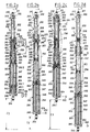
- FIGS. 1a to 1d illustrate a damper-jack 100 according to the invention, intended for the equipment of an aerodyne undercarriage, for example of a helicopter undercarriage.
- the damper-jack 100 has a cylindrical body 101 and a hollow rod 102 sliding with sealing in this cylindrical body, along the axis X thereof.
- the damper-jack 100 can be articulated by its rod on the structure of the aerodyne, and by its body on the lifting undercarriage of this aerodyne.
- the upper end 110 of the hollow rod 102 will then be articulated by means of a ball joint 111 on the structure of the helicopter, while the cylindrical body 101 will be articulated by means of a swivel end piece 114 on the undercarriage rocker, which is itself articulated on the structure of the helicopter, so that the fully extended position illustrated in FIG. 1d corresponds to the lander lowered, while the retracted position of Figure 1c corresponds to the lander raised.
- the hollow rod 102 has an open end on the side of the interior of the cylindrical body 101, with a rod portion 106 and a piston portion 108 which slide with sealing, thanks to associated seals 107 and 109, in the cylindrical body 101.
- the hollow rod 102 is further equipped with a diaphragm hydraulic damping means 115, surmounted by a volume of hydraulic fluid 120 which delimits a chamber of gaseous fluid at low pressure 121, the closed end 110 of the hollow rod 102 comprising a filling and inflation valve 122.
- the diaphragm hydraulic damping means may be of conventional type, such as that illustrated here, with an intermediate partition 116 having passage openings 117, and surmounted by a central pin 118 on which slides a floating valve 119 whose stroke is limited by an enlargement of the end of the pin 118.
- the floating valve 119 When the floating valve 119 is detached from the partition 1 16, the hydraulic fluid passes through the orifices 117 in the chamber 120, which corresponds to a phase of compression of the low pressure chamber 121.
- the floating valve 119 is supported on the bottom 116, it controls the rolling by means of holes (not visible here) provided at level of at least some of the passage orifices 117, according to a well known technique.
- the cylindrical body 101 comprises a main portion 103, delimited below by a bottom 104 and above by an enlarged portion 105, which defines, with the piston rod 102, an annular chamber 124.
- the cylindrical body 101 comprises a separating piston 126 delimiting two chambers of hydraulic fluid 127 and 128, one of which (in this case the chamber 127) communicates directly with the interior of the hollow rod 102, and the other (in this case the chamber 128) communicates via a first distributor 130, with the hydraulic circuit of the aerodyne, and the annular chamber 124 also communicates with this hydraulic circuit by through a second distributor 125.
- the main part 103 of the cylindrical body 101 has an end orifice 123 for the connection of the distributor 125, and, near the bottom 104, an orifice 129 for the connection with distributor 130.
- the first distributor 130 and the second distributor 125 make it possible to control the extension or retraction of the damper-jack 100 for the descent or the raising of the undercarriage, and the first distributor 130 is further arranged to be automatically (by example by means of an ad hoc sensor or an adapted time delay) closed at the end of the landing of the lander.
- two distributors 125 and 130 are thus shown with three connection lines denoted X, R and A, respectively associated with the closure, the return to the circuit cover, and the supply of pressurized fluid (for more than clarity, these same distributors have only been shown diagrammatically in FIGS. 1b, 1c and 1d).
- the damper-jack 100 includes a force clipping means which is arranged in an extension 112 extending beyond the aforementioned bottom 104 of the cylindrical body 101, which bottom forms one of the stops of the separating piston 126.
- the extension 112 is nothing other than an extension of the cylindrical body 101, which ends in a bottom 113 on which is arranged the above-mentioned swivel end piece 114 associated with the articulation with the balance of the lander.
- the bottom 104 is in this case an intermediate bottom, so that the bottoms 104 and 113 delimit, internally at the extension 112, a chamber 140 of gaseous fluid at high pressure, the inflation of this chamber being ensured by an associated valve 141 , and a small amount of hydraulic fluid 142 being, as usual, provided on the bottom 113 of this high pressure chamber.
- the force clipping means further comprises a movable piston rod 135 which is associated with the high pressure chamber 140, with a piston 136 sliding with sealing, by an associated seal 138, in the high pressure chamber 140, and a rod 137 which passes through the intermediate bottom 104 of the cylindrical body 101.
- the intermediate bottom 104 comprises communication means 131, with passage orifices 132, and, on the side of the piston 136, a floating valve 133 whose detachment stroke of the orifices mentioned above is limited by an associated stop 134.
- the separating piston 126 slides on the rod 137, said piston having seals (not referenced) to ensure the sliding seal on the rod 137, and against the inner surface of the cylindrical body 103.
- the rod 137 ends in a widening 139 which constitutes the other stop of the separator piston 126, completing the first stop constituted by the intermediate bottom 104.
- the separator piston 126 is thus movable between a low stop position (for example illustrated in FIGS. 1a and 1c), and a position high stop against the widening 139 of the rod 137 (as illustrated in Figures 1b and 1d).
- the enlargement 139 of the rod 137 fulfills an additional function, also constituting a stop for the hollow rod 102 in the normal retraction position.
- the distributor 125 When the landing gear is lowered, the distributor 125 is actuated so as to put the orifice 123 of the annular chamber 124 into communication with the cover of the hydraulic circuit (not shown here) of the aerodyne (by the line R), and the distributor 130 ensures the supply of pressurized fluid through the orifice 129 (via line A).
- the piston separator 126 first rises from the intermediate bottom 104 and pushes the hollow rod 102 out of the cylindrical body 103, until this separating piston comes into high abutment against the widening 139 of the rod 137.
- the extension continues then by a complete exit from the hollow rod 102, a certain volume of fluid from the chamber 120 passing through the chamber 127 under the action of the gas contained in the low pressure chamber 121.
- the final position is then that which is illustrated on the FIG. 1d, and, as soon as this position is reached, the distributor 130 closes automatically (line X).
- the damper-jack 100 then behaves like a conventional shock absorber.
- the hydraulic fluid contained in the chamber 128, and the separating piston 126 which overcomes this volume constitute a rigid monolithic assembly which is perceived for the shock absorber as a bottom.
- the fluid in the chamber 127 passes through the orifices 117 in the hydraulic chamber 120, compressing the gas from the low pressure chamber 121, the floating valve 119 being lifted during this movement of fluid.
- FIG. 1b thus illustrates a position which corresponds to the damper-jack under static or dynamic load, the retraction stroke relative to the fully relaxed position then being denoted C2.
- the entire lower part of the damper-jack behaves like a monolithic inert assembly.
- the force clipping means is automatically triggered, that is to say that a significant part of the hydraulic fluid contained in the hydraulic chamber 128, and which relates to the fluid of the circuit of the aerodyne, passes rapidly into the extension 112 by pushing the piston 136 of the mobile piston rod 135, and by compressing the gas from the high pressure chamber 140. There is also a certain transit of volume of fluid passing through the chamber 120 of the hollow rod 102, by compressing the gas from the low pressure chamber 121.
- the shock absorber-jack 100 is thus able to retract very quickly, absorbing energy, and this up to a stop position which is here given by the contact between the stop 143 of the hollow rod and the upper edge. 144 of the cylindrical body.
- the final position is then that which is illustrated in FIG. 1a, and the retraction stroke relative to the completely relaxed position in FIG. 1d has been denoted C1.
- the floating valve 133 which has uncovered the orifices 132 during the transit of hydraulic fluid to the high pressure chamber 140, returns, once the final position has been reached, against these orifices, and ensures by ad hoc drilling (not visible here) trigger control, which avoids an unfavorable rebound effect.
- the damper-jack 100 After take-off, the damper-jack 100 progressively passes from the position illustrated in FIG. 1b to the completely relaxed position illustrated in FIG. 1d. Then, the distributor 130 is actuated to ensure the emptying of the fluid chamber 128 (by the line R), and the distributor 125 ensures the supply of pressurized fluid through the associated orifice 123 (by the line A). The emptying of the fluid chamber 128 lowers the separator piston 126 until it comes to a stop. low against the intermediate bottom 104. Finally, the fluid passing through the interior of the hollow rod 102 compresses the gas from the low-pressure chamber 121, and the retraction of the hollow rod into the cylindrical body continues until the stop, against the widening 139, of the piston rod then stationary 135. The damper-jack finally arrives at the raised position illustrated in FIG. 1c. Once the lifting is completed, the distributor 125 closes the orifice 123 to ensure the locking of the damper-jack.
- the damper-jack 100 which has just been described has many practical advantages: in addition to the simplicity of its structure, it makes it possible to obtain a clipping of forces effected automatically by the high pressure chamber, so that it becomes unnecessary to provide a special distributor controlled by speed, and moreover the volume of hydraulic fluid associated with the jack function is relatively small.
- FIGS. 2a, 2b, 2c, 2d Another variant of the damper-jack according to the invention has been illustrated in FIGS. 2a, 2b, 2c, 2d, in the same relative positions as those which have just been described with reference to FIGS. 1a to 1d, this damper-cylinder essentially differing from the previous one by the structure and arrangement of the force clipping means.
- the damper-jack 200 thus illustrated comprises a certain number of identical or analogous components to those of the damper-jack 100 previously described, so that the same references, increased by a hundred, will be kept for its components, without describing them to new.
- the damper-jack 200 comprises a cylindrical body 201 and a hollow rod 202.
- the hollow rod is produced identically to that of the preceding damper-jack and slides in the same way in the upper part of the cylindrical body 201.
- the lower part of the cylindrical body is received telescopically in an extension body 250, which has a bottom 246 on which is mounted the swivel joint end piece 214, for example associated with the undercarriage of the undercarriage.
- the force clipping means comprises a tube 255 housed in this extension body 250, a tube whose crushing produces the desired energy absorption.
- the extension body 250 here carries a hollow central rod 245, connected to the bottom 246 of said body.
- This central rod is at least hollow up to the level of the bottom 204 of the cylindrical body 201, and it passes through this bottom 204 (which is no longer in this case an intermediate bottom) forming a lower stop for the separating piston 226.
- the central rod hollow 245 thus comprises a hollow lower portion 247, the central duct 248 of which opens at one end (by an associated channel formed in the bottom 246) at an orifice 229 of the extension body 250 associated with the first distributor 230, and at its other end at a lateral orifice 249 located above the bottom 204 when the operating conditions remain normal.
- the separating piston 226 here has a lower extension 261 so that, when the separating piston is in bottom stop (as illustrated in FIG. 2c), the lateral orifice 249 is not hidden by the bottom of said piston.
- a composite tube 255 for example made of carbon fibers and resin, is interposed between the bottom 246 of the extension body 250 and the lower edge 253 of the cylindrical body, being arranged in an associated rear chamber 254.
- the cylindrical body 201 and the extension body 250 are also linked to each other, for example by at least one pin 252 (here two pins are illustrated) intended to break by shearing under a predetermined force.
- the value of this breaking force is to be compared to the threshold which was determined by the pressure of the high pressure chamber in the variant previously described.
- the hollow central rod 245 therefore makes it possible to ensure communication between the hydraulic fluid chamber 228 (delimited the bottom 204 and the separating piston 226) and the hydraulic circuit of the aerodyne, via the lateral orifice 229 of the extension body 250.
- the hollow central rod 245 is extended above by a portion 259, which is here solid, and on which the separating piston 226 slides, in the same manner as for the movable piston rod of the variant previously described.
- the hollow central rod 245 can end in an enlargement 260 which constitutes both the other stop of the separating piston 226 and a stop for the hollow rod 202.
- the latter stop is used here to limit the stroke of retraction in the event of a crash landing, as shown in Figure 2a.
- the hollow rod 202 has externally an end-of-travel stop 243 cooperating with the free edge 244 of the cylindrical body 201, but this cooperation occurs this time at the end of normal retraction, as illustrated in FIG. 2c.
- each of the aforementioned bodies has in fact a appendage (respectively 257 and 258) used for fixing the elastic anti-rotation blade 256.
- This blade by its own elasticity, does not prevent the relative sliding of the cylindrical body 201 relative to the extension body 250 (this telescopic sliding actually occurs only in the event of a crash landing, such as illustrated in Figure 2a).
- this elastic blade 256 prevents rotation of the cylindrical body 201 relative to the extension body 250, and thus eliminates any risk of tearing of the supply line. associated with the lower orifice 229 of this extension body.
- distributors 225 and 230 have only been shown in FIG. 2a with their associated lines X, R and A.
- the distributor 225 ensures (via the line R) the emptying of the annular chamber 224, and the supply of pressurized hydraulic fluid takes place through the orifice 229 of the extension body 250, by the line A of the distributor 230, the fluid then being channeled by the hollow central rod 245, to open, through the lateral orifice 249 thereof (in accordance with the arrow noted in FIG. 2d), in the chamber 228.
- FIG. 1 A of the distributor 230
- the separating piston 226 is then in high abutment against the widening 260 of the hollow central rod 245, and the piston portion 208 of the hollow rod 202 is in abutment against the upper end of the hollow body 201.
- the cushion ur-actuator 200 behaves like a conventional damper, that is to say that the lower part of this damper-actuator, arranged below the separating piston 226 which surmounts the wall of hydraulic fluid of chamber 228, behaves as a background for this shock absorber.
- a certain volume of hydraulic fluid passes from chamber 227 to chamber 220, compressing the gaseous fluid from low-pressure chamber 221.
- the distributor 230 closes automatically at the end of descent, which ensures the character monolithic of the lower part of the damper-jack.
- the jack-shock absorber 200 After take-off finally, as for the preceding shock absorber-jack, the jack-shock absorber 200 progressively passes from the position illustrated in FIG. 2b to the completely relaxed position illustrated in FIG. 2d. Then, the emptying of the chamber 228 by the hollow central rod 245, via the orifice 229 of the extension body 250 and the line R of the distributor 230, allows the separator piston 226 to descend to its bottom stop against the bottom 204 of the cylindrical body, the distributor 225 ensuring by its line A the supply of the annular chamber 224 with pressurized fluid. The hollow rod 202 thus enters the cylindrical body 201, and this until it stops against the upper edge 244 of said body. The damper-jack 200 finally arrives at the raised position illustrated in FIG. 2c. It will be noted that, in this position, the enlargement 260 of the hollow central rod 245 is not in contact with the intermediate partition 216 of the hollow rod 202. This contact in fact only occurs in a landing situation in disaster, as seen in Figure 2
Landscapes
- Engineering & Computer Science (AREA)
- General Engineering & Computer Science (AREA)
- Mechanical Engineering (AREA)
- Aviation & Aerospace Engineering (AREA)
- Fluid-Damping Devices (AREA)
- Actuator (AREA)
Applications Claiming Priority (2)
| Application Number | Priority Date | Filing Date | Title |
|---|---|---|---|
| FR9203878A FR2689088B1 (fr) | 1992-03-31 | 1992-03-31 | Amortisseur-verin destine a l'equipement d'atterrisseurs d'aerodynes, notamment d'helicopteres. |
| FR9203878 | 1992-03-31 |
Publications (1)
| Publication Number | Publication Date |
|---|---|
| EP0564324A1 true EP0564324A1 (de) | 1993-10-06 |
Family
ID=9428280
Family Applications (1)
| Application Number | Title | Priority Date | Filing Date |
|---|---|---|---|
| EP93400751A Withdrawn EP0564324A1 (de) | 1992-03-31 | 1993-03-23 | Dämpfer-Antriebszylinder für das Fahrwerk eines Flugzeuges, insbesondere für Hubschrauber |
Country Status (4)
| Country | Link |
|---|---|
| US (1) | US5294077A (de) |
| EP (1) | EP0564324A1 (de) |
| CA (1) | CA2092489A1 (de) |
| FR (1) | FR2689088B1 (de) |
Cited By (2)
| Publication number | Priority date | Publication date | Assignee | Title |
|---|---|---|---|---|
| US5538117A (en) * | 1994-05-11 | 1996-07-23 | Messier-Bugatti | Safety device for a system transported on board a vehicle, in particular an aircraft |
| CN107972853A (zh) * | 2017-12-07 | 2018-05-01 | 佛山市神风航空科技有限公司 | 航拍飞行器起落架二级减震结构 |
Families Citing this family (16)
| Publication number | Priority date | Publication date | Assignee | Title |
|---|---|---|---|---|
| RU2183179C2 (ru) * | 1996-08-30 | 2002-06-10 | Нижегородское открытое акционерное общество "Гидромаш" | Убирающаяся опора шасси летательного аппарата |
| US5944283A (en) * | 1997-12-05 | 1999-08-31 | Cartercopters, Llc | Crashworthy landing gear shock |
| US6328259B1 (en) | 2000-06-06 | 2001-12-11 | The Boeing Company | Variable-load shear collar for helicopter landing gear shock struts |
| US20050056117A1 (en) * | 2003-07-22 | 2005-03-17 | Kaiser Compositek, Inc. | Composite strut and method of making same |
| EP1796961A2 (de) * | 2004-09-17 | 2007-06-20 | Aurora Flight Sciences | Adaptives fahrwerk |
| WO2007001371A2 (en) * | 2004-09-17 | 2007-01-04 | Aurora Flight Sciences | Vibration isolation engine mount system and method for ducted fan aircraft |
| WO2006137869A2 (en) | 2004-09-17 | 2006-12-28 | Aurora Flight Sciences | System and method for controlling a roll rate of a torsionally-disconnected freewing aircraft |
| EP1796962A2 (de) * | 2004-09-17 | 2007-06-20 | Aurora Flight Sciences | Eingebundene übergangskontrolle für ein vertikal startendes und landendes trail-sitting-flugzeug |
| US7559191B2 (en) * | 2004-09-17 | 2009-07-14 | Aurora Flight Sciences Corporation | Ducted spinner for engine cooling |
| FR2884801B1 (fr) | 2005-04-22 | 2008-11-14 | Eurocopter France | Atterrisseur auxillaire de nez, structure porteuse et aeronef a voilure tournante |
| FR2908486B1 (fr) * | 2006-11-13 | 2008-12-26 | Messier Dowty Sa Sa | Organe telescopique a butee interne effacable |
| FR2917371B1 (fr) * | 2007-06-15 | 2009-11-20 | Messier Dowty Sa | Amortisseur pour atterisseur d'aeronef |
| US8616146B2 (en) * | 2010-03-05 | 2013-12-31 | Goodrich Corporation | System for indicating an airplane hard landing |
| US9090324B2 (en) * | 2013-01-16 | 2015-07-28 | Ottoa Aviation Group | Aircraft support structure |
| US11332238B2 (en) * | 2020-03-22 | 2022-05-17 | Aurora Flight Sciences Corporation | Energy absorbing landing gear system for a vertical landing apparatus and method of using the same |
| US12084169B2 (en) | 2022-10-26 | 2024-09-10 | Safran Landing Systems Canada Inc. | Retractable body mounted landing gear with secondary crash attenuation |
Citations (3)
| Publication number | Priority date | Publication date | Assignee | Title |
|---|---|---|---|---|
| EP0014660A1 (de) * | 1979-02-06 | 1980-08-20 | Messier-Hispano-Bugatti (S.A) | Dämpfer und Dämpfer-Kraftzylinder, insbesondere für Fahrgestelle von Flugzeugen |
| EP0051506A1 (de) * | 1980-10-30 | 1982-05-12 | Messier-Hispano-Bugatti (S.A) | Dämpferheber |
| EP0275735A1 (de) * | 1986-12-12 | 1988-07-27 | AEROSPATIALE Société Nationale Industrielle | Landungsbein mit Dämpferheber und Flugzeugfahrgestelle, ausgerüstet mit einem derartigen Landungsbein |
Family Cites Families (2)
| Publication number | Priority date | Publication date | Assignee | Title |
|---|---|---|---|---|
| US2554581A (en) * | 1941-07-31 | 1951-05-29 | Siam | Shock absorber with retractable stroke for airplanes |
| US4273303A (en) * | 1979-03-16 | 1981-06-16 | The Boeing Company | Adaptive airplane landing gear |
-
1992
- 1992-03-31 FR FR9203878A patent/FR2689088B1/fr not_active Expired - Fee Related
-
1993
- 1993-03-23 EP EP93400751A patent/EP0564324A1/de not_active Withdrawn
- 1993-03-25 CA CA002092489A patent/CA2092489A1/fr not_active Abandoned
- 1993-03-26 US US08/037,416 patent/US5294077A/en not_active Expired - Fee Related
Patent Citations (3)
| Publication number | Priority date | Publication date | Assignee | Title |
|---|---|---|---|---|
| EP0014660A1 (de) * | 1979-02-06 | 1980-08-20 | Messier-Hispano-Bugatti (S.A) | Dämpfer und Dämpfer-Kraftzylinder, insbesondere für Fahrgestelle von Flugzeugen |
| EP0051506A1 (de) * | 1980-10-30 | 1982-05-12 | Messier-Hispano-Bugatti (S.A) | Dämpferheber |
| EP0275735A1 (de) * | 1986-12-12 | 1988-07-27 | AEROSPATIALE Société Nationale Industrielle | Landungsbein mit Dämpferheber und Flugzeugfahrgestelle, ausgerüstet mit einem derartigen Landungsbein |
Cited By (2)
| Publication number | Priority date | Publication date | Assignee | Title |
|---|---|---|---|---|
| US5538117A (en) * | 1994-05-11 | 1996-07-23 | Messier-Bugatti | Safety device for a system transported on board a vehicle, in particular an aircraft |
| CN107972853A (zh) * | 2017-12-07 | 2018-05-01 | 佛山市神风航空科技有限公司 | 航拍飞行器起落架二级减震结构 |
Also Published As
| Publication number | Publication date |
|---|---|
| US5294077A (en) | 1994-03-15 |
| FR2689088A1 (fr) | 1993-10-01 |
| FR2689088B1 (fr) | 1994-05-13 |
| CA2092489A1 (fr) | 1993-10-01 |
Similar Documents
| Publication | Publication Date | Title |
|---|---|---|
| FR2689088A1 (fr) | Amortisseur-vérin destiné à l'équipement d'atterrisseurs d'aérodynes, notamment d'hélicoptères. | |
| EP0564325A1 (de) | Einziehfahrwerk, insbesondere für Hubschrauber | |
| EP0051506B1 (de) | Dämpferheber | |
| EP0072323B1 (de) | Mit einer Energieaufnahmevorrichtung durch plastische Verformung und/oder Kraftbegrenzung ausgerüstete Elemente, und Flugzeugfahrgestelle mit derartigen Elementen | |
| EP0246949B1 (de) | Flugzeugfahrwerk mit einem Schwenkbalken und geringerem Raumbedarf | |
| EP0556078A1 (de) | Stossdämpfer eines Fahrwerkbeines eines Flugzeuges | |
| US6182925B1 (en) | Semi-levered landing gear and auxiliary strut therefor | |
| EP0275735B1 (de) | Landungsbein mit Dämpferheber und Flugzeugfahrgestelle, ausgerüstet mit einem derartigen Landungsbein | |
| EP0398797B1 (de) | Vorrichtung zur Verminderung der Weichheit eines Fahrwerks-Öl-Luft-Dämpfers und Fahrwerk und damit ausgerüsteter Öl-Luft-Dämpfer | |
| EP0605292B1 (de) | Einziehfahrwerk, insbesondere eines Grossraumflugzeuges | |
| FR2461852A1 (fr) | Perfectionnements aux amortisseurs et amortisseurs-verins notamment pour trains d'atterrissage d'aerodyne | |
| GB1563273A (en) | Shock absorber | |
| CA2091235A1 (fr) | Atterrisseur relevable a raccourcissement de jambe | |
| EP0014660B1 (de) | Dämpfer und Dämpfer-Kraftzylinder, insbesondere für Fahrgestelle von Flugzeugen | |
| FR2935680A1 (fr) | Train d'atterrissage arriere a hauteur variable | |
| FR2554415A1 (fr) | Atterrisseurs pour aeronef, notamment pour helicoptere | |
| EP1493661B1 (de) | Einziehfahrwerk mit unabhängigen Fahrwerksbeinen und vertikaler Bewegung | |
| CA2116841A1 (fr) | Train d'atterrissage relevable pour avion gros porteur | |
| EP0533530B1 (de) | Einfahrbarer anti-crash Stossdämpfer | |
| EP1581424B1 (de) | Fahrwerk-federbeindämpfer und diesen enthaltendes fahrwerk mit unabhängigen federbeinen | |
| FR2687123A1 (fr) | Train d'atterrissage relevable d'aeronef, notamment pour helicoptere. | |
| EP0288377A1 (de) | Landungssystem eines Flugzeuges | |
| EP0615901A1 (de) | Flugzeugfahrwerk mit seitlichem Einfahren | |
| FR3001708A1 (fr) | Train d'atterrissage retractable, aeronef muni dudit train d'atterrissage, et procede de manoeuvre dudit train d'atterrissage | |
| EP1332963B1 (de) | Fahrwerkstossdämpfer und Fahrwerk mit unabhängigen Fahrgestellstreben mit solchem Stossdämpfer |
Legal Events
| Date | Code | Title | Description |
|---|---|---|---|
| PUAI | Public reference made under article 153(3) epc to a published international application that has entered the european phase |
Free format text: ORIGINAL CODE: 0009012 |
|
| 17P | Request for examination filed |
Effective date: 19930326 |
|
| AK | Designated contracting states |
Kind code of ref document: A1 Designated state(s): DE GB IT NL |
|
| 17Q | First examination report despatched |
Effective date: 19940112 |
|
| STAA | Information on the status of an ep patent application or granted ep patent |
Free format text: STATUS: THE APPLICATION IS DEEMED TO BE WITHDRAWN |
|
| 18D | Application deemed to be withdrawn |
Effective date: 19950511 |